1
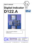
PW336i Hardware User Manual PONOVO POWER CO., LTD 2F, 4Cell, Tower C, In.Do Mansion No.48A Zhichun Road, Haidian District Beijing, China (Post Code 100098) TEL. +86 (10) 82755151 ext. 8887 Office FAX +86 (10) 82755257 E-Mail [email protected] Website www.ponovo.com.cn PW336i HARDWARE USER MANUAL VERSION: DATE : PW336i-AE-3.03 21/09/2011 This manual is the publisher of PONOVO POWER CO., LTD. To make any kind of copy of this manual please contact PONOVO POWER CO., LTD in advance. This manual represents the technical status for the moment of publishing. The product information, description and specifications mentioned in the manual do not have any contact binding force and PONOVO POWER CO., LTD remains the right to make modifications to the technical specifications and configurations without prior notice. PONOVO POWER does not take responsibility to the possible error/mistakes in this manual. 1 PW336i Hardware User Manual Contents 1. 2. 3. 4. Preface ……………………… Safety precaution …………. Designed applications …… Operation preparation …… 3 4 5 6 4.1 Preparation …………………. 4.2 Connecting PC …………….. 6 6 5. General description ……… 5.1 Block Diagram ……………… 5.2 DSP Card …………………… 5.3 Front Panel …………………. 5.4 Ethernet Port ………………… 5.5 Pause Button ………………… 5.6 LED Indication ………………. 5.7 Rear Panel…………………….. 5.8 GPS Interface ………………… 5.9 Multi-kits Synchronization Interface ………………………. 5.10 IP Reset……………………….. …………………………………….... 22 9. 9.1 Analog Recording Unit AR-10/AR-7D ……………………….. …26 9.2 PGPS02-GPS-based Synchronization device …….………………………………27 9.3 PIRIG-B Based Synchronization device……………………….. ……………27 9.4 PSS01 Circuit Breaker Simulator... 28 9.5 PACB108 scanning head………. .28 9.6 Synchronization Control Cable… 28 9.7 Standard Accessories...………… 29 9.7.1 Soft Bag for Test Lead…….. 29 9.7.2 Transportation Case……….. 34 7 7 7 8 8 9 9 11 12 10. Specifications ………………….. 36 11. Appendix………………………… 39 13 14 6. Hardware Configuration …… 15 6.1 Current Generators …………. 15 6.2 Current Output Configuration in 3 Current Mode ……………. 15 6.3 Current in Series Connection in 3 Current Mode ………………… 17 6.4 Voltage Generators ………….. 18 6.5 Connect Two Voltage Generators in Series..………. 18 7. Binary Inputs and Outputs.. PW336i-Related Products and Accessories………………………25 19 7.1 General Description …………. 19 7.2 Binary Input…………. …………. .19 7.3 Polarity of Binary Inputs …….. 20 7.4 Binary configuration…….. …….. 20 7.5 Isolation of Binary Inputs …….. 20 7.6 Threshold for Binary Inputs ….. 20 7.7 Binary Outputs …….. ….. ….. … 21 8. Getting ready for PC Controlled operation……………………… 22 8.1 General Description …………… 22 8.2 Set IP Address ………………… .22 8.3 Steps for Setting IP Address in PC 2 PW336i Hardware User Manual 1.Preface This manual gives detailed introduction to PW336i so that user can have the reasonable, effective and safe operation of this test kit. At the test site user should also refer to other safety and test regulations required by his management authorities. This manual mainly consists of the following parts: This test equipment must be operated by professional test people and careful reading of this manual is required before operating this test equipment. Equipment and functions: This part describes the main hardware parts and their functions. The complete test system consists of PW336i test equipment (used for generating analog test signals), PowerTest test software, Computer which has installed PowerTest software, Test Leads/cables, etc. This manual gives only the description to the hardware part. Please refer to PowerTest software user manual or PowerTest online help for details of the software. Panel description This part describes the interfaces on the panels and their applications Technical specifications This part describes the technical specifications Optional accessories This part describes the optional accessories which will be used for dedicated applications 3 PW336i Hardware User Manual 2.Safety precaution 1. In case the power outlet for powering up the PW336i does not have protective ground users must connect the ground socket of PW336i to the protective ground at the test site 2. Please turn off the output before connecting/disconnecting the test object 3. The voltage output of over 36V is considered as dangerous and care must be taken 4. It’s not allowed to feed external voltage into the voltage/current output sockets 5. It’s not allowed to feed external current into the current/voltage output sockets 6. Disconnect the external circuit from the relay to avoid any influence to the test 7. Do not block the ventilation outlets 8. Avoid the equipment to be wet by rain 9. Do not switch-on and operate the equipment in the place having explosive gas or water vapor 10. The 500V dangerous voltage can be in the equipment and please don’t remove the cover by yourself 11. Please contact the manufacture for any maintenance 12. The guarantee will become invalid if PW336i is opened by the customer 4 PW336i Hardware User Manual 3.Designed applications PW336i can be used by power plants, substations, and relay manufactures, etc, for the following test applications. 2. 3. 1. 2. Test protective relays Test energy meters 4. With optional AR10 or AR-7D analog recording unit the PW336i can even be used for analog waveform analysis. 5. Product features 1. 6. Output sources 6×15A current sources in two groups 4×150V voltage sources 5 Binary inputs 8 binary inputs for potential free or potential contacts Binary outputs 4 binary outputs for potential free contacts GPS interface Can receive GPS pulse signal from optional PGPS02 Can receive signal from IRIG-B based synchronization device Synchronized control interface Used for synchronizing several PW336i for specialized test purpose AR10/AR-7D analog recording unit (optional) PW336i Hardware User Manual 4.Operation preparation 4.1 Preparation Be sure that the following preparation/system components are ready before operating the test equipment: PW336i test equipment Main supply cable (delivered) LAN control cable (delivered) PC with PowerTest software properly installed Test leads connected to the test object 4.2 Connecting PC 1. 2. 3. 4. 5. Connect the LAN cable between PC and PW336i Connect the power cables for PC and PW336i Connect PW336i ground socket to the protective ground Power on the PC and PW336i Run PowerTest software 6 PW336i Hardware User Manual 5.General description 5.1 Block diagram 5.2 DSP Card High performance DSP (digital signal processor) is used on the DSP card to ensure the accurate and fast signal generation. To get the satisfied accuracy and resolution the 32 bit D/A data converting technology is applied. 7 PW336i Hardware User Manual 5.3 Front panel 1. 2. 3. 4. 5. Current Output 1 and 2 (A-C/a-c) Voltage output A,B,C,Z Binary input A-D LED Indication Earth socket 6. 7. 8. Pause Button Communication Interface of Computer (Ethernet) Auxiliary DC Output 5.4 Ethernet port The Ethernet port is used to connect to external PC via Ethernet control cable. Please refer to “Getting ready for connecting to PC” for details 8 PW336i Hardware User Manual 5.5 Pause Button The Pause button on the front panel is designed to cut the current/voltage outputs either for test purpose or under emergency case. Push ‘Pause’ button Release ‘Pause’ button ‘Manual’ control mode cut the current/voltage current/voltage output will be recovered from the point where we push the Pause button ‘Auto’ control mode cut the current/voltage, PC software will continue to run current/voltage output will be recovered from the software execution point at the moment we release the Pause button 5.6 LED Indication The LED indication on the front panel gives information about the hardware working conditions In normal working condition the status of LEDs will have the following indication in ‘Power on’ and ‘Testing process’ conditions 9 PW336i Hardware User Manual Power lamp Online lamp PAUSE lamp Overheat lamp Overload V lamp IA IB IC Ia Ib Ic Power on All current/voltage channels condition are having outputs Lighted Lighted Not lighted Lighted and flashing Not lighted (push to Not lighted(push to light) light) Not lighted Not lighted Not lighted Not lighted Not lighted Not lighted Not lighted Not lighted Not lighted Not lighted Not lighted Not lighted Not lighted Not lighted Not lighted Not lighted 10 PW336i Hardware User Manual 5.7 Rear Panel 1. 2. 3. 4. 5. 6. 7. Binary Input E~H Binary Output 1~4 Multi-kits synchronization interface IP reset 11 GPS interface Connector for mains supply Power switcher PW336i Hardware User Manual 5.8 GPS Interface This interface is used to connect to our optional PGPS02 GPS-based synchronization device or IRIG-B based synchronization device. DB9 Chassis contact, male Signal Power Ready PPS GND GND Contact pin 1 2 3 5 9 ---------------------------------------------Note: PPS means Pulse Per Second ---------------------------------------------One popular application of GPS-synchronized control is for end-to-end test for line protection relay Please refer to PGPS02 User Manual or 9.2 PGPS02-GPS-based Synchronization Device for details 12 PW336i Hardware User Manual 5.9 Multi-kits synchronization interface This interface is used to connect more relay test kits for synchronized control. In synchronized control mode only one PC is required to control all relay test kits. Point-by point synchronization is used to ensure the synchronization accuracy. Router 13 PW336i Hardware User Manual 5.10 IP reset This reset button is used to restore the IP address of PW336I to the default factory setting. Press this button Switching on the power for PW336I After this operation the IP address will be restored to the following settings. IP address: 191.168.1.133 Subnet mask: 255.255.255.0 Note: The IP after reset is only valid for the current operation. If users need to fix the default IP, please set it in “IP set” of PowerTest. 14 PW336i Hardware User Manual 6.Hardware Configuration Power Swing Simulation Transducer 6.1 Current Generators Test modules which requires 6 current mode configuration PW336I has 6 current generators in two groups. They can be configured as either 3 currents mode or 6 current modes. Basic QuickTest(4V or 6V,6I) QuickTest(1V,6I) Time State Sequence(4V,6I) State Sequence(1V,6I) Ramp(6I) QuickTest(4V or 6V,6I) Protection Differential(6I) Advanced Advanced Differential(6I) Test modules which require 3 current mode configurations. Basic Protection QuickTest(4V,3I) QuickTest(VL-L,3I) QuickTest(Sequence) QuickTest(Power) QuickTest(Z,I Const) Time State Sequence(4V,3I) QuickTest(Z,V Const) QuickTest(Z,Zs Const) CB Operate Ramp(3I) Harmonic Non-electricity Check TransPlay(4V,3I) ------------------------------------Notes: There are some changes in the software modules classification; users are suggested to visiting PONOVO website www.ponovo.com.cn for up-to-date information. ------------------------------------- Distance(Z-Phi) Distance(R-X) Differential(3I) VF Trip Relay Time Inversed Current Time Inversed Voltage Directional Under(Over)_Frequency Relay Under(Over)_Voltage Relay U,I,T Relay(AC) U,I,T Relay(DC) Auto-Reclosing Advanced Advanced Differential(3I) Advanced TransPlay(4V,3I) RX Characteristic Sweep Synchronizer Special Energy Meter High Burden Relay 6.2 Current Output Configuration in 3 Current Mode In three 3 current mode the 3 current generators (IA, IB and IC) in first group will be used. 15 PW336i Hardware User Manual In 3 current mode the output range and power for IA, IB and IC will be doubled as shown bellow. Range 3-phase ac (L-N) 1-phase ac (3L-N) 1-phase ac (L-L) 1-phase dc (L-N) 1-phase dc (3L-N) 3 × 0 … 30 A 1 × 0 … 90 A 1 × 0 … 30 A 6 × 0 … ±10A 1 × 0 … ±60 A 3-phase ac (L-N) 1-phase ac (3L-N) 1-phase ac (L-L) 1-phase dc (L-N) 1-phase dc (3L-N) 3 × 240 VA at 30A 1 × 450 VA at 90A 1 × 450 VA at 30A 6 × 100 W at ±10A 1 × 480 W at ±60A Power 16 PW336i Hardware User Manual Example: Settings in QuickTest (4V, 3I) for IA and IB in series connection 6.3 Current in Series Connection in 3 Current Mode In 3 current mode the two current generators can be connected in series to increase the compliance voltage. Example: IA and IB are connected in series IA IB Set Ia and Ib with the same amplitude IC Set Ia and Ib angel as 180 deg Set Ia, Ib as the quantity to change IN 17 PW336i Hardware User Manual 6.4 Voltage Generators VA PW336I has 4 voltage generators. VB VC VZ VN ---------------------------------------------Note: The maximum voltage output will become 300Vac in this case ---------------------------------------------- 6.5 Connect two voltage generators in series We can connect two voltage generators in series to get higher voltage output range. Example: VA and VB are connected in series 18 PW336i Hardware User Manual 7.Binary Inputs and Outputs 7.2 Binary Input 7.1 General Description The device has 8 binary inputs. Electricity is isolated in A-H. Space contact or active contact (15V-250V) can be set by software. The threshold impedance for space contact is shown below. The threshold impedance for active contact can be set by software in 10V-250V. PW336I has 8 binary inputs in two groups. The first group of 4 binary inputs (A, B, C, D) are on the front panel. The second group of 4 binary inputs (E, F, G, H) are on the rear panel. When connecting active contact, the polarity should be correct, red to positive, black to negative, otherwise, false tripping will occur. The polarity for A-H shows below figure. 19 PW336i Hardware User Manual 7.3 Polarity of Binary Inputs 7.5 Isolation of the binary inputs The polarity reference of the binary inputs are shown bellow. All 8 binary inputs are gavanically isolated from each other. 7.4 Binary configuration The software interface for binary configuration (A-H) shows below. 7.6 Threshold for the binary inputs The threshold of 8 binary inputs can be independently set from the range of 0-250 Vdc. ---------------------------------------------Notes:Any end of binary input is prohibited from connecting with ground. ---------------------------------------------- 20 PW336i Hardware User Manual 7.7 Binary outputs PW336I has 4 binary outputs. The binary outputs 1-4 are placed on the rear panel. These 4 binary outputs are potential free relay contact output. 21 PW336i Hardware User Manual 8.Getting Ready for PC Controlled Operation 8.3 Steps for Setting IP Address in PC 8.1 General Description The PW336I is to be controlled by the external PC via the Ethernet control cable. After the PowerTest is installed we need to set the IP address for the computer. The IP address must be set as 192.168.1.* The first three section can not be changed and the last section can be the number among 2~254 (except 133). Steps for setting IP address for computer. PowerTest test software must be properly installed on the PC to control PW336I. The installation description of PowerTest test system can be found in PowerTest user manual. Step 1: Left click ‘Start/Control panel/Network connection’ (or right click the icon of “Network Neighbour” and left click the ‘Properties’ of drop menu) on the desktop of win2000 or winXP To connect the computer to PW336I a 10M/100M Ethernet Network Interface Card (NIC) must be installed in the PC. The computer without network card could use a UBS NIC. The drive program of NIC also should be installed. The computer with mounted NIC should be able to log on Internet properly. 8.2 Set IP Address The IP address of PW336I is internally fixed as 192.168.1.133 when dispatched from the factory. 22 PW336i Hardware User Manual Step 2: Right click ‘Local connection’ icon Step 4: Click the ‘Properties’ button Step 3: Left click the ‘Properties’ ---------------------------------------------Note: the last section of IP address can be any number between 2-254 (except 133) ---------------------------------------------Step 5: Make the settings Select ‘Use the following IP address Set ‘IP address’ as 192.168.1.2 Set ‘Subnet mask’ as 255.255.255.0 Press ‘OK’ button to confirm the setting Step 6: Make the settings In ‘Local connection’ window make the following selection Then click the ‘OK’ button to complete the IP setting. 23 PW336i Hardware User Manual Step 7: Check if IP is set properly If IP address is properly set we will see on the right bottom corner the following display If we see the following display on the right bottom corner then we need to make the check as mentioned bellow Check if control cable is connected Check if PW336I is powered up Check if IP address is set properly 24 PW336i Hardware User Manual 9.PW336i-Related Products and Accessories This chapter describes the optional equipments and accessories for the PW336i test set. Please visit the PONOVO Web site www.ponovo.com.cn for up-to-date information. Optional accessories Standard accessories Item AR-10 analog recording unit AR-7 analog recording unit PGPS02 GPS based synchronization device IRIG-B based synchronization device PSS01 circuit breaker simulator PACB108 scanning head Synchronization control cable Item Color coded current cables Color coded voltage cables Signal cables Flexible terminal adapter Flexible jumpers Crocodile clips U clamps 1# U clamps 2# Pin clamps Power cord Earthing lead PC control cable (LAN) Transportation case Part No. SAR0101 SAR0201 SAG0101 SAG0102 SAB0101 SAS0101 SAW0015 25 Part No. SAW0201/0203 SAW0202 SAW0204/0205 SAW0206 SAW0207 SAW0208 SAW0209 SAW0210 SAW0211 SAW0009 SAW0018 SAW0012 SAC0105 PW336i Hardware User Manual 9.1 Analog Recording Unit (AR-10/AR-7D) SAR0101 AR-10 SAR0201 AR-7D The optional AR-10 or AR-7D analogue signal recording unit can be installed on the top cover of the test equipment. Main specifications of AR-10/AR-7D This facility can be used to monitor the current/voltage outputs and binary input/output status during the relay test process enabling the fast trouble shooting of wiring and test circuitry. We can also use this provision to analyze the external signals, such as phase angle, power, harmonic, etc. 26 Item No. of analog recording channel AR-10 AR-7D 10 7 Voltage input range 0-300Vac 0-300Vac/dc Current input range 0-30Aac 0-30Aac/dc PW336i Hardware User Manual 9.2 PGPS02-GPS-based Synchronization Device 9.3 PIRIG-B Based Synchronization Device It provides GPS synchronization signal in PPS (pulse per second) or PPM (pulse per minute) for synchronized test. Trigger time can be set locally. It converts external IRIG-B signal into trigger pulse to synchronize several of our relay test equipment for synchronized test application. SAG0102 PIRIG-B SAG0101 PGPS02 Via the PIRIG-B interface box users can connect devices to the PW336i test set that either transmit or receive the IRIG-B time reference signal (DC level shift protocol B00x). That way, two or more PONOVO test sets are synchronized. You can synchronize two or more PONOVO test sets by connecting a PGPS synchronization unit to each of the test sets’ inputs. For detailed information about the PGPS, please refer to the PGPS User Manual, the product catalog, or the PONOVO Web site www.ponovo.com.cn For detailed information about the PIRIG-B, please refer to the PIRIG-B User Manual Table 8-2 Pulse signal level TTL or RS-232 Timing error between two RT GPS TYP.<100ns MAX.<500ns Pulse width 100ms Weight 640g Dimension W x H x D 95x45x160mm 27 PW336i Hardware User Manual 9.4 PSS01 Circuit Breaker Simulator 9.5 PACB108 Scanning Head The passive optical scanning head PACB108 detects the status of an LED, that is either an optical pulse output from an energy meter or the binary status of a protective relay or other similar optical source. It can simulate circuit breaker behaviors in three pole or 1 pole tripping of 6-500KV voltage grade, being available for power system, etc. It provides 12 circuit breaker auxiliary contacts for complex test applications. SAS0101 PACB108 Output pulse: 5V or 24V Sampling distance: 10-30 mm Maximum sampling pulse: 100 pulses/second SAB0101 PSS01 This is one of the application examples: 9.6 Synchronization Control Cable Synchronization control cable is used to connect more relay test kits for synchronized control. SAW0015 Synchronization control cable 28 PW336i Hardware User Manual 9.7 Standard Accessories 9.7.1 Soft Bag for Test Leads The PW336i Wiring Accessory Package contains the following articles: 1. Colour coded current cables SAW0201/ 0203 colour coded current cable Amount: 1xred, 1xblack, 1xyellow, 1xblue 2xred, 2xblack, 2xyellow, 2xblue The current cables to connect the PW336i output to other safety sockets of, generally the current parts, voltage and signal tripping. 29 PW336i Hardware User Manual 2. Color coded voltage cables SAW0201 Colour coded voltage cable Amount: Amount: 1x red, 1x yellow, 1x green, 1x blue, 1x black The voltage cables to connect the PW336i output to other safety sockets of, generally the voltage parts, current and signal tripping. 3. Signal Cable SAW0204/0205 Signal cables Amount: 2xred, 2x black 2xred, 2xblack It connects the PW336i with other different sockets, generally with signal tripping and current/voltage testing. 30 PW336i Hardware User Manual 4. Flexible Terminal Adapter SAW0206 Flexible terminal adapter Amount: 10xred, 10xblack Flexible terminal adapter connect to screw-clip terminals. ----------------------------------------------------------------------------Notes: One end of the adapters have no insulator, users should make sure there is no output during connecting the adapters. Users insert the non-safety into the terminals and screw it firmly, then connect the test lead with the other end. ------------------------------------------------------------------------------ 31 PW336i Hardware User Manual 5. Jumper Cable Jumper cable Ponovo kit Device with safety jack SAW0207 Flexible jumpers Amount: 4xblack Flexible jumper connects current outputs in parallel. 6. Crocodile Clips SAW0208 Crocodile clips Amount: 2xred, 2xblack, 2xyellow, 2xblue Crocodile clips for secondary side to connect to pins or screw types. 32 PW336i Hardware User Manual 7. U Clamps SAW0209 U clamps 1# Amount: 10xred, 10xblack SAW0210 U clamps 2# 5xred, 5xblack It is used to connect test leads with screw type terminals. -----------------------------------------------------------------------------------------Notes: One end of the adapters have no insulator, users should make sure there is no output during connecting the adapters. Users insert the non-safety into the terminals and screw it firmly, then connect the test lead with the other end. ----------------------------------------------------------------------------------------- 33 PW336i Hardware User Manual 8. Pin clamps SAW0211 Pin clamps Amount: 4xred, 4xblack It is used to connect test leads with screw type terminals. 9. Power Cord SAW0009 Power code Amount: 1 piece Power cord connects the PW336i with power supply socket. PONOVO will provide relevant plug socket according to different countries. For the plug socket information, please check the Chapter 11. Appendix. 34 PW336i Hardware User Manual 10. Earthing Lead SAW0018 Earthing lead Specification: 2.5mm²×4m Amount: 1 piece Earthing lead connects the PW336i with ground to ensure kit safety. ----------------------------------------------------------------------------Notes: In order to avoid static induction, users should connect the PW336i with ground reliably before testing. ----------------------------------------------------------------------------11. PC control cable (LAN) SAW0012 PC control cable (LAN) Amount: 1 piece The LAN cable connects the PW336i with PC for communications. 35 PW336i Hardware User Manual 9.7.2 Transportation Case The large-size case with wheels is designed for heavy transport stress with folding hand it is made of fireproof materials and smooth rolling rubber tires. SAC0105 Transportation case Dimension: 465x250x525mm (WxHxD) Weight: 10Kg. 36 PW336i Hardware User Manual 10.Specifications Voltage Generators Binary Input & Output Setting range 4-phase ac (L-N) 4 × 0-150V 1-phase ac (L-LL) 1 × 0-300V dc (L-N) 4 × 0-±150V Power 4-phase ac (L-N) 4 × 60VA at 150V, 1-phase ac (L-L) 1x 120VA at 300V dc (L-N) 4 × 40W at ±150V General Accuracy < 0.08% rd + 0.02% rg guar. < 0.04% rd. +0.01% rg.typ., at 0-150v Ranges 150V Resolution 5mV for 150Vac Distortion < 0.05% typ. (0.1% guar.) Binary inputs Number Input characteristic 8 0-400Vdc threshold or potential free Time resolution 50µs Max. measuring time infinite Debounce/Deglitch time 0-25ms Counting function <3kHz at pulse width >150us Galvanic isolation 8 galvanically isolation Binary output, relay Number Type Break capacity ac Current Generators Setting range 6-phase ac (L-N) 3-phase ac (L-N) 1-phase ac (3L-N) dc (L-N) dc (3L-N) Power 6-phase ac (L-N) 3-phase ac (L-N) 1-phase ac (3L-N) 1-phase ac (L-L) dc (L-N) dc (3L-N) General Accuracy Ranges Resolution Distortion Break capacity dc 6 × 0-15A 3 × 0-30A 1 × 0-90A 6 × 0-±10A 1 × 0-±60A DC voltage measuring inputs Measuring range Accuracy Input impedance 6 × 150VA at 15A 3 × 240VA at 30A 1 × 450VA at 90A 1 × 450VA at 30A 6 × 100W at ±10A 1 × 480W at ±60A Measuring range Accuracy Input impedance 0-±20mA <0.02% rg. typ.; 0.05% rg, guar 50Ω AC measurement & monitoring (optional) Voltage measurement Channel number Measuring range Phase Current measurement Channel number Measuring range Phase Power measurement Active/reactive power Monitoring Channel number Mode Generator, general Phase angle resolution 0-±10V 0.02% rg. typ; 0.05% rg, guar 100kΩ DC current measuring inputs < 0.15% rd + 0.05% rg guar. < 0.05% rd + 0.02% rg typ.at 0-15A 15A or 30A 1.0mA < 0.05% typ. (0.1% guar.) Frequency range Sine signal Frequency accuracy Frequency resolution Phase angle range Phase angel accuracy 4 Potential free relay contact, controlled via software Vmax:300Vac / Imax:8A /Pmax:2000VA) Vmax:300Vdc / Imax:8A /Pmax:150W DC, 1-2000Hz ±1ppm 0.001Hz -360° -+360° (Lead) 0.05° typ (0.1° guar) at 50/60Hz ±0.001° Auxiliary DC supply 4 0-300V (error < 0.5% rg. typ.) 0-360° (error < 0.5°) 6 0-30A (error < 0.5% rg. typ.) 0-360° (error < 0.5°) error < 1% rg. typ. 10 monitoring the output voltage/current waveform during the test process Power supply Voltage range 0-300V Power 88W at 110V, 176W at 220V, 120 W at 300V Accuracy <0.1% rg typ. (<0.5% rg. guar.) Nominal input voltage 110-240Vac Permissible input voltage 90-260Vac Nominal frequency 50/60Hz Permissible frequency 45-65Hz 37 PW336i Hardware User Manual Environmental condition Operating temperature Storage temperature Relative humidity EMC (Emission) EMC (immunity) Safety 0-+50°C -25-+70°C 5-95%, non-condensing IEC-61000-3-2/3 IEC-61000-4-2/3/4/5/6/11 IEC 61010-1 Others PC-Connection Ethernet, 10M/100Mbps Amplifier interface Circular connector Current booster interface Circular connector Synchronization interface Coaxial cable connector GPS control interface RS232 Ground socket (earth) 4 mm banana socket Weight 20 kg Dimensions 360 × 157 × 367 mm Analog recording unit (optional) Channel number Voltage input range Current input range Amplitude accuracy Bandwidth Sampling frequency Voltage input impedance Transient input buffer Transient trigger Measurement function Input overload indication Input protection Galvanic isolation AR-10 AR-7D 10 0-300V ac 0-30A ac 0-300Vac/dc 0-30Aac/dc < 0.5% DC-1.0kHz 3.5kHz 300kΩ 15s for all 10 inputs channels simultaneously at 3.0kHz threshold voltage or current, manual I (AC), V (AC), phase, frequency, power, energy, harmonics, transient recording, event recording Yes Yes Independent isolation for all 10 inputs IEC61850 compliant relay testing (optional) IEC61850 GOOSE Simulation Subscription Performance VLAN support Mapping of binary outputs to data attributes in published GOOSE message Mapping of data attributes from subscribed GOOSE messages to binary inputs Type 1A; Class P2/3 (IEC61850-5) selectable priority VLAN-ID 38 PW336i Hardware User Manual 11.Appendix In order to assure PONOVO sockets are used smoothly in foreign countries, PONOVO provides the plug sockets to our customers in different countries. The followings are the sockets used in different countries. 1. Plug Type B Type B adapter is mainly used in America, Canada and Taiwan etc. 39 PW336i Hardware User Manual 2. Plug Type I Adapter The UK type plug is mainly used in United Kingdom, India, Pakistan, Thailand, Malaysia, Singapore, New Zealand and Hong Kong etc. 3. Plug Type L Adapter Type L Adapter is mainly used in South Africa and British Standard 15A. 40 PW336i Hardware User Manual 4. Plug Type N Adapter This adapter is mainly used in Italy. 5. Type G Adapter Type G Adapter is mainly used in German, Finland, France, Norway, Sweden, Poland, South Korean, Austria, Spain, Hungary, Czech, Ukraine, Turkey, Brazil and Russia etc. 41