1
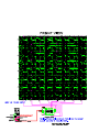
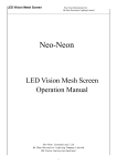
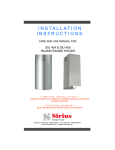
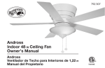
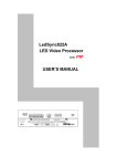
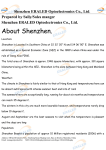
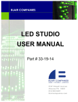
USER MANUAL
LED Pixel
Mesh
Keep this manual for future needs!
© Copyright
Reproduction prohibited!
Warning.................................................................................…...……………..…………………………….………..…. 2
Safety-instructions………………………………………………………………………………………………………… 2
Operating Determinations.…………………………………………………………………………………………….. 3
Description...............................................................................…...………………………………………….………..… 4
Features and Overview ………………………………...….……………….………….……….……….……………… 4
Overall Requirements……….…………………….……………………….……………………….……………………..… 5
Computer System Requirements……….……………………….……………………….………………………….…….. 5
Set Up and Operation.....................................................................……..……………………………………………… 5
LED Pixel Mesh Limitations ……………………………………………………………………….……...……….…….. 5
Included with the Software Bundle………………………………………………………………………..………….. 6
Communication Wire Facture…………………………………………………………………………………………. 7
Making an additional Net-cable……………………………………………………………………………………… 7
How to connect the Pixel Mesh……………………………………………………………………………………… .. 8
IEC and Data Output Connections…………………………………………………………………………………… 9
Screen Control System Instruction…………………………………………………………………………………….. 10
PC Host Computer……………………………………………………………………………………………………….. 10
System Connection Mode……………………………………………………………………………………………… 11
System Connection Chart………………………………………………………………………………………………. 11
Mounting System to LED Screen Connection………………………………………………………………………. 12
Sender card……………………………………………………………………………………………………………….. 14
Backside View…………………………………………………………………………………………………………….. 15
Sender card Installation……………………………………………………………………………..………………….. 16
LED Vision Studio MX Control System Installation…………………………………………………………………… 17
Display Card Settings……………………………………………………………………………………………………. 18
ATI Display Card Settings……………………………………………………………………………………………….. 18
GEFORCE Display Card Settings………………………………………………………………………………………. 20
Receiver Card Configuration………………………………………………………………………………………….. 22
Maintenance...................................................................................………..………….…….……………………….… 25
Troubleshooting............................................................................………………….………………….………………... 25
Product Specifications.................................................................……………….…….……………………………….. 26
1
WARNING
FOR YOUR OWN SAFETY, PLEASE READ THIS USER MANUAL CAREFULLY
BEFORE YOUR INITIAL START-UP!
SAFETY INSTRUCTIONS
Every person involved with the installation, operation and maintenance of this dev ice has to:
be qualified
follow the instructions of this manual
CAUTION! Be careful with your operations.
With a dangerous voltage you can suffer
a dangerous electric shock when touching the wires!
Before your initial start-up, please make sure that there is no damage caused by transportation. Should
there be any, consult your dealer and do not use the device.
To maintain perfect condition and to ensure a safe operation, it is absolutely necessary for the user to
follow the safety instructions and warning notes written in this manual.
Please consider that damages caused by manual modifications to the device are not subject to
warranty.
This device contains no user-serviceable parts. Refer servicing to qualified technicians only.
IMPORTANT:
The manufacturer will not accept liability for any resulting damages caused by the nonobservance of this manual or any unauthorized modification to the device.
Never let the power-cord come into contact with other cables! Handle the power-cord and all
connections with the mains with particular caution!
Never remove warning or informative labels from the unit.
Do not open the device and do not modify the device.
Do not connect this device to a dimmerpack.
Do not shake the device. Avoid brute force when installing or operating the device.
Do not switch the device on and off in short intervals.
Never use the device during thunderstorms, unplug the device immediately.
Only use device indoor, avoid contact with water or other liquids.
Avoid flames and do not put close to flammable liquids or gases.
Only operate the device after having familiarized with its functions.
Always disconnect power from the mains, when device is not used or before cleaning! Only
handle the power-cord by the plug. Never pull out the plug by tugging the power-cord.
Make sure that the device is not exposed to extreme heat, moisture or dust.
Make sure that the available voltage is not higher than stated on the rear panel.
Make sure that the power-cord is never crimped or damaged. Check the device and the powercord from time to time.
If the external cable is damaged, it has to be replaced by a qualified technician.
If device is dropped or struck, disconnect mains power supply immediately. Have a qualified
engineer inspect for safety before operating.
If the device has been exposed to drastic temperature fluctuation (e.g. after transportation), do
not switch it on immediately. The arising condensation water might damage your device. Leave
the device switched off until it has reached room temperature.
If your dev ice fail s to work properl y, discontinue use immediatel y. Pack the unit securel y
(preferabl y in the orig inal packing m aterial ), and return it to your dealer for serv ice.
2
The user is responsible for correct positioning and operating of the LED Pixel Mesh. The
manufacturer will not accept liability for damages caused by the misuse or incorrect installation
of this device.
This device falls under protection class I. Therefore it is essential to connect the yellow/green
conductor to earth.
Repairs, servicing and electric connection must be carried out by a qualified technician.
For repl acement use fuses of same type and rat ing onl y.
OPERATING DETERMINATIONS
This device is not designed for permanent operation. Consistent operation breaks will ensure that the
device will serve you for a long tim e without defects.
The maximum ambient temperature t a = 45°C must never be exceeded.
The relative humidity must not exceed 50 % with an ambient temperature of 45° C.
If this device is operated in any other way, than the one described in this manual, the product may suffer
damages and the warranty becomes void.
Any other operation may lead to dangers like short-circuit, burns, electric shock, lamp explosion, crash
etc.
You endanger your own safety and the safety of others!
Improper installation can cause serious damage to people and property !
Connection with the mains
Connect the device to the mains with the power-plug.
Always pay attention, that the right color cable is connected to the right place.
International
EU Cable
UK Cable
US Cable
Pin
L
BROWN
RED
YELLOW/COPPER
FASE
N
BLUE
BLACK
SILVER
NUL
YELLOW/GREEN
GREEN
GREEN
EARTH
Make sure that the device is always connected properly to the earth!
Improper installation can cause serious damage to people and property !
3
Description of the device
Features
The LED Pixel Mesh is a fabul ous LED Lighteffect
• Average Lifespan: 50,000~100,000hrs
• Mounting system has rigging points and flexible configurations
• Rated Power: 75W
• Cooling: Direct air convection
• LED/Pixel: 2xRED/1XGREEN/1XBLUE
• Module size: 640mm×640mm×65mm
• Pixel/Unit:16*16
• Pixel Pitch:40mm
• Pixel Density(dot/ m2):625
• Pixel composition:2R1G1B 4Φ5 oval LED
• Brightness(cd/ m2):1300
• Optimal viewing distance(m):60
• Module peak value power(≤W):75
• Module average power(≤W):40
• Module weight(kg):10
• Scanning mode:Static scan
• Viewing angle:120°(60°horizontally and vertically)
• Driven voltage(V):4.5~5.5
• Gray scale:256 levels respectively
• Frame change speed:≥60(frame/second)
• Control mode:In step with the computer monitor
• Blind spot rate:≤0.0002
• Operating voltage:AC220V±15% 47~64HZ
• Control distance(m):<130
• Temperature environment:-10℃~50℃
• Humidity environment:10%~90%RH
• Indoor use only
Control
• Software: LEDstudio 8
• System: Windows XP with video card (NOT included)
• Applications: Fixed installations, small or large, interior / advertising /stage
• Works with other manufacturer’s software: Arkaos or Sweetlight Timeline
Overview
Fig. 1
Pixel Mesh (101150)
Pixel Mesh Controller (101151)
4
Overall Requirements
• Windows XP computer with an available PCI slot
• Graphics card with 2x DVI or 1x VGA + 1x DVI
• LED Pixel Mesh Controll er; 1 controll er for every 16 panel s wide and 8 panel s high
Computer System Requirements
Minimum
Operating system: Windows XP SP2 (Service Pack 2)
Processor: Pentium 200 MHz with at least one free PCI slot
Harddisk: 20 GB 5400 RPM
Memory: 128 MB
Graphic Card: Graphics Card with dual display Mode and DVI output
Note: Only tested with ATI Graphic Card
Recommended
Operating system: Windows XP SP2 (Service Pack 2)
Processor: Pentium 1 GHz or better with at least one free PCI slot
Harddisk: 40 GB 7200 RPM or more
Memory: 512 MB or higher
Graphic Card: Graphics Card with dual display Mode and DVI output
Set Up and Operation
Before plugging the unit in, always make sure that the power supply matches the product specification
voltage. Do not attempt to operate a 120V specification product on 230V power, or vice versa.
Always disconnect from electric mains power supply before cleaning or servicing.
Damages caused by non-observance are not subject to warranty.
The LED Pixel Mesh can only be used indoors. The LED Pixel Mesh can be viewed during night-time as well
as day-time. Due to the clever mounting system it is easy to setup. The LED Pixel Mesh excellent design
allows you to vary the setup in many shapes and sizes.
LED Pixel Mesh Limitations
Note: 1 LED Pixel Mesh Controll er for every 16 panel s wide and 8 panel s high
Horizontal Panels (Left/Right)
Minimum 1 Panel
Maximum with 8 panels (1 Controller)
16 columns of LED clusters or 16 horizontal pixels/lines
128 columns of LED clusters or 128 horizontal pixels/lines
Vertical Panels (UP/Down)
Minimum 1 Panel
Maximum with 16 panels (1 Controller)
16 rows of LED clusters or 16 vertical pixels/lines
256 rows of LED clusters or 256 vertical pixels/lines
Resolution
Minimum 1 Panel
Maximum With (1 Controller)
16 X 16 Pixels
256 X 128 Pixels
1 Panel is 16 by 16 pixels on your PC screen.
So 8 x 6 panels (5,12 x 3,84 meters) = a resolution of 128 x 96 pixels in Windows XP.
5
Included with the Software Bundle
User manual
PC Sender Card
DVI cable (DVI to DVI)
Fig. 2
RS232 to RJ-11 cable
CD with LED Studio 8
6
Communication Wire Facture
Cable from Computer to Scan Board 20m
INPUT
OUTPUT
1
White/Orange
White/Orange
2
Orange
Orange
3
White/Green
White/Green
4
Blue
Blue
5
White/Blue
White/Blue
6
Green
Green
7
White/Brown
White/Brown
8
Brown
Brown
Cable from Scan Board to Mesh Panel 3,5m
1
White/Orange
Brown
INPUT
OUTPUT
2
Orange
White/Brown
3
White/Green
Green
4
Blue
White/Blue
5
White/Blue
Blue
6
Green
White/Green
7
White/Brown
Orange
8
Brown
White/Orange
Cable between Mesh Panels
INPUT
OUTPUT
1
White/Orange
Blue
2
Orange
White/Brown
3
White/Green
White/Blue
4
Blue
White/Orange
C-Side
5
White/Blue
White/Green
1
A-Side
B-Side
6
Green
Brown
7
White/Brown
Orange
8
Brown
Green
8
B-Side
Fig. 3
D-Side
Making an additional cable from the computer to the Scan Board
A Standard NET CABLE cannot be used to replace the NET CABLE required to transmit the information for
the LED Pixel Mesh.
Please follow the following instructions in order to create extra NET CABLE.
Take a standard net cable (Cat5/ 5E /6) and connect it to the RJ-45 connector just like displayed on the
picture. The wires should now be colored as following:
1- white & orange
2- orange
3- white & green
4- blue
5- white & blue
6- green
7- white & brown
8- brown
RJ-45 Connector
Insert each wire into an RJ-45 connector with the white & orange wire connected to PIN 1, the orange
wire connected to the second PIN, etc.
Both ends of the NET WIRE are connected in this way.
7
How to connect the Pixel Mesh
Fig. 4
Note:
Always make sure that all bolts are securely fastened.
Do not use on systems larger than 5,12 meters in height ( 8 panels)
8
IEC and Data Output Connections
AC Output
AC Input
16 15 12 11 8 7
4
3
2
Data Input
Data Output
6
9
5
10
14 13
1
Fig. 5
9
Screen Control System Instruction
Sender card:
• Make sure the PC is switched off. Take anti-static precautions, otherwise the entire PC can become
damaged.
• Install the sender card on the PCI slot of the PC;
• Connect the DVI Port of the transmission card and DVI Display Port by DVI Cable;
• Connect the PC host computer serial port and the transmission card RS232 serial port by serial wire.
• Start your PC.
• The green indicator light on the stage of twinkle status when the modules work normally.
Fig. 6
PC Host Computer
• PC should contain a Graphic Card with a double output: • VGA + DVI output
• DVI + DVI output
• We usually recommend to use “GEFORCE Display Card” or “ATI Display Card”,the operation system is
WINDOWS XP.
10
System Connection Mode:
• DVI Cable: connect the DVI Port between the PC and sender card (Fig. 7)
• RS232 Serial Cable: connect the serial port between the PC and the sender card (Fig. 8).
• SUPER CAT ISDN 8-Pin Cable: connect the sender card and receiving card with SUPER CAT ISDN 8Pin Cable in order to achieve data transmission (Fig. 9).
Fig. 7
Fig. 8
Fig. 9
System Connection Chart
• Installation the transmission card on the PCI Slot of the PC, connect the sender card and RS232
serial port by DVI Cable
• Connect the receiving card and PC with SUPER CAT ISDN Cable (1).
• Connect the receiver card and the screen modules with LAN cable the NET CABLE (2).
• Connect the receiver card to the Pixel Mesh Boards (3).
Fig. 10
11
Mounting System to LED Screen Connection
Note:
These bolts only need to be removed when a LED Panel needs to be moved or serviced.
Each screen has to be fixed by its M6 holes on the side of each screen.
There are 8 M6 holes in total.
Front View
Fig. 11
12
13
Sender card
Install the sender card in an available PCI slot in your computer. The sender card is the interface between
your PC, LED Studio and the LED Pixel Mesh. You must use the DVI cable provided to connect from the
computers DVI output to the DVI port on the sender card.
Data Out 1 & Data Out 2 connectors
The 2 network output ports transmit 128 rows or horizontal lines. Output 1 transmits rows/lines 1 throug 128.
output 2 transmits rows/lines 129 through 256.
Aux Port
This is a standard 6-pin telephone connector. A cable is provided that connects from the 9-pin DIN R-232
port to the AUX port on the sender card. This port allows control of the R variable, gray scale, DV Wall
matrix active area, and matrix lock and matrix range.
DC External Power Input
This input takes the 5V power supply provided. It is only used if the sender card will be operated eternally
of the computer.
14
Backside view
Fig. 12
15
Sender card installation
1) Turn off your computer and disconnect from the powersource. Always take these precautions before
opening the case and adding/removing components.
2) Insert the sender card into an available PCI slot in your computer.
3) Connect the DVI output from your computer’s display card to the DVI input on the sender card,
Using the DVI signal cable provided.
4) Connect your computer’s serial RS232 (also known as COM port) connector to the 6-pin telephone
connector of the sender card, using the RS232 signal cable provided.
5) Connect the RJ45 OUT 1 connector to the controller’s Net IN connector with the provided net cable to
display rows 1 through 128.
6) When you want to display 256 row lines, connect the OUT 2 to a second controller.
7) Make sure that all connections are correctly connected, before applying power to the entire system.
8) In order to test the system successfully, it will be necessary to address the controllers correctly.
9) Once the controllers are assigned, turn on the computer and test the system.
Fig. 13
Warning
When your PC starts up and your screen stays black after connecting the sender card, turn off your
computer immediately and disconnect the DVI cable from the sender card. Reboot your PC and when
Windows has loaded, reconnect the DVI cable.
16
LED Vision Studio MX Control System Installation
• Put the LED Vision Studio MX CD in the PC and then enter the installation setup.
If not, please double click the CD, choose LED Vision Studio MX Installation to start the installation.
The Display shows LED Vision Studio MX (see Figure below).
• The following icon will appear on the desktop after finshing the entire installation:
• Double click the Chart Icon to start the following screen:
• For detailed information of the “ LED Vision Studio MX” please refer to user's manual.
17
Display Card Settings
ATI Display Card Settings
1) Press the right MOUSE button, when standing on a blank desktop.
Go to Properties, and set the screen resolution to 1024 x 768 pixels:
2) Press Advanced to set the refresh rate of the monitor to 60HZ:
18
3) Press the Display options and choose FPD, button will turn green:
4) Press cover options and choose copy mode options in the new popup screen to setup all the same:
19
GEFORCE Display Card Settings
1) Press the right MOUSE button, when standing on a blank desktop.
Go to Properties, and set the screen resolution to 1024 x 768 pixels:
2) Press Advanced to set the refresh rate of the monitor to 60HZ:
20
3) Press the GeForce 7100 GS options, setting the nView. Choose the nView Display Settings menu, and
press Clone:
Choose Application and then Confirm. Now exit your Properties setup.
21
Receiver Card Configuration
Configure the Receiv er Card after you have finished the LED Studio setup by installing main control card,
receiving card, screen and connecting signal wire and power supply wire.
Generally speaking, users do not need to configure the receiving card because the supplier has already
set it before deliving the goods.
The Configuration mode for the Receiv ing Card is, as follows:
1) Press Software Setup on the menu
2) Enter the screen of software setup.
22
3) Then type linsn on the keyboard and press enter.
Note: there is no indication on the screen.
After this a popup appears on the screen, requesting a password.
You should enter the password in the popup. The password is“168”.
Then press OK.
If you have entered the correct password, the following hardware-setup appears on the screen:
Sender Setup
The Sender Setup is very simple, you do not need to do any work, if your display operation remains below
1024×768 mode. Otherwise you should choose the display mode and then press “Save to the Sender”
and all will be ok.
23
Receiver Setup
The setup has already been perfected, so users do not need to do any work on the Receiver Setup.
The configuration file is included with the LED Pixel Mesh: Pixel Mesh.RCG
Users can refer to the following steps if they want to alter the configuration:
Press “Load from files” on the Receiver Setup,
After load files, suggest
config as following
parameter!!
Then press “send to receiver” and “save on receiver” step by step, then input “256” in actual width, and
“128” in actual height, please see above green circle.
The Configuration of Receiv er has already done after all that setup is complete.
24
Maintenance
The operator has to make sure that safety-relating and machine-technical installations are to be
inspected by an expert after every four years in the course of an acceptance test.
The operator has to make sure that safety-relating and machine-technical installations are to be
inspected by a skilled person once a year.
The following points have to be considered during the inspection:
1. All screws used for installing the device or parts of the device have to be tightly connected and must
not be corroded.
2. There may not be any deformations on housings, fixations and installation spots.
3. Mechanically moving parts like axles, eyes and others may not show any traces of wearing.
4. The electric power supply cables must not show any damages or material fatigue.
The LED Pixel Mesh requires alm ost no m aintenance. However, you shoul d keep the unit cl ean.
Otherwise, the fixture’s light-output will be significantly reduced. Disconnect the mains power supply, and
then wipe the cover with a damp cloth. Do not immerse in liquid. Wipe lens clean with glass cleaner and
a soft cloth. Do not use alcohol or solvents. Keep connections clean. Disconnect electric power, and
then wipe the connections with a damp cloth. Make sure connections are thoroughly dry before linking
equipment or supplying electric power.
Troubleshooting
Please check system according to the following steps if the LED Screen can not work normally after
finishing the connection and the power on:
Trouble Description
Whole screen
Blackout
Screen twinkle
Control system out
of control
Trouble Analysis
The power supply does not work
Solution
Power on
LED control software does not turn on.
Transmission line does not connect well
Setting control software
Reconnect transmission
line
Reset the desktop menu
Make sure the voltage
above 4.75V
Cut off the cable line
Display shows black color
Frame module power supply does not connect
well or voltage does not match
Connecting wire between module and
scanning board are above stated length
Data wire above the stated length or some
trouble with cable wire
Connect data wire does not fasten well
Unit board has some trouble
Display card setting does not correct
Set the LED control software locked
Do not increase power supply when increasing
power supply to the module
Ensure the cable wire
quality
Re-plug
Check the module
Reset the display card
Set the control software
unlock
Add power source to
scanning controller
If you are unable to determine the cause of the problem, do not open the LED Pixel Mesh, as this may
dam age the unit and the warranty wil l become void. Pl ease return the dev ice to your dealer.
25