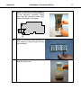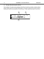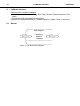
1
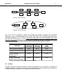
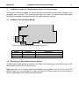
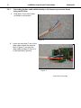
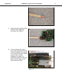
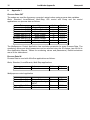
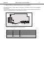
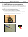
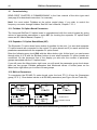
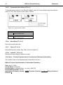
Honeywell
indexa
1(57)
Honeywell
User Manual
NX series
LonWorks & BACnet User Manual
62-0303-01
2
Index
Honeywell
INDEX
1.
General .........................................................................................................................5
2.
LonWorks C4 Option Board Technical Data .............................................................6
2.1 General ...................................................................................................................6
2.2 Physical Media and Wiring......................................................................................6
2.3 Profiles ....................................................................................................................7
2.3.1 Variable Speed Drive Profile.............................................................................8
3.
LonWorks Fieldbus C4 Option Board Layout and Connections .............................9
3.1 LonWorks Opt-C4 Option Board .............................................................................9
3.2 Grounding Of Bus Cable Shield In Opt-C4..............................................................9
3.2.1 Grounding the bus cable shield directly to the frequency converter frame
using the RC-filter .......................................................................................................10
3.3 Bus Termination Resistor......................................................................................12
3.4 Led Indications......................................................................................................12
4.
Installation of Honeywell NX LonWorks C4 Option Board.....................................14
4.1 C4 Option Board Information Sticker.....................................................................16
5.
Commissioning .........................................................................................................17
5.1 Fieldbus C4 Option Board Parameters .................................................................17
5.2 Start-Up Test.........................................................................................................17
6.
LonWorks Interface...................................................................................................18
6.1 General .................................................................................................................18
6.2 Input Network Variables ........................................................................................20
6.3 Output Network Variables .....................................................................................23
6.4 Network Configuration Variables...........................................................................26
6.5 Process Data ........................................................................................................28
7.
Fault Tracking............................................................................................................29
8.
Appendix 1 .................................................................................................................30
9.
General Info ...............................................................................................................32
10. BACnet CJ Option Board Technical data ................................................................33
10.1 System Software versions.....................................................................................34
11. Bacnet Fieldbus CJ Option Board Layout and Connections.................................35
12. Grounding Cable Shield............................................................................................36
12.1 Grounding by clamping the cable to the converter frame (recommended)............36
12.2 Grounding only one point on the net .....................................................................38
12.3 Bus Terminal Resistors .........................................................................................39
12.4 Bus Biasing ...........................................................................................................39
13. Led Indications ..........................................................................................................41
14. Installation of Honeywell NX BACnet CJ Option Board .........................................42
15. Commissioning .........................................................................................................44
15.1 Fieldbus CJ Option Board Parameters..................................................................44
15.2 Expander CJ Option Board Menu (M7) .................................................................44
15.3 BACnet Parameters ..............................................................................................44
15.3.1 Ms/Tp Mac Address (P7.X.1.1).......................................................................45
15.3.2 Baud Rate (P7.X.1.2)......................................................................................45
Honeywell
Index
3
15.3.3 Instance Number (P7.X.1.3) ...........................................................................45
15.3.4 Communication Time-Out...............................................................................45
15.3.5 Communication Status (V7.X.2.1)...................................................................46
15.3.6 Baud Rate (V7.x.2.2) ......................................................................................46
15.3.7 Fault (V7.x.2.3) ..............................................................................................46
15.3.8 Index Nr. (V7.x.2.4)........................................................................................46
15.4 Annex - Protocol Implementation Conformance Statement (Normative)..............46
15.5 Object Map............................................................................................................49
15.5.1 Binary Value Object ........................................................................................50
15.5.2 Analog Value Object .......................................................................................52
16. Fault Tracking............................................................................................................55
Honeywell
4
Fieldbus
LonWorks
Bacnet
Honeywell code
NXOPTC4
NXOPTCJ
Typecodes of the products
Honeywell North America
code
32006630-001
32006630-013
Manufacturer's
code
OPT-C4
OPT-CJ
Honeywell product information and product manuals can be downloaded from following sites
depending on geographical area:
Honeywell EMEA (Europe, Middle East and Africa) products:
http://ecc.emea.honeywell.com/products
The inverter products can be found from ‘Building control products’ section in category
‘Frequency inverters’.
Honeywell North America products:
http://Customer.honeywell.com/vfd
The VFD product manuals can be found from ‘Marketing & Technical Materials’ section in
category ‘Product literature’.
Honeywell
1.
LonWorks General
5
General
Honeywell NX frequency converters can be connected to the LonWorks® network using a
fieldbus C4 option board. The converter can then be controlled, monitored and programmed
from the Host system.
The LonWorks® C4 option board shall be installed in slot E on the control C4 option board of
the frequency converter.
LonWorks technology has been developed by Echelon Corporation. LonWorks network is
used in applications like industry and building automation, controlling household electronics,
medical instrumentation and many others. The target of the LonWorks network is to provide a
common vendor independent communication network for intelligent devices.
In a LonWorks network, no central control or master-slave architecture is needed. Nodes on
a network communicate with each other using LonTalk® protocol. Interoperable nodes use
Standard Network Variable Types (SNVT) for communicating over the network. The definition
of an SNVT includes units, a range, and an increment. Honeywell C4 option board uses only
Standard Network Variable Types for the data types.
All network variables are either input (data is coming from the network to the device) or
output (data is sent to the network by the device) network variables. When network variables
on different nodes on the network have been bound together by an installation tool, passing
of data is automatic between the right nodes. Only the same type of network variables can be
bound together, so it is very important to have compatible interfaces.
WARNING!
Internal components and circuit boards are at high potential when the
frequency converter is connected to the power source. This voltage is
extremely dangerous and may cause death or severe injury if you
come into contact with it.
6
2.
Honeywell
LonWorks Technical Data
LonWorks C4 Option Board Technical Data
2.1 General
LonWorks
connections
Communications
Environment
Interface
Pluggable connector (5 mm)
Channel type
Transfer cable
Baud rate
Ambient
operating
temperature
Storing
temperature
Humidity
Altitude
Vibration
TP/FT-10
Twisted pair
78 Kbit/s
–10°C…50°C
Safety
–40°C…70°C
<95%, no condensation allowed
Max. 1000 m
0.5 G at 9…200 Hz
Fulfils EN50178 standard
Table 1. LonWorks technical data
2.2 Physical Media and Wiring
LONWORKS networks can be implemented on many different physical media. Honeywell
OPT-C4 option board is equipped with an FT-X1 transceiver supporting the Free
Topology transformer coupled network, which allows the network wire to be connected
as bus, star, loop or combination of these. This media reaches a communication speed
of 78kBits/s. The FT-X1 transceiver is compatible with Echelon’s LPT-10 Link Power
Transceiver, and these transceivers can communicate with each other on a single
twisted pair cable.
termination
Figure 1. Doubly Terminated Bus Topology
termination
Figure 2. Singly Terminated Bus Topology
termination
Honeywell
LonWorks Technical Data
7
termination
Figure 3. Star Topology
termination
Figure 4. Loop Topology
Up to 64 FTT-10 transceiver nodes are allowed per network segment, the individual
segments can be connected together by a router. See Table 3 for recommended cable types
and cable lengths for FTT-10. Even if unshielded cable types are recommended to be used
with this type of transceiver, it is still highly recommended to use only shielded cables with
frequency converters. Attention should be paid to proper grounding of the shield to ensure
bus operation. Grounding of the shield should be done at both ends of the cable.
Cable type
Max. doubly
terminated
bus length
2700 m
2700 m
Max. free
topology
wire length
500 m
500 m
Belden 85102 (unshielded)
Belden 8471
LONAK 2x1,3 (unshielded)
Level IV, 22AWG
1400 m
500 m
LONAK 2x2x0,65
(unshielded)
JY (St) Y 2x2x0.8mm
900 m
500 m
LONAK 2x2x0,8 (shielded)
Table 2. Line length for different transmission speeds
Max. node-tonode
distance
500 m
400 m
400 m
320 m
2.3 Profiles
LonMark Functional Profiles describe in detail the application layer interface, including the
network variables, configuration properties, and default and power-up behaviors required on
LonMark devices for specific, commonly used control functions.
8
2.3.1
LonWorks Technical Data
Honeywell
Variable Speed Drive Profile
Leading manufacturers of drive technology have jointly defined the LonMark profile. The
profile specifies how the drives are to be parameterized and how the setpoints and actual
values are to be transmitted. This enables drives from different vendors to be exchanged.
The profile contains necessary specifications for speed control and positioning. It specifies
the basic drive functions while leaving sufficient freedom for application-specific expansions
and further developments.
Honeywell
3.
LonWorks Layout and Connections
9
LonWorks Fieldbus C4 Option Board Layout and Connections
Honeywell LonWorks Fieldbus C4 Option Board is connected to the fieldbus through 3-pin
pluggable bus connector. The communication with the control C4 Option board takes place
through the standard Honeywell Interface C4 Option Board Connector.
3.1 LonWorks Opt-C4 Option Board
H3
H2
H1
X5
21
22
23
lw1.fh8
Figure 5. Honeywell I/O Boards C4 option board OPT
Signal
Connector
A1
21
A2
22
0Shield
23
Table 3. OPT-C4 bus connector signals
Description
Data
Data
Shield
3.2 Grounding Of Bus Cable Shield In Opt-C4
The bus cable shield can be grounded to the frame of the frequency converter through an RC
filter located on the OPT-C4 option board.
Note: Normally, the C4 option board has already been installed in slot E of the control C4
Option board. It is not necessary to detach the whole C4 Option board for the grounding of
the bus cable shield. Just detach the terminal block.
10
LonWorks Layout and Connections
3.2.1
Honeywell
Grounding the bus cable shield directly to the frequency converter frame
using the RC-filter
1
Strip about 5 cm of the cable
as shown in the picture.
Figure 6.
2
Leave no more than 7 mm of the
data cable outside the terminal
block (Figure 7) and strip the
data cables at about 5 mm to fit
in the terminals (Figure 8).
Figure 7.
Continues on next page
Honeywell
LonWorks Layout and Connections
Figure 8.
3
Insert the data cables and the
shield in their respective
terminals. See Table 3.
Figure 9.
4
If the LonWorks C4 option
board was detached from the
control unit place it into slot E
of the control C4 option board
(see C4 option board
installation on page 14).
Otherwise attach the terminal
block. Fix the cable on the
frame with the clamp.
Figure 10.
11
12
Honeywell
LonWorks Layout and Connections
3.3 Bus Termination Resistor
To assure a proper data transmission, termination of the network segments is required.
Depending on the type of network, either one or two terminations are necessary. Free
topology network segment requires only one termination whereas a doubly terminated bus
topology requires two.
The jumper X5 on the Honeywell LonWorks C4 option board must be set accordingly. Use
94-ohm termination resistance when only one termination is needed and 47-ohm for two
terminations.
H3
H2
H1
47Ω
94Ω
no termination
X5
X5
21
22
23
lw1.fh8
Figure 11. Using jumper X5 to set the bus termination
3.4 Led Indications
The three LED indications next to the connector show the present statuses of the Neuron
(green H3), the LonWorks C4 option board (yellow H2) and the Fieldbus Module (green H1).
From the user's viewpoint, the first two are the most significant.
H3
H2
H1
X5
21
22
23
lw1.fh8
Figure 12. LED indications on the LonWorks C4 option board
H3
H2
H1
Neuron Service LED
C4 Option Board Status
Bus Status
GREEN
YELLOW
GREEN
Honeywell
LonWorks Layout and Connections
Neuron status (H3) GREEN
LED is:
Meaning:
OFF
Configured
ON
Applicationless and Unconfigured
Flashing
Unconfigured
13
State Code
4
3
2
C4 Option Board status LED (H2) YELLOW
LED is:
Meaning:
OFF
C4 Option board not activated
ON
C4 Option board in initialisation state waiting for activation command
from the frequency converter
Blinking fast C4 Option board is activated and in RUN state
(once/1 s)
C4 Option board is ready for external communication
Blinking slow C4 Option board is activated and in FAULT state
(once/5 s)
Internal fault on C4 option board
Bus status LED (H1) GREEN
LED is:
Meaning:
OFF
Fieldbus module is waiting for parameters from the frequency
converter
No external communication
ON
Fieldbus module is activated
Parameters received and module activated
Module is waiting for messages from the bus
Blinking very Fieldbus module has received a wink request.
fast for 5s
(once/0.2 s)
Blinking fast Module is activated and receiving messages from the bus
(once/1 s)
Blinking slow Module is in FAULT state
(once/5 s)
No messages from Net within the watchdog time
Bus broken, cable loose
14
4.
Installation of Lonworks Board
Honeywell
Installation of Honeywell NX LonWorks C4 Option Board
!
NOTE
MAKE SURE THAT THE FREQUENCY CONVERTER IS SWITCHED
OFF BEFORE AN OPTION OR FIELDBUS C4 OPTION BOARD IS
CHANGED OR ADDED!
A
Honeywell NX frequency converter
B
Remove the cable cover.
C
Open the cover of the control unit.
Continues on next page
Honeywell
D
Installation of Lonworks Board
Install LonWorks C4 option board in
slot E on the control C4 option board
of the frequency converter. Make
sure that the grounding plate (see
below) fits tightly in the clamp.
H3
H2
H1
X5
21
22
23
lw1.fh8
E
Make a sufficiently wide opening for
your cable by cutting the grid as wide
as necessary.
F
Close the cover of the control unit
and the cable cover.
15
16
Installation of Lonworks Board
Honeywell
4.1 C4 Option Board Information Sticker
The LonWorks C4 option board package delivered by the factory includes a sticker (shown
below). Please mark the C4 option board type (1), the slot into which the C4 option board is
mounted (2) and the mounting date (3) on the sticker. Finally, attach the sticker on your drive.
1
3
Drive m odified:
Option board:
N XOPT................ Date:...................
in slot:
A B C D E
IP54 upgrade/ Collar
Date:...................
EMC level modified: H T / T H Date:...................
2
Honeywell
5.
LonWorks Commissioning
17
Commissioning
READ FIRST CHAPTER 8 ‘COMMISSIONING’ in the User manual of the drive type used
(see page 4 for download instructions for manuals).
5.1 Fieldbus C4 Option Board Parameters
The Honeywell LonWorks C4 option board is commissioned with the control keypad by giving
values to appropriate parameters in menu M7 (for locating the expander C4 option board
menu, see NX User's Manual, Chapter 7).
Expander C4 Option Board menu (M7)
The Expander C4 option board menu makes it possible for the user 1) to see what expander
C4 option boards are connected to the control C4 option board and 2) to reach and edit the
parameters associated with the expander C4 option board.
Enter the following menu level (G#) with the Menu button right. At this level, you can browse
through slots A to E with the Browser buttons to see what expander C4 option boards are
connected. On the lowermost line of the display you also see the number of parameter
groups associated with the C4 option board.
If you still press the Menu button right once you will reach the parameter group level including
one parameter (Service pin).
LonWorks parameters
To commission the LonWorks C4 Option board, enter the parameter G7.5.1.1 from the
Parameters group (G7.5.1). Give the desired value to the LonWorks parameter.
#
1
Name
Service Pin
Default
0
Range
0..1
Description
Broadcasts a service pin message to the
network.
Table 4. LonWorks parameters
5.2 Start-Up Test
Frequency converter application
Choose Fieldbus (Bus/Comm) for the active control place (see NX User's Manual, Chapter
7.3.3).
Master software
1. Write 100.0 1 to nviDrvSpeedStpt.
2. Frequency converter status is RUN and output frequency is 1.00 * nviDrvSpeedScale
3. Write 0.0 0 to nviDrvSpeedStpt
4. Frequency converter status is STOP.
If nvoDrvStats bit 3 = 1 Status of frequency converter is FAULT.
18
6.
Honeywell
LonWorks Interface
LonWorks Interface
Features of the LonWorks interface:
• Direct control of Honeywell NX (e.g. Run, Stop, Direction, Speed reference, Fault
reset)
• Full access to all Honeywell NX parameters
• Monitor Honeywell NX status (e.g. Output frequency, Output current, Fault code)
6.1 General
Node Object:0
nv1
nviRequest
SNVT_obj_request
Mandatory
Network
Variables
Figure 13. The Node object diagram
nv2
nvoStatus
SNVT_obj_status
Honeywell
LonWorks Interface
nv1
nv2
nviDrvSpeedStpt
SNVT_switch
nviDrvSpeedScale
SNVT_lev_percent
19
Variable Speed Motor Drive:
6010
Mandatory
nvoDrvSpeed
nv4
Network
SNVT_levPercent
Variables
Optional
Network
Variables
nv3
nvoDrvCurnt
SNVT_amp
nv6
nvoDrvPwr
SNVT_power_kilo
nv7
nvoDrvRunHours
SNVT_time_hour
nv27
nvoDrvStatus
SNVT_state
nv28
nvoDrvEnrgy
SNVT_elect_kWh
nv29
nvoActFault
SNVT_count
Configuration Properties
nc50
nc53
nc48
nc49
nc52
nc158
nc159
nc160
nc161
nc162
nciMaxSpeed
nciMinSpeed
nciRcvHrtBt
nciSndHrtBt
nciMinOutTm
nciNmlSpeed
nciNmlFreq
nciRampUpTm
nciRampDownTm
nciDrvSpeedScale
nv8
nviRstFault
SNVT_switch
nv9
nviClrCntr
SNVT_switch
nv10
nviProcessIN1
SNVT_lev_percent
nv11
nviProcessIN2
SNVT_lev_percent
nv30
nvoProcessOut1
SNVT_lev_percent
nv12
nviProcessIN3
SNVT_lev_percent
nv31
nvoProcessOut2
SNVT_lev_percent
nv13
nviProcessIN4
SNVT_lev_percent
nv32
nvoProcessOut3
SNVT_lev_percent
nv14
nviProcessIN5
SNVT_lev_percent
nv33
nvoProcessOut4
SNVT_lev_percent
nv15
nviProcessIN6
SNVT_lev_percent
nv34
nvoProcessOut5
SNVT_lev_percent
nv16
nviProcessIN7
SNVT_lev_percent
nv35
nvoProcessOut6
SNVT_lev_percent
nv17
nviProcessIN8
SNVT_lev_percent
nv36
nvoProcessOut7
SNVT_lev_percent
nv18
nviDigitalIn1
SNVT_switch
nv37
nvoProcessOut8
SNVT_lev_percent
nv19
nviDigitalIn2
SNVT_switch
nv38
nvoDigitalOut1
SNVT_switch
nv20
nviDigitalIn3
SNVT_switch
nv39
nvoDigitalOut2
SNVT_switch
nv21
nviDigitalIn4
SNVT_switch
nv40
nvoDigitalOut3
SNVT_switch
nv22
nviDigitalIn5
SNVT_switch
nv41
nvoDigitalOut4
SNVT_switch
nv23
nviDigitalIn6
SNVT_switch
nv42
nvoDigitalOut5
SNVT_switch
nv24
nviDigitalIn7
SNVT_switch
nv43
nvoDigitalOut6
SNVT_switch
nv25
nviDigitalIn8
SNVT_switch
nv44
nvoDigitalOut7
SNVT_switch
nv26
nviParCmd
SNVT_preset
nv45
nvoDigitalOut8
SNVT_switch
nv46
nvoParResp
SNVT_preset
Manufacturer
Defined
Network
Variables
Figure 14. The Variable Speed Motor Drive object diagram
20
Honeywell
LonWorks Interface
6.2 Input Network Variables
Function
Variable Name
Node Object request nviRequest
Driver
speed nviDrvSpeedStpt
setpoint
Driver
set
point nviDrvSpeedScale
speed scaling
Reset fault
nviRstFault
Clear kWh trip or nviClrCntr
Drive total running
hours trip counters
Process In Data
nviProcessIn1..8
Digital Inputs
nviDigitalIn1..8
Parameter Set
nviParCmd
Table 5. Network input variables
SNVT type
SNVT_obj_request
SNVT_switch
SNVT_lev_percent
SNVT_switch
SNVT_switch
SNVT_lev_percent
SNVT_switch
SNVT_preset
Min.
Value
Max.
Value
n/a
n/a
163.84
0%
n/a
1
163.830%
0
0
n/a
65535
4
n/a
n/a
2
nviRequest
This input network variable provides the mechanism to request a particular mode for the
Node object or the Variable Speed Motor Drive object within a node. Supported requests are
RQ_NORMAL, RQ_UPDATE_STATUS, RQ_CLEAR_STATUS, RQ_REPORT_MASK,
RQ_DISABLED, RQ_ENABLE and RQ_CLEAR_ALARM.
nviDrvSpeedStpt
This input network variable provides control and a low resolution speed setpoint
state
0
1
1
1
0xFF
value
NA
0
1 to 200
201 to 255
NA
command
Stop
0%
0.5 to 100%
100.0%
Auto
Table 6.
nviDrvSpeedScale
This input netork variable provides scaling for nviDrvSpeedStpt. Negative values indicate a
motor direction in reverse. For example, if the nviDrvSpeedStpt value is 50% and
nviDrvSpeedScale -150%, then the actual speed setpoint is –75%, or 0.75 times the nominal
speed in reverse direction. The valid range is –163,840% to 163,830. The value 0x7FFF
(+163,835%) will be handled as an invalid value. Default value is determined by
nciDrvSpeedScale. This value will be adopted at power-up and in case of not receiving an
update within the specified Receive Heartbeat time.
Honeywell
LonWorks Interface
21
nviRstFault
This input network variable provides a fault reset. Setting value 1 for State and a non-zero
value for Value will reset an active fault in Honeywell NX. Default value is 0; 0.
State
0
1
1
-1
(0xFF)
Value
any
0
>0
any
Command
no action (0; 0)
no action (0; 1)
reset fault (200 ; 0)
invalid (no action)
Table 7.
nviClrCntr
This input network variable provides a mechanism to clear the kWh trip counter or the Drive
total running hours trip counter.
1
MWh trip counter
2
Operation day trip counter
nviProcessIn1..8
These input network variables are sent directly to the application (see more detailed
explanation in chapter 6.5 Process Data) The valid range is 0 to 65535 (-163,840 to
163,835).
nviDigitalIn1..8
These input network variables are sent directly to the application (see more detailed
explanation in chapter 6.5 Process Data) Default value is 0; 0.
state
0
1
1
-1
(0xFF)
value
any
0
>0
any
command
off (0; 0)
off (0; 1)
on (200; 1)
invalid (no action)
Table 8.
nviParCmd
This input network variable is used to read and write the parameters. The parameter
addresses are determined in the application. Every parameter and actual value has been
given an ID number in the application. The ID numbering of the parameter as well as the
parameter ranges and steps can be found in the application manual in question. The
parameter value must be given without decimals. Find the ID numbers of each
parameter/actual value in the application manual. The ID numbers are grouped as follows:
22
Honeywell
LonWorks Interface
Parameter ID
Group
0
Not used
1 … 98
Actual Values
99
Active Fault Code
100
Not Used
101… 899
Parameter
900 … 999
Reserved
Description
Reserved for LonWorks C4 option
board internal usage
1000
Not Used
1001…1999
Parameter
Table 9. Grouping of ID numbers
Examples
Data format in examples is:
- learn selector <byte(3) byte(2) byte(1) byte(0)> day hour minute second millisecond
x = meaningless.
Example1
Write to parameter number 102 (Max frequency “Basic Application par. ID102”) value 4500
(45Hz).
Write command to nviParSet
- LN_LEARN_CURRENT 102 <x x 11 94> x x x x
If the write command is successful then nvoParOut value is
- LN_LEARN_CURRENT 102 <0 0 11 94> 0 0 0 0
If the write command fails then nvoParOut value is
- LN_NUL 102 <0 0 11 94> 0 0 0 0
Honeywell
LonWorks Interface
23
Example2
Read parameter number 112 (Nominal speed of the motor “Basic Application par. ID112”)
default value 1440 (1440 rpm).
Read command to nviParSet
- LN_RECALL 112 <x x x x> x x x x
If the read command is successful then nvoParOut value is
- LN_RECALL 112 <0 0 5 A0> 0 0 0 0
If the read command fails then nvoParOut value is
- LN_ LN_NUL 112 <0 0 0 0> 0 0 0 0
6.3 Output Network Variables
Function
Variable Name
SNVT type
Min. Value
Max. Value
Node Object status
Drive speed feedback
Actual motor current
Actual drive power
Drive total running hours
nvoStatus
nvoDrvSpeed
nvoDrvCurnt
nvoDrvPwr
nvoDrvRunHours
nvoDrvStatus
nvoDrvEnrgy
nvoActFault
nvoProcessOut1..8
nvoDigitalOut1..8
nvoParResp
SNVT_obj_status
SNVT_lev_percent
SNVT_amp
SNVT_power_kilo
SNVT_time_hour
SNVT_state
SNVT_elect_kwh
SNVT_count
SNVT_ lev_percent
SNVT_switch
SNVT_preset
-163.840%
0.0A
0,0 kW
0h
n/a
0kWh
0
0
0
-
+163.830%
3276.7A
6553,5 kW
65535
n/a
65535kWh
41
65535
4
-
Status word
kWh trip counter
Active fault code
Process Out
Digital Out
Parameter Out
Table 10. Network output variables
NvoStatus
This output network variable reports the status for Node object or Variable Speed Motor Drive
object.
24
LonWorks Interface
Field
Honeywell
Description
object_id
ID of object within node
invalid_id
1 means requested ID is not
implemented in this node
invalid_request
1 means request for
unimplemented function
disabled
1 means object disabled
electrical_fault
1 means drive is faultefd
in_alarm
1 means drive is in alarm
report_mask
1 means status is an event mask
Table 11.
nvoDrvSpeed
This output network variable provides the speed of the drive as a percentage of the nominal
speed.
nvoDrvCurnt
This output network variable provides the drive output current in amperes.
nvoDrvPwr
This output network variable provides the drive output power in kW.
nvoDrvRunHours
This output network variable provides the drive resettable operation time counter for the
motor in running hours. The maximum value for used SNVT is 65535 h. On the frequency
converter the value can go much higher. If the counter exceeds the SNVT’s maximum value,
the network variable stays at its maximum. In such cases the real value can be seen on
Honeywell NX’s operating keypad.
Honeywell
LonWorks Interface
25
nvoDrvStatus
This output network variable provides the drive status.
Bit
0
1
2
3
4
5
Description
Value = 0
Not Ready
FC stopped
Clockwise
No fault
No warning
Reference ≠ Actual value
Value = 1
Ready
Running
Counterclockwise
Fault active
Warning active
Reference = Actual value
Table 12. Status word bit descriptions
nvoDrvEnrgy
This output network variable provides the drive resettable energy consumption counter. The
maximum value for used SNVT is 65535 kWh. On the frequency converter the value can go
much higher. If the counter exceeds the SNVT’s maximum value, the network variable stays
at its maximum. In such cases the real value can be seen on Honeywell NX’s operating
keypad.
nvoActFault
This output network variable provides the drive active fault code. If the value is 0 the
frequency converter has no fault. See the fault code list in NX Frequency Converter User’s
Manual for fault identification.
nvoProcessOut1..8
These output network variables are sent directly from the application (see more detailed
explanation in chapter 6.5 Process Data) The valid range is 0 to 65535 (-163,840 to
163,835).
nvoDigitalOut1..8
These output network variables are sent directly from the application (see more detailed
explanation in chapter 6.5 Process Data).
state
0
1
-1
(0XfF)
value
0
200 (0xC8)
any
Table 13.
nvoParResp
explained in chapter nviParSet.
command
off (0; 0)
on (200; 1)
invalid (NULL)
26
LonWorks Interface
Honeywell
6.4 Network Configuration Variables
Function
Maximum motor speed
Minimum motor speed
Receive heartbeat time
Send heartbeat time
Minimum output time
Nominal motor speed in RPM
Nominal motor frequency
Minimum ramp up time
Minimum ramp down time
Default value for nviDrvSpeedScale
Variable Name
nciMaxSpeed
nciMinSpeed
nciRcvHrtBt
nciSndHrtBt
nciMinOutTime
nciNmlSpeed
nciNmlFreq
nciRampUpTm
nciRampDownTm
nciDrvSpeedScale
SNVT type
SCPTmaxSetpoint
SCPTminSetpoint
SCPTmaxRcvTime
SCPTmaxSndTime
SCPTminSndTime
SCPTnomRPM
SCPTnomFreq
SCPTrampUpTm
SCPTrampDownTm
SCPTdefScale
Table 14. Network configuration variables
nciMaxSpeed
This configuration property is used to define the maximum speed of a motor. The value is
entered as a percentage of nominal speed in RPM, as defined by the Nominal Speed
(nciNmlSpeed) configuration value. The value of the maximum speed must be validated
against the value of the minimum speed as follows:
-163.840 < minimum speed < maximum speed < 163.830
nciMinSpeed
This configuration property is used to define the minimum speed of the motor. The value is
entered as a percentage of nominal speed in RPM, as defined by the Nominal Speed
(nciNmlSpeed) configuration value. The value of the minimum speed must be validated
against the value of the maximum speed as follows:
-163.840 < minimum speed < maximum speed < 163.830
nciRcvHrtBt
This configuration property is used to control the maximum time that elapses after the last
update of the network variables nviDrvSpeedStpt or nviDrvSpeedScale before the VSD
object starts to use the default values.
nciSndHrtBt
This configuration property defines the maximum period that expires before the network
variables nvoDrvSpeed, nvoDrvCurnt and nvoDrvPwr are automatically updated.
nciMinOutTime
This configuration property defines the minimum period of automatic network variable
tansmission.
nciNmlSpeed
This configuration property is used to provide the nominal speed of the motor in RPM. This
value is necessary to determine the minimum and maximum speeds for the motor, based on
the configuration properties nciMinSpeed, nciMaxSpeed (entered as a percentage of nominal
speed).
Honeywell
LonWorks Interface
27
nciNmlFreq
This configuration property is used to provide the nominal frequency for the motor.
nciRampUpTm
Defines the acceleration time for Honeywell NX. The valid range is 0.0 to 6,553.4 sec (0.1
sec).
nciRampDownTm
Defines the deceleration time for Honeywell NX. The valid range is 0.0 to 6,553.4 sec (0.1
sec).
nciDrvSpeedScale
This configuration property is used as the default value for nviDrvSpeedScale. This value will
be adopted at power-up and in case no input variable within the specified Receive Heartbeat
time is received.
28
Honeywell
LonWorks Interface
6.5 Process Data
Aplication
FBProcessDataIn1..8
LonWorks
nviProcessIn1..8
nviDigitaln 1
bit 3
nviDigitaln 2
bit 4
nviDigitaln 3
bit 5
nviDigitaln 4
bit 6
nviDigitaln 5
bit 7
nviDigitaln 6
bit 10
nviDigitaln 7
bit 11
nviDigitaln 8
bit 12
nvoProcessOut1..8
FBFixedControlWord
FBProcessDataOut1..8
nvoDigitaOut 1
bit 0
nvoDigitaOut 2
bit 1
nvoDigitaOut 3
bit 2
nvoDigitaOut 4
bit 3
nvoDigitaOut 5
bit 4
nvoDigitaOut 6
bit 5
nvoDigitaOut 7
bit 6
nvoDigitaOut 8
bit 7
Figure 15. Control of frequency converter through LonWorks
FBGeneralStatusWord
Honeywell
7.
LonWorks Fault Tracking
29
Fault Tracking
The table below presents the faults related to the LonWorks C4 option board. For more
information, see also NX User's Manual, Chapter 9.
The LonWorks C4 option board status LEDs are described in more detail in Chapter 3.4.
Fault
code
37
38
39
Fault
Possible cause
Correcting measures
53
Device change
Device added
Device
removed
Device
unknown
Fieldbus fault
The received heartbeat time has expired.
Check the installation.
If installation is correct contact the
nearest Honeywell distributor.
54
Slot fault
Defective C4 option board or slot
Check the C4 option board and slot.
Contact the nearest Honeywell
distributor.
40
C4 Option board changed.
C4 Option board added.
C4Option board removed.
Reset
Reset
Reset
Unknown option board.
Table 15. LonWorks C4 option board faults
You can define with parameters how the frequency converter shall react to certain faults:
Code
Parameter
Min
Max
P2.7.22
Response to fieldbus
fault
0
P2.7.23
Response to slot
fault
0
Unit
Step
Default
ID
3
1
0
733
3
1
0
734
Table 16. Frequency converter responses to faults
Note
0=No response
1=Warning
2=Fault,stop acc. to 2.4.7
3=Fault,stop by coasting
0=No response
1=Warning
2=Fault,stop acc. to 2.4.7
3=Fault,stop by coasting
30
8.
Honeywell
LonWorks Appendix
Appendix 1
Process Data OUT
The nodes can read the frequency converter’s actual values using process data variables.
Basic, Standard, Local/Remote, Multi-Step, PID control and Pump and fan control
applications use process data as follows:
Data
Process data OUT 1
Process data OUT 2
Process data OUT 3
Process data OUT 4
Process data OUT 5
Process data OUT 6
Process data OUT 7
Process data OUT 8
Value
Output Frequency
Motor Speed
Motor Current
Motor Torque
Motor Power
Motor Voltage
DC link voltage
Active Fault Code
Unit
Hz
rpm
A
%
%
V
V
-
Scale
0,01 Hz
1 rpm
0,1 A
0,1 %
0,1 %
0,1 V
1V
-
The Multipurpose Control Application has a selector parameter for every Process Data. The
monitoring values and drive parameters can be selected using the ID number (see NX All in
One Application Manual, Tables for monitoring values and parameters). Default selections
are as in the table above.
Process Data IN
Process Data is used with All-inOne applications as follows:
Basic, Standard, Local/Remote, Multi-Step applications
Data
PD1 – PD8
Value
Not used
Unit
-
Step
-
Unit
%
%
Step
0.1%
0.01%
%
-
0.01%
-
Multipurpose control application
Data
Process Data IN1
Process Data IN2
Process Data IN3
PD3 – PD8
Value
Torque Reference
Free
Analogue
INPUT
Adjust Input
Not Used
Honeywell
LonWorks Appendix
31
PID control and Pump and fan control applications
Data
Process Data
IN1
Process Data
IN2
Process Data
IN3
PD4–PD8
Value
Unit
Reference
for
PID %
controller
Actual Value 1 to PID %
controller
Actual Value 2 to PID %
controller
Not Used
-
Step
0.01%
0.01%
0.01%
-
32
9.
BACnet General
Honeywell
General Info
Instead of sending and receiving information to and from frequency converters through I/O,
you can connect them to a fieldbus.
Honeywell NX frequency converters can be connected to the RS-485 bus using a fieldbus CJ
option board. The converter can then be controlled, monitored and programmed from the
host system.
BACnet is also known by names Direct Digital Control Systems and Building Management
Systems. BACnet technology is used mostly in building automation, lightning control, air
conditioning and in heating automation. The protocol is an upper level net protocol suitable
for large building automation projects.
BACnet stands for Building Automation and Control Network. BACnet is a true nonpropriatery open protocol communication standard conceived by a consortium of building
management, system users and manufacturers.
If you purchase your BACnet CJ option board separately, please note that it shall be installed
in slot E on the control CJ option board of the frequency converter.
WARNING!
Internal components and circuit boards are at high potential when the
frequency converter is connected to the power source. This voltage is
extremely dangerous and may cause death or severe injury if you
come into contact with it.
Honeywell
10.
BACnet Technical Data
33
BACnet CJ Option Board Technical data
Connections
Communications
Interface
Data
transfer
method
Transfer cable
Electrical
isolation
BACnet MS/TP
Baud rate
Environment
MAC Addresses
Ambient
operating
temperature
Storing
temperature
Humidity
Altitude
Vibration
Safety
Table 17. BACnet technical data
OPT-CJ: Pluggable connector (5.08mm)
RS-485 MS/TP, half-duplex
Twisted pair (1 pair and shield)
500 VDC
As described in ANSI/ASHRAE Standards 1352004
9600, 19200, 38400 and 76800 baud (supports
autobaud detection)
1 to 127
–10°C…55°C
–40°C…60°C
<95%, no condensation allowed
Max. 1000 m
0.5 G at 9…200 Hz
Fulfils EN50178 standard
34
BACnet Technical Data
Honeywell
10.1 System Software versions
OPT-CJ BACnet option board is supported from system software versions:
•
•
•
NXL NXL00005V149.VCN
NXS NXS00001V161.VCN
NXP NXP00002V160.VCN
Autobaud detection and BACnet specific fault codes (readable from panel) are added from
system software versions:
•
•
•
NXL NXL00005V248.VCN
NXS NXS00001V163.VCN
NXP NXP00002V162.VCN
Communication timeout is available from system SW versions. When not supported, the
default is 10 seconds.
•
•
•
NXL NXL00005V254.VCN
NXS NXS00001V167.VCN
NXP NXP00002V168.VCN
OPT-CJ software version OPTCJ_10522V009 and newer:
New baud rate 76800 from software versions:
•
•
•
NXL: NXL00005V257.VCN
NXS: NXS00001V170.VCN
NXP: NXP00002V171.VCN
Honeywell
11.
BACnet Layout and Connections
35
Bacnet Fieldbus CJ Option Board Layout and Connections
Honeywell BACnet CJ option board is connected to the fieldbus through a 5-pin pluggable
bus connector.
The communication with the control board of the frequency converter takes place through the
standard Honeywell Interface CJ Option Board Connector.
1
2
3
4
5
X4
X1
Bus connector
Jumpers
Grounding plate
Interface board connector
Figure 16. Honeywell BACnet CJ option board OPT
Signal
NC*
VP
RxD/TxD –N
RxD/TxD –P
DGND
Connector
1*
2
3
4
5
Description
No connection
Supply voltage – plus (5V)
Receive/Transmit data – A
Receive/Transmit data – B
Data ground (reference potential for
VP)
*You can use this pin (1) to bypass the cable shield to the next slave
Table 18. OPT-CJ bus connector signals
36
12.
Honeywell
BACnet Grounding Cable Shield
Grounding Cable Shield
12.1 Grounding by clamping the cable to the converter frame (recommended)
This manner of grounding is the most effective and especially recommended when the
distances between the devices are relatively short or if the device is the last device on the
net.
Note: Normally, the CJ option board has already been installed in slot D or slot E of the
control CJ option board. It is not necessary to detach the whole CJ option board for the
grounding of the bus cable shield. Just detach the terminal block.
1
Strip about 5 cm of the cable and cut off the grey cable shield.
Remember to do this for both bus cables (except for the last device). See pictures
below.
2
Leave no more than 1 cm of the cable outside the terminal block and strip the data
cables at about 0.5 cm to fit in the terminals. See pictures below.
Note: Do this for both bus cables.
Strip this part
Cut here
Figure 17.
1 2 3 4 5
A
Figure 18.
B
Honeywell
BACnet Grounding Cable Shield
37
3
Insert the data cables of both cables into terminals #3 (Line B) and #4 (Line A).
4
Strip the cable at such a distance from the terminal that you can fix it to the frame
with the grounding clamp. See pictures below:
Figure 19.
38
Honeywell
BACnet Grounding Cable Shield
12.2 Grounding only one point on the net
In this manner of grounding, the shield is connected to ground only at the last device on the
net in the same way as described in chapter 12.1. Other devices of the net just pass the
shield.
We recommend you to use an Abico connector to fit the shields into the terminal.
1. Strip about 5 cm of the cable and cut off the grey cable shield. Remember to do
this for both bus cables (except for the last device).
2. Leave no more than 1 cm of the cable outside the terminal block and strip the data
cable at about 0.5 cm to fit in the terminals. See Figure 20.
1 2 3 4 5
Shield
A
Figure 20.
Note! Do this for both cables.
3. Fix both the cables on the frame with the clamp. See Figure 21.
Figure 21.
B
Honeywell
BACnet Grounding Cable Shield
39
12.3 Bus Terminal Resistors
Figure 22. Using jumper X4 to set the bus termination
If Honeywell is the last device of the fieldbus line the bus termination must be set. Use
jumper X4 (ON position). See Figure 22.
Note: Jumper X1 is only used when D9 type connector is assembled (Not used with BACnet
protocol)
12.4 Bus Biasing
Bus biasing is required to ensure faultless communication between devices at RS-485 bus.
Bus biasing makes sure that the bus state is at proper potential when no device is
transmitting. Without biasing, faulty messages can be detected when the bus is in idle state.
RS-485 bus state should be neather +0,200..+7V or –0,200..-7V. Illegal bus state is
<200mV..-200mV.
Number of nodes
2-5
5-10
11-20
21-30
31-40
Bias resistance
1.8 kohm
2.7 kohm
12 kohm
18 kohm
27 kohm
Table 19. Bias resistor size vs number of node
40
BACnet Grounding Cable Shield
Honeywell
Fail safe biasing in OPT-CJ option board
Connect resistor biasing resistors between pins #2 and #4 as well as pins #3 and #5 as
shown in picture.
1
2
DATA A
3
DATA B
4
5
Matters related to this are discussed in the application note Failsafe Biasing of Differential
Buses (an-847.pdf) published by National Semiconductor (www.national.com).
5
Honeywell
13.
BACnet LED Indications
41
Led Indications
The two LED indications next to the connector show the present statuses of the BACnet CJ
option board (yellow) and the Fieldbus Module (green).
Yellow
Green
1
2
3
4
5
X4
X1
Figure 23. LED indications on the BACnet CJ option board
BACnet CJ option board status LED (BS) YELLOW
LED is:
OFF
ON
Meaning:
CJ Option board not activated
CJ Option board in initialisation state waiting for
activation command from the frequency converter
Blinking fast CJ Option board is activated and in RUN state
(once/sec)
• CJ Option board is ready for external
communication
Blinking
CJ Option board is activated and in FAULT state
slow
• Internal fault of CJ option board
(once/5
secs)
Fieldbus status LED (FS) GREEN
LED is:
OFF
Meaning:
Fieldbus module is waiting for parameters from the
frequency converter
• No external communication
ON
Fieldbus module is activated
• Parameters received and module activated
• Module is waiting for messages from the bus
Blinking fast Module is activated and receiving messages from the
(once/sec)
bus
Blinking
Module is in FAULT state
slow
• No messages from Master within the watchdog
(once/5
time
secs)
• Bus broken, cable loose or Master off line
42
Installation of BACnet Board
14.
Installation of Honeywell NX BACnet CJ Option Board
A
Honeywell NX frequency converter.
B
Remove the cable cover.
C
Open the cover of the control unit.
Honeywell
Continues on next page
Honeywell
Installation of BACnet Board
43
D
Install BACnet CJ option board in slot E on the control CJ option board of the
frequency converter. Make sure that the grounding plate (see below) fits
tightly in the clamp.
E
Make a sufficiently wide opening for
your cable by cutting the grid as wide
as necessary.
F
Close the cover of the control unit
and the cable cover.
44
15.
Honeywell
BACnet Commissioning
Commissioning
READ FIRST CHAPTER 8 'COMMISSIONING' in the User manual of the drive type used
(see page 4 for download instructions for manuals).
Note! You must select Fieldbus as the active control place, if you wish to control the
frequency converter through fieldbus. See NX User’s Manual, Chapter 7.3.3.1.
15.1 Fieldbus CJ Option Board Parameters
The Honeywell BACnet CJ option board is commissioned with the control keypad by giving
values to appropriate parameters in menu M7 (for locating the expander CJ option board
menu see NX User's Manual, Chapter 7).
15.2 Expander CJ Option Board Menu (M7)
The Expander CJ option board menu makes it possible for the user 1) to see what expander
CJ option boards are connected to the control CJ option board and 2) to reach and edit the
parameters associated with the expander CJ option board.
Enter the following menu level (G#) with the Menu button right. At this level, you can browse
through slots A to E with the Browser buttons to see what expander CJ option boards are
connected. On the lowermost line of the display you also see the number of parameter
groups associated with the CJ option board.
If you still press the Menu button right once you will reach the parameter group level where
there are two groups: Editable parameters and Monitored values. A further press on the
Menu button right takes you to either of these groups.
15.3 BACnet Parameters
To commission the RS-485 CJ option board, enter the level P7.5.1.# from the Parameters
group (G7.5.1). Give desired values to all RS-485 parameters (see Figure 24 and Table 20).
READY
R E ADY
Expander Board
G1 G5
Slave address
I/Oter m
NXOPTCJ
Parameters
G1 G2
R E ADY
I / Ot e r m
126
READ Y
I / Ot er m
I / Ot e r m
P1 P4
READY
I /Oter m
CHANGE VALUE
Slave address
126
enter
CONFIRM CHANGE
Figure 24. Changing the BACnet CJ option board commissioning parameter values
Honeywell
#
1
2
Name
MAC ADDRESS
BAUD RATE
BACnet Commissioning
Default
1
1
3
4
INDEX NR.
Comm. time-out
Range
1…127
0 - Auto
1 – 9600 baud
2 – 19200 baud
3 – 38400 baud
4 – 76800 baud
Countin
g
number
0-65535
10 s
0 = OFF
10 – 60 s
45
Description
Communication speed
Instance Number. Zero means
that unique default device object
instance number is used.
Communication time-out
0 = Not in use
Table 20. BACnet CJ option board parameters
15.3.1
Ms/Tp Mac Address (P7.X.1.1)
The parameters of every device must be set before connecting to the bus. Especially the
parameters MAC Address and Baud Rate must be the same as in the master configuration.
The first parameter, MAC (Medium Access Control) address, must be unique on the network
to which it is connected. The same MAC address may be used on a device on another
network within the internetwork.
Addresses 128-254 are reserved for slaves. Addresses 1-127 are valid for both masters
and slaves. The portion of the address space that is actually used for masters in a particular
installation is determined by the value of the Max_Master property of the Device object.
It is recommended that MAC address 0 be reserved for use by the MS/TP router and 255 is
reserved for broadcasts.
15.3.2
Baud Rate (P7.X.1.2)
Select the communication speed for the network. Default value is 9600 baud. 0 (– Auto)
means that automatic baud rate detection is used. The used Baudrate is shown in monitor
menu.
15.3.3
Instance Number (P7.X.1.3)
The Device Object's Instance number must be unique across the entire BACnet internetwork
because it is used to uniquely identify the BACnet devices. It may be used to conveniently
identify the BACnet device from other devices during installation.
If 0 (default) is selected, the Device Instance number is read from Drive. This unique number
is then shown in Monitor menu. If any other value than zero is selected, the value is used as
Device Object’s Instance number. The actual value is shown in monitor menu.
15.3.4
Communication Time-Out
BACnet CJ option board initiates a communication error if the communication is broken for as
long as defined by the parameter Communication time-out. Communication time-out is
disabled when the parameter is given the value 0. The step for setting the time-out time is 10
seconds.
46
Honeywell
BACnet Commissioning
15.3.5
Communication Status (V7.X.2.1)
To see the present status of the RS-485 fieldbus, enter the Comm.Status page from Monitor
menu (G7.5.2). See Figure 25 and Table 21 below.
Figure 25. Communication status
0…999
0…64
Good messages
Number of messages received without
communication errors
Bad Frames
Number of messages received with
CRC or parity errors
Table 21. BACnet message indications
15.3.6
Baud Rate (V7.x.2.2)
Shows the actual baud rate.
15.3.7
Fault (V7.x.2.3)
Shows BACnet fault codes. See Table 24 from Chapter 16.
15.3.8
Index Nr. (V7.x.2.4)
Shows the Device Object's Instance number.
15.4 Annex - Protocol Implementation Conformance Statement (Normative)
(This annex is part of this Standard and is required for its use.)
BACnet Protocol Implementation Conformance Statement
Date: May 31, 2005
Vendor Name: Honeywell
Product Name: Honeywell Drive – xxx (xxx = MAC ID)
Product Model Number: OPTCJ
Applications Software Version: 10522 Firmware Revision:
Revision: 4
1
BACnet Protocol
Honeywell
BACnet Commissioning
47
Product Description:
BACnet CJ Option board is designed for Honeywell NX family devices.
BACnet Standardized Device Profile (Annex L):
BACnet Application Specific Controller (B-ASC)
List all BACnet Interoperability Building Blocks Supported (Annex K): DS-RP-B, DSWP-B, DM-DDB-B, DM-DOB-B.
Segmentation Capability:
Segmented requests supported
Segmented responses supported
Window Size
Window Size
Standard Object Types Supported:
An object type is supported if it may be present in the device. For each standard Object Type
supported provide the following data:
1) Whether objects of this type are dynamically creatable using the CreateObject service
2) Whether objects of this type are dynamically deletable using the DeleteObject service
3) List of the optional properties supported
4) List of all properties that are writable where not otherwise required by this standard
5) List of proprietary properties and for each its property identifier, datatype, and meaning
6) List of any property range restrictions
Data Link Layer Options:
MS/TP master (Clause 9), baud rate(s): 9600, 19200, 34800, 76800 (supports autobaud
detection)
Device Address Binding:
Is static device binding supported? (This is currently necessary for two-way communication
with MS/TP slaves and certain other devices.) Yes g No
Networking Options:
Router, Clause 6 - List all routing configurations, e.g., ARCNET-Ethernet, Ethernet-MS/TP,
etc.
Annex H, BACnet Tunneling Router over IP
BACnet/IP Broadcast Management Device (BBMD)
Does the BBMD support registrations by Foreign Devices?
Yes
No
Character Sets Supported:
Indicating support for multiple character sets does not imply that they can all be supported
simultaneously.
48
BACnet Commissioning
Honeywell
ISO 8859-1
ANSI X3.4 IBM™/Microsoft™ DBCS
ISO 10646 (UCS-2)
ISO 10646 (UCS-4)
JIS C 6226
If this product is a communication gateway, describe the types of non-BACnet
equipment/networks(s) that the gateway supports.
Honeywell
BACnet Commissioning
15.5 Object Map
Object types and properties supported
Object Type
Property
Device
Binary
Analog
Value
Value
Object Identifier
X
X
X
Object Name
X
X
X
Object Type
X
X
X
System Status
X
Vendor Name
X
Vendor Identifier
X
Model Name
X
Firmware Revision
X
Appl Software revision
X
Protocol Version
X
Protocol Revision
X
Services Supported
X
Object Types
X
supported
Object List
X
Max APDU Length
X
Segmentation Support
X
APDU Timeout
X
Number ADPU Retries
X
Max Master
X
Max Info Frames
X
Device Address
X
Binding
Database Revision
X
Preset Value
X
X
Status Flags
X
X
Event State
X
X
Out-of-Service
X
X
Units
X
)
Priority Array
X*
X*)
)
Relinquish Default
X*
X*)
Polarity
Active Text
X
Inactive Text
X
Figure 26. Object types and properties supported
* Only with commandable values
49
50
Honeywell
BACnet Commissioning
15.5.1
Binary Value Object
Instance ID
Object Name
BV0
Ready State
BV1
Run/Stop State
BV2
Fwd/Rev State
BV3
Fault State
BV4
Warning State
BV5
At Setpoint
BV6
At Zero Speed
BV7
General 0
BV8
General 1
BV9
General 2
BV10
General 3
BV11
General 4
BV12
General 5
BV13
General 6
BV14
General 7
BV15
Run/Stop CMD
BV16
Fwd/Rev CMD
BV17
Reset Fault
BV18
FBFixedControlWord
Bit_3
BV19
FBFixedControlWord
Bit_4
BV20
FBFixedControlWord
Bit_5
BV21
FBFixedControlWord
Bit_6
BV22
FBFixedControlWord
Bit_7
Description
Inactive / Active
Indicates whether the
drive is ready or not
Indicates whether the
drive is running or
stopped
Indicates the rotation
direction of the motor
Indicates if a fault is
active
Indicates if a warning is
active
Ref. Frequency reached
Not Ready / Ready
Present Value
Access Type
R
Stop / Run
R
Fwd / Rev
R
OK / Fault
R
OK / Warning
R
False / True
R
Motor Running at zero
speed
Application specific bit
from drives General
Status Word
Application specific bit
from drives General
Status Word
Application specific bit
from drives General
Status Word
Application specific bit
from drives General
Status Word
Application specific bit
from drives General
Status Word
Application specific bit
from drives General
Status Word
Application specific bit
from drives General
Status Word
Application specific bit
from drives General
Status Word
Command to start drive
(FB control is active)
Command to change
rotational direction (FB
control is active)
Command
to
reset
Active Fault from dirve
Application Specific bit
From the Fixed Control
Word
Application Specific bit
From the Fixed Control
Word
Application Specific bit
From the Fixed Control
Word
Application Specific bit
From the Fixed Control
Word
Application Specific bit
From the Fixed Control
Word
False / True
R
0/1
R
0/1
R
0/1
R
0/1
R
0/1
R
0/1
R
0/1
R
0/1
R
Stop / Run
C
Fwd / Rev
C
0 / Reset
C
0/1
C
0/1
C
0/1
C
0/1
C
0/1
C
Continues on next page
Honeywell
BACnet Commissioning
BV23
FBFixedControlWord
Bit_8
BV24
FBFixedControlWord
Bit_9
BV25
FBFixedControlWord
Bit_10
BV26
FBFixedControlWord
Bit_11
BV27
FBFixedControlWord
Bit_12
BV28
FBFixedControlWord
Bit_13
BV29
FBFixedControlWord
Bit_14
BV30
FBFixedControlWord
Bit_15
Application Specific bit
From the Fixed Control
Word
Application Specific bit
From the Fixed Control
Word
Application Specific bit
From the Fixed Control
Word
Application Specific bit
From the Fixed Control
Word
Application Specific bit
From the Fixed Control
Word
Application Specific bit
From the Fixed Control
Word
Application Specific bit
From the Fixed Control
Word
Application Specific bit
From the Fixed Control
Word
51
0/1
C
0/1
C
0/1
C
0/1
C
0/1
C
0/1
C
0/1
C
0/1
C
NOTE: For Present Value Access Types, R = Read-only, W = Writeable, C = Commandable.
Commandable values support priority arrays & relinquish defaults.
52
15.5.2
BACnet Commissioning
Honeywell
Analog Value Object
Instance ID
Object Name
Description
Units
AV0
Frequency Setpoint
Frequency Setpoint
Hz
AV1
Output Frequency
Output Frequency
Hz
R
AV2
Motor Speed
Motor Speed
Rpm
R
AV3
Load (power)
Motor Shaft Power
Percent
R
Kilowatt Hours total
Megawatt Hour
Counter (Total)
kWh
R
AV5
Motor Current
Motor Current
Amps
R
AV6
DC link Voltage
DC link Voltage
Volts
R
AV7
Motor Voltage
Motor Voltage
Volts
R
Heatsink Temperature
NOT IN NXL -series
In % of motor nominal
Torque
Operating Days
(resettable)
Operating
Hours
(resettable)
Kilowatt
Hours
(resettable)
°C
R
Percent
R
Day
R
Hour
R
kWh
R
Percent
R
Percent
R
AV4
AV8
AV9
AV10
Unit Temperature
Motor Torque
Operating Days
AV11
Operating Hours
AV12
Kilowatt Hours
AV13
Present Value
Access Type
R
Torque Reference
Torque Reference NOT
IN NXL -series
Temperature Rise
Calculated motor
temperature 100,0% =
nominal temperature of
motor
NOT IN NXL -series
FBProcessDataOut1
Application specific
-32768.0 to +32767.0
resolution 1.0
R
FBProcessDataOut2
Application specific
-32768.0 to +32767.0
resolution 1.0
R
FBProcessDataOut3
Application specific
-32768.0 to +32767.0
resolution 1.0
R
FBProcessDataOut4
Application specific
-32768.0 to +32767.0
resolution 1.0
R
FBProcessDataOut5
Application specific
-32768.0 to +32767.0
resolution 1.0
R
FBProcessDataOut6
Application specific
-32768.0 to +32767.0
resolution 1.0
R
FBProcessDataOut7
Application specific
-32768.0 to +32767.0
resolution 1.0
R
FBProcessDataOut8
Application specific
-32768.0 to +32767.0
resolution 1.0
R
Active Fault Code
Active Fault Code
-
R
Speed
Reference,
percentage of nominal
speed
Percent
C
Speed Reference
AV25
Current Limit
Current Limit
Amps
W
AV26
Min Frequency
Minimum Frequency
Hz
W
AV14
AV15
AV16
AV17
AV18
AV19
AV20
AV21
AV22
AV23
AV24
Continues on next page
Honeywell
BACnet Commissioning
53
AV27
Maximum Frequency
Maximum Frequency
Hz
W
AV28
Accel Time
Acceleration Time
seconds
W
AV29
Decel Time
Deceleration Time
seconds
W
FBProcessDataIN 1
Application specific
-32768.0 to +32767.0
resolution 1.0
C
FBProcessDataIN 2
Application specific
-32768.0 to +32767.0
resolution 1.0
C
FBProcessDataIN 3
Application specific
-32768.0 to +32767.0
resolution 1.0
C
FBProcessDataIN 4
Application specific
-32768.0 to +32767.0
resolution 1.0
C
0.0 to 65535.0
resolution 1.0
-32768.0 to +32767.0
resolution
W
AV30
AV31
AV32
AV33
AV34
ID number that is used
in AV35
Value of ID defined by
AV34
1) (see next page)
2) (see next page)
3) (see next page)
4) (see next page)
AnyParam ID
AV35
AnyParam Value
AV36
AV37
AV38
AV39
FBFixedControlWord PDI 0
FBGeneralControlWord PDI 1
FBFixedStatusWord PDO 0
FBGeneralStatusWord PDO 1
W
C
C
R
R
NOTE: For Present Value Access Types, R = Read-only, W = Writeable, C = Commandable.
Commandable values support priority arrays & relinquish defaults.
Note: These Analog Value
OPTCJ_10522V009.vcn
objects
are
introduced
in
1) FBFixedControlWord PDI 0, bit encoding (All-in-One Applications)
B0=RUN;
B1=DIRECTION;
B2=FaultRST;
B3-15
0=Stop, 1=Run
0=Fwd, 1=Rev
Reset on rising edge
Application Specific
2) FBGeneralControlWord PDI 1, bit encoding
Application Specific
3) FBFixedStatusWord (MCStatus) PDO 0, bit encoding
B0=Ready;
0=not ready, 1=ready
B1=Run;
0=stopped, 1=running
B2=Direction;
0=clockwise, 1=counterclockwise
B3=Fault;
1=the FC is faulted and stopped (?)
B4=Warning;
1=warning
B5=AtReference;
1=at reference speed
B6=ZeroSpeed;
1=at zero speed
B7=FluxReady;
1=flux ready
B8=TCSpeedLimitActive;
B9=DetectedEncoderDirection;
B10=UVFastStop;
B11=DC brake status 1=DC brake active
B12-15
Firmware Specific
* Not all the bits are supported in every application
BACnet
SW
version:
54
BACnet Commissioning
4) FBGeneralStatusWord PDO 1, bit encoding
Application Specific
Honeywell
Honeywell
16.
BACnet Fault Tracking
55
Fault Tracking
The table below presents the faults related to the BACnet CJ option board. For more
information, see also NX User's Manual, Chapter 9.
The BACnet CJ option board status LEDs have been described in more detail in Chapter
13.
Fault
code
37
38
39
Fault
53
Device change
Device added
Device
removed
Device
unknown
Fieldbus fault
54
Slot fault
40
Possible cause
Correcting measures
CJ Option board changed.
CJ Option board added.
CJ Option board removed.
Reset
Reset
Reset
Unknown option board.
-The CJ option board has lost all contact
with other devices on the network.
- Duplicate MAC ID (Bad Frames in
“Comm. status” is incremented every time
a frame is received from a device with the
same MAC id on the same segment.)
Defective CJ option board or slot.
Check the installation.
If installation is correct contact the
nearest Honeywell distributor.
Check that MAC ID is unique.
Check the CJ option board and slot.
Contact the nearest Honeywell
distributor.
Table 22. RS-485 CJ option board faults
You can define with parameters how the frequency converter shall react to certain faults:
Code
Parameter
Min
Max
P2.7.22
Response to
fieldbus fault
0
P2.7.23
Response to slot
fault
0
Unit
Step
Default
ID
3
1
0
733
3
1
0
734
Note
0=No response
1=Warning
2=Fault,stop acc. to
2.4.7
3=Fault,stop by
coasting
0=No response
1=Warning
2=Fault,stop acc. to
2.4.7
3=Fault,stop by
coasting
Table 23. Frequency converter responses to faults
These BACnet Specific fault codes can be read from panel V7.x.2.3 (x is the used, D=4,
E=5).
Fault
code
0
1
2
3
Fault
None
Sole Master
Duplicate MAC ID
Baudrate fault
Possible cause
Only device on the network
Some other device has the same MAC ID
Option card notices traffic, but can’t lock
to the selected baudrate.
Table 24. BACnet specific faults
Correcting measures
Add devices
Check MAC Addresses
Check Baudrate
56
BACnet Fault Tracking
Honeywell
The MSTP- and BACnet-stack on the CJ option board uses files from BACnetSim, a GPL'd
project on SourceForge. The licence for BACnetSim is GPL with a special exception that
allows linking without requiring the rest of the code to be GPL'd. The source code for the
GPL'd parts can be downloaded from SourceForge.
ud850.doc
19/11/2008 14:52:00
Automation and Control Solutions
Honeywell International Inc.
Honeywell Limited-Honeywell Limitée
1985 Douglas Drive North
35 Dynamic Drive
Golden Valley, MN 55422
Toronto, Ontario M1V 4Z9
customer.honeywell.com
® U.S. Registered Trademark
© 2009 Honeywell International Inc.
62-0303-01 02-09