1
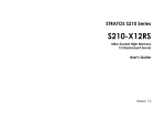
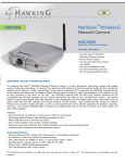
Honeywell Variable Speed Drives – Typical Installation Tips and Notes
1. Drive selection (Obtain motor nameplate information).
a. Drives are sized by voltage and current, not HP. It is acceptable to use a drive with higher HP rating than the
motor name plate if needed. Verify the current capacity of the selected drive meets or exceeds the actual
name plate motor rating and select a larger drive if required.
b. Verify voltage requirements. Drive voltage range must match the motor application.
c. If using single-phase input in lieu of 3-phase power feed, de-rate the drive selection per recommendations
d. Radio Frequency Interference (RFI) and AC line chokes are required in most commercial applications. When
not provided as standard equipment, purchase as an extra cost option. HIGHLY recommended.
e. Verify physical space requirements. Some drive and drive/bypass/filter combinations are large. Allow for
minimum clearances for ventilation and service per drive specifications.
f. Select NEMA-1 chassis for most commercial applications Open-chassis models should be installed in
separate, ventilated cabinets. Select a NEMA-12 drive chassis when installed in harsh environments.
g. Verify ambient operating temperatures do not exceed drive specifications.
h. Allow for extended lead time. Some drives and drive/bypass combinations have extended delivery times.
2. Drive Installation (READ the installation instructions before proceeding!)
a.
b.
c.
d.
e.
f.
g.
h.
Verify drive matches the order. Store and protect drive in a clean and dry location until installed.
Attempt to keep the wire length from the drive to the motor as short as possible to reduce interference.
Provide the proper sized conductors. Do not use conductors that exceed the terminal size
Provide a proper electrical ground per instructions. Failure to do is unsafe and will cause interference.
Do NOT over-torque the electrical connections. They will break! Follow the specifications.
Verify that main power feed is connected to the power INPUT terminals, not the drive output terminals.
It is recommended that the output wires from the drive remain disconnected until after initial startup test.
Wire I/O per application. Typical I/O control requires both analog speed control & digital start/stop signals
• Analog Input #1 is the default selection and is preconfigured as 2-10v (typically terminals 2 & 3)
• Analog Input #2 is preconfigured as 4-20ma (typically terminals 4 & 5)
• Digital Input #1 is preconfigured as Run start/stop. (typically terminals 6 & 8)
3. Configure Drive Parameters (Initial power-up with drive output wires disconnected)
a. CAUTION: If configured for I/O control and with start signal is present, the drive may start unexpectedly.
b. On NXL drives, if using NC-DRIVE program, the serial adapter works with ONLY the Honeywell serial cable.
c. On NXS drives, using the digital display, the start-up wizard may be enabled from SYSTEM menu>
SECURITY submenu> S6.5.3 Start-up wizard.
d. On NXS drives, Select drive application program (NXS drives have 7 built in programs to choose from)
e. Use actual motor name plate information for all basic parameters:
• Set min-max frequencies per the application
• Typical accel/decel times are 10-60 seconds for pumps / 30-120 seconds for fans
• Current LIMIT should be set to 1.5X the motor current name plate full load amps
• Motor cosΦ is equal to motor power factor (from name plate if available).
f. Verify I/O reference parameter. I/O reference selects the input signal location. The default value is 0 (analog
input #1, 2-10v) but may be changed to 1 (analog input #2 ,4-20ma), keypad control (2) or network bus (3).
g. System Menu> Hardware settings> Drive Cooling fan control parameter (if provided) may be changed from
continuous to temperature control to prevent the VFD cooling fan from running continuously.
h. Verify drive auto restart and PID parameters (see pg 2) meet specific application requirements (if applicable)
4. Verify Motor Operation (connect motor leads)
a. Check for faults. A properly configured drive will not generate any fault code during normal operation.
b. If drive without bypass, and motor rotates backwards; swap the terminal connections of any two of the three
drive output wires to reverse.
c. If drive with bypass and motor rotates backwards in the drive mode; swap the terminal connections of any two
of the three drive output wires to reverse.
d. If drive with bypass and motor rotates backwards in the bypass mode; swap the terminal connections of any
two of the three main input wires to reverse – check the drive and reverse the drive output terminal
connections as well if needed.
e. If possible, run motor to full speed and verify actual operating current does not exceed nominal current
parameter setting. Reduce maximum frequency if required to prevent current & temperature faults.
f. Quickly reduce the motor speed. Monitor displayed DC bus voltage. If it rises (motor is acting as a generator)
than increase the deceleration ramp time parameter.
g. Check for stable operation and functionality of all inputs and outputs.
Honeywell VFD tips 1.4.doc
Page 1 of 3
Additional NXL and NXS PID Applications parameters
These are some of the important parameters settings that must be considered when utilizing a drive’s built-in PID application.
These parameters control how the PID loop output (error value 0-100%) changes the drive speed (min to max frequency) in
response to input signal changes and must be adjusted and tuned to meet the requirements and conditions of the actual NXS
or NXL drive installation. (Note: Parameter ID numbers shown may vary with selected application and version used)
□
P2.1.12 – PID Gain (default = 100)
This is the proportional gain (a.k.a. throttling range), as a percentage of input. If the input is a 0-5” wc sensor, a PID
Gain of 50% would result in a output value from 0-100% as the input changed 2.5” of wc beyond setpoint. If a drive is
slow to respond, reduce this value. If a drive ‘hunts’ for stable control, double this value.
□
P2.1.13 – Integral Time (default = 0)
This is the time required to correct the offset between the controlled value and the setpoint. This corrects for errors
which occur using proportional gain alone. Typical values are 100 to 600 seconds. If a drive is slow to respond,
reduce this value. If a drive ‘hunts’ for stable control, double this value.
□
P.2.1.14 – Derivative Time (default = 0)
Recommended to leave at 0 – The default value of 0 is adequate for almost all HVAC applications.
□
P2.1.15 – Sleep Frequency (default = 10 Hz)
This is the drive output frequency point where the drive will enter the ‘sleep mode’ The value is used in conjunction
with sleep delay, wake-up level and wake-up function and is typically used in cooling tower applications to stop a fan
once the condenser water temperature cools. This value MUST be greater than the minimum drive frequency
(P2.1.1) in order to utilize this function.
□
P2.1.16 – Sleep delay (default = 30 seconds)
The time the drive must operate beyond the sleep frequency before it enters the sleep mode.
□
P2.1.17 – Wake Up Level (default = 25%)
This is the % of range of the input sensor which will trigger a drive to wake up when operating in the sleep mode. The
actual sensed value is dependant upon the sensing range of the input device. For example, a 4-20 ma temperature
sensor with a sensing range of 20 to 120’F would have a default wake up point of 45’F (25% of 20-120’F). To set the
wake-up point to 76’F, the Wake Up Level parameter would have to be changed to 56% (76’F is 56% of the sensed
range from 20 to 120’F). Value should be slightly greater in cooling applications (lower in heating applications)
than the PID reference (setpoint %) value in order to provide a differential and prevent short-cycling.
□
P2.1.18 – Wake Up Function (default = 0) Note: If the run contact is NOT closed, the drive will not operate,
regardless of the Wake Up Level
0 = Wake Up drive as input value falls BELOW the wake up level (heating application)
1 = Wake Up drive as input value EXCEEDs the wake up level (cooling application)
□
P2.2.32 – Error value inversion (default = 0, No Inversion) – CRITIAL – MUST MATCH APPLICATION
0 = NO INVERSION = REVERSE ACTING PID (heating application, pressure control)
1 = INVERTED = DIRECT ACTING PID (cooling application, cooling tower fans)
The DISPLAYED input value SCALE, DECIMAL PLACES, and ENGINEERING UNIT may be changed such that the input
sensor displays correctly. Example – A 4-20ma sensor with a range of 20 to 120’F would have a Minimum of 20, a Maximum
of 120, a decimal of 1 and Engineering Units of ‘F
□ P2.2.46 – Displayed Value Minimum (at 0% of range, default = 0)
□ P2.2.47 – Displayed Value Maximum (at 100% of range, default = 100)
□ P2.2.48 – Displayed Value decimal places (default = 1)
□ P2.2.49 – Displayed Value Engineering Units (default = 4, bar. 8=PSI, 16=’F, 0=none)
P3.4 – PID reference (default = 0.0%) – PID SETPOINT as a % of range of the input signal – CRITICAL – MUST MATCH
APPLICATON! For example: If a 4-20 ma input temperature sensor calibrated for 20-120’F is used, and a setpoint of 75’F is
required, the PID reference (a.k.a. setpoint), as a PERCENTAGE of RANGE, would be 55%, which is equal to 75’F.
4 ma
20’F
12 ma
70’F
0%
50%
Honeywell VFD tips 1.4.doc
20 ma
120’F
100%
Page 2 of 3
Using Honeywell NXL/NXS LON option card:
Notes:
•
•
Reference the VACON Lon OPTION C-4 LONWORK USER’s MANUAL
The option card does NOT include a service pin.
o Setting the service pin is a software parameter function from the keyboard:
o Parameter G.7.5.1.1 set to “1” triggers a service pin signal.
Some data requires mathematical correction for proper readings. Other data point values are defined by individual
status bits. Common LON data points with correction factors where applicable:
NvoDrvStatus: Bit 0 (Not Ready = 0, Ready = 1)
NvoDrvStatus: Bit 1 (Stopped = 0, Running = 1)
NvoDrvStatus: Bit 2 (Clockwise = 0, CounterClockwise = 1)
NvoDrvStatus: Bit 3 (No Fault = 0, Fault Active = 1)
NvoDrvStatus: Bit 4 (No Warning = 0, Warning = 1)
NovDrvStatus: Bit 5 (Not at reference speed = 0, At reference speed = 1)
NvoProcessOut1 * 2.0 = Output Frequency (Hz)
NvoProcessOut2 * 200.0 = Output Speed (rpm)
NvoProcessOut3 * 20.0 = Output Current (amps)
NvoProcessOut4 * 20.0 = % Motor Torque
NvoProcessOut5 * 20.0 = % Output Power
NovProcessOut6 * 20.0 = Output Voltage (volts)
NvoProcessOut7 * 200.0 = DC Link Voltage (volts)
Example programming wire sheet
Honeywell VFD tips 1.4.doc
Page 3 of 3