1
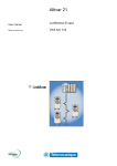
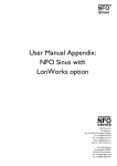
Revision B
Siemens BT300
Lonworks Option Board
Installation and User's Manual
www.sbt.siemens.com
Siemens Industry Inc. • 1
table of contents
Document: DPD01157B
Rev B
Version release date: March 6, 2013
1.
Safety ..................................................................................................................3
1.1
1.2
1.3
Danger .......................................................................................................................................... 3
Warnings....................................................................................................................................... 4
Earthing and earth fault protection................................................................................................ 5
2.
Installation, layout and connections................................................................7
2.1
2.2
2.3
Installation..................................................................................................................................... 7
Prepare for use through LonWorks............................................................................................... 9
Layout ......................................................................................................................................... 12
2.3.1 BT300 OPT-C4 option board......................................................................................... 12
Connections................................................................................................................................ 13
2.4.1 LED indications.............................................................................................................. 13
2.4
3.
4.
LonWorks - General information....................................................................15
LonWorks technical data ................................................................................17
4.1
4.2
4.3
4.4
Quick Setup ................................................................................................................................ 17
Technical data ............................................................................................................................ 17
Physical media and wiring .......................................................................................................... 18
Profiles........................................................................................................................................ 19
4.4.1 Variable speed profile.................................................................................................... 19
5.
Commissioning................................................................................................21
5.1
5.2
I/O and Hardware menu (M5) ..................................................................................................... 21
LonWorks board parameters ...................................................................................................... 21
6.
LonWorks interface .........................................................................................23
6.1
6.2
6.3
6.4
6.5
XIF file......................................................................................................................................... 23
General ....................................................................................................................................... 23
Input Network Variables.............................................................................................................. 25
Output network variables ............................................................................................................ 27
Network configuration variables.................................................................................................. 29
7.
Fault tracing .....................................................................................................31
7.1
Typical fault conditions ............................................................................................................... 31
24-hour support +1-800-877-7545 (Dial 2)
Siemens Industry, Inc. • 2
24-hour support +1 -800-877-7545 (Dial 2)
Safety
1.
Siemens Industry, Inc. • 3
Safety
This manual contains clearly marked cautions and warnings which are intended for your personal safety
and to avoid any unintentional damage to the product or connected appliances.
Please read the information included in cautions and warnings carefully.
The cautions and warnings are marked as follows:
Table 1. Warning signs.
= DANGER! Dangerous voltage
= WARNING or CAUTION
= Caution! Hot surface
1.1
Danger
The components of the power unit of the Siemens BT300 drive are live when the drive is
connected to the primary input voltage. Coming into contact with this voltage is
extremely dangerous and may cause death or severe injury.
The motor terminals U, V, W and the brake resistor terminals are live when the drive
is connected to mains, even if the motor is not running.
After disconnecting the drive from the mains, wait until the indicators on the keypad go
out (if no keypad is attached see the indicators on the cover). Wait 5 more minutes before
doing any work on the connections of the Siemens BT300 drive. Do not open the cover
before this time has expired. After expiration of this time, use a measuring equipment to
absolutely ensure that no voltage is present. Always ensure absence of voltage
before starting any electrical work!
The control I/O-terminals are isolated from the primary input voltage. However, the relay
outputs and other I/O-terminals may have a dangerous control voltage present even
when the Siemens BT300 drive disconnected from mains.
Before connecting the drive to mains make sure that the front and cable covers of Siemens BT300 drive are closed.
During a ramp stop (see the Application Manual), the motor is still generating voltage to
the drive. Therefore, do not touch the components of the drive before the motor has completely stopped. Wait until the indicators on the keypad go out (if no keypad is attached
see the indicators on the cover). Wait an additional 5 minutes before starting any work on
the drive.
24-hour support +800 877-7545 (Dial 2)
Siemens Industry, Inc • 4
1.2
Safety
Warnings
The Siemens BT300 drive is meant for fixed installations only.
Do not perform any measurements when the drive is connected to the mains.
The earth leakage current of Siemens BT300 drives exceeds 3.5mA AC. According to
standard EN61800-5-1, a reinforced protective ground connection must be ensured.
See chapter 1.3.
If the drive is used as a part of a machine, the machine manufacturer is responsible for
providing the machine with a supply disconnecting device (EN 60204-1).
Only spare parts delivered by Siemens can be used.
At power-up, power brake or fault reset the motor will start immediately if the start signal is active, unless the pulse control for Start/Stop logic has been selected.
Furthermore, the I/O functionalities (including start inputs) may change if parameters,
applications or software are changed. Disconnect, therefore, the motor if an unexpected
start can cause danger.
The motor starts automatically after an automatic fault reset if the auto restart function
is activated. See the Application Manual for more detailed information.
Prior to measurements on the motor or the motor cable, disconnect the motor cable
from the drive.
Do not touch the components on the circuit boards. Static voltage discharge may
damage the components.
Check that the EMC level of the drive corresponds to the requirements of your supply
network.
24-hour support +800 877-7545 (Dial 2)
Safety
1.3
Siemens Industry, Inc. • 5
Earthing and earth fault protection
CAUTION!
The Siemens BT300 drive must always be earthed with an earthing conductor connected to the earthing
terminal marked with
.
The earth leakage current of Siemens BT300 exceeds 3.5mA AC. According to EN61800-5-1, one or
more of the following conditions for the associated protective circuit shall be satisfied:
a)
The protective conductor shall have a cross-sectional area of at least 10 mm2 (8 AWG) Cu or
16 mm2 (6 AMG) Al, through its total run.
b)
Where the protective conductor has a cross-sectional area of less than 10 mm2 Cu or 16 mm2
(6 AWG) Al, a second protective conductor of at least the same cross-sectional area shall be
provided up to a point where the protective conductor has a cross-sectional area not less than
10 mm2 (6 AWG) Cu or 16 mm2 (Al.
c)
Automatic disconnection of the supply in case of loss of continuity of the protective conductor.
The cross-sectional area of every protective earthing conductor which does not form part of the supply
cable or cable enclosure shall, in any case, be not less than:
- 2.5 mm2 (14 AWG) if mechanical protection is provided or
- 4 mm2 (12 AWG) if mechanical protection is not provided.
The earth fault protection inside the drive protects only the drive itself against earth faults in the motor
or the motor cable. It is not intended for personal safety.
Due to the high capacitive currents present in the drive, fault current protective switches may not function
properly.
Do not perform any voltage withstand tests on any part of the Siemens BT300 drive.
There is a procedure according to which the tests should be performed. Ignoring this procedure may result in a damaged product.
24-hour support +800 877-7545 (Dial 2)
Siemens Industry, Inc • 6
Safety
24-hour support +800 877-7545 (Dial 2)
Installation, layout and connections
Siemens Industry, Inc. • 7
2.
Installation, layout and connections
2.1
Installation
Open the cover of the variable frequency drive.
1
The relay outputs and other I/O-terminals may have a dangerous control voltage present
even when the Siemens BT300 drive is disconnected from mains.
DANGER
24-hour support +1 800-877-7545 (Dial 2)
Siemens Industry, Inc. • 8
Installation, layout and connections
Make sure that the sticker on the connector of the board says “dv” (dual voltage). This
indicates that the board is compatible with the Siemens BT300 drive. See below:
2
21
22
23
Slot coding
NOTE: Incompatible boards cannot be installed on the Siemens BT300 drive. Compatible boards have a slot coding that enable the placing of the board (see above)
Open the inner cover (1) to reveal the option board slots (D,E) and install the fieldbus
board (2) into slot D or E. D is recommended because it puts the Lonworks communication wire farther from the drive output. Close the inner cover. See Figure below.
1
2
D
E
3
24-hour support +1 800-877-7545 (Dial 2)
Installation, layout and connections
2.2
Siemens Industry, Inc. • 9
Prepare for use through LonWorks
Strip about 15 mm of the fieldbus cable (see specification on page 18) and cut off the
grey cable shield. Remember to do this for both bus cables (except for the last device).
Leave no more than 10 mm of the cable outside the terminal block and strip the cables at
about 5 mm to fit in the terminals. See picture below.
10 (.4)
5 (.2)
BT9189
mm (in.)
4
Also strip the cable now at such a distance from the terminal that you can fix it to the
frame with the grounding clamp. Strip the cable at a maximum length of 15 mm. Do not
strip the aluminum cable shield!
15
in)
(.6
m
m
9188.emf
Then connect the cable to its appropriate terminals on LonWorks Option Board terminal
block.
21 22 23
5
Data 1
Data 2
Fieldbus cable
24-hour support +1 800-877-7545 (Dial 2)
Shield
Siemens Industry, Inc. • 10
Installation, layout and connections
Using the cable clamp included in the delivery of the drive, ground the shield of the
LonWorks cable to the frame of the drive.
Cable clamp
6
If the Siemens BT300 drive is the last device on the bus, the bus termination must be
set. To assure a proper data transmission, termination of the network segments is
required. Depending on the type of network, either one or two terminations are necessary. Free topology network segment requires only one termination whereas a doubly
terminated bus topology requires two.
The jumper X5 on the Siemens BT300 LonWorks board must be set accordingly.
• Use 94 - 105 ohms for bus termination resistance at both ends of the segment.
• 47-ohm termination resistance if using free topology if the drive is in the middle of
the network.
NOTE: In free topology, only one device is terminated.
See also step 10 on Page 11.
7
H3
H2
H1
47
X5
94
no termination
X5
21
22
23
24-hour support +1 800-877-7545 (Dial 2)
Installation, layout and connections
Siemens Industry, Inc. • 11
Unless already done for the other control cables, cut
free the opening on the drive cover for the fieldbus
cable (protection class Type 1/IP21).
NOTE: Cut the opening on the same side you have
installed the board in!
8
Remount the drive cover and run the cable as shown
in picture.
NOTE: When planning the cable runs, remember to
keep the distance between the fieldbus cable and the
motor cable at a minimum of 30 cm (11.8 in.).
9
Fieldbus
cable
The bus termination must be set for the first and the last device of the fieldbus line. See
picture below. See also step 7 on page 13. We recommend that the first device on the
bus and, thus, terminated was the Master device.
10
24-hour support +1 800-877-7545 (Dial 2)
Siemens Industry, Inc. • 12
2.3
Installation, layout and connections
Layout
The Siemens LonWorks Fieldbus Board is connected to the fieldbus through 3-pin pluggable bus connector. The communication with the control board takes place through the standard Siemens Interface
Board Connector.
2.3.1
BT300 OPT-C4 option board
H3
H2
H1
21
22
23
X5
Figure 1.
24-hour support +1 800-877-7545 (Dial 2)
Installation, layout and connections
2.4
Siemens Industry, Inc. • 13
Connections
Table 2. Connections
Signal
Connector
Description
DATA 1
21
Fieldbus connection
DATA 2
22
Fieldbus connection
Shield
23
Fieldbus connection
2.4.1
LED indications
The three LED indications (see Figure 1) next to the connector show the present statuses of the Neuron
(green H3), the LonWorks board (yellow H2) and the Fieldbus Module (green H1). From the user's viewpoint, the first two are the most significant.
Neuron status (H3) GREEN
LED is
OFF
ON
Flashing
Description
State code
Configured
Applicationless and Unconfigured
Unconfigured
4
3
2
Board status LED (H2) YELLOW
LED is
Description
OFF
Option board not activated.
Option board in initialization state waiting for activation command from
ON
the variable frequency drive.
Blinking fast (once/ Option board is activated and in RUN state.
1 s)
Option board is ready for external communication.
Blinking slow
Option board is activated and in FAULT state.
(once/5 s)
Internal fault on option board.
Bus status LED (H1) GREEN
LED is
OFF
ON
Description
Fieldbus module is waiting for parameters from the variable
frequency drive. No external communication.
Fieldbus module is activated.
Parameters received and module activated.
Module is waiting for messages from the bus.
Blinking very fast
Fieldbus module has received a wink request.
for 5s (once/0.2 s)
Blinking fast (once/
Module is activated and receiving messages from the bus.
1 s)
Module is in FAULT state.
Blinking slow (once/
No messages from Net within the watchdog time.
5 s)
Bus broken, cable loose.
24-hour support +1 800-877-7545 (Dial 2)
Siemens Industry, Inc. • 14
Installation, layout and connections
24-hour support +1 800-877-7545 (Dial 2)
LonWorks - General information
3.
Siemens Industry, Inc. • 15
LonWorks - General information
The Siemens BT300 variable frequency drives can be connected to the LonWorks® network using a
fieldbus board. The converter can then be controlled, monitored and programmed from the Host system.
LONWORKS technology has been developed by Echelon Corporation. LONWORKS network is used in
applications like industry and building automation, controlling household electronics, medical instrumentation and many others. The target of the LONWORKS network is to provide a common vendor independent communication network for intelligent devices.
In a LONWORKS network, no central control or master-slave architecture is needed. Nodes on a network communicate with each other using LonTalk® protocol. Inter-operable nodes use Standard Network Variable Types (SNVT) for communicating over the network. The definition of an SNVT includes
units, a range, and an increment. The Siemens option board uses only Standard Network Variable Types
for the data types.
All network variables are either input (data is coming from the network to the device) or output (data is
sent to the network by the device) network variables. When network variables on different nodes on the
network have been bound together by an installation tool, passing of data is automatic between the right
nodes. Only the same type of network variables can be bound together, so it is very important to have
compatible interfaces.
24-hour support +1 800-877-7545 (Dial 2)
Siemens Industry, Inc. • 16
LonWorks - General information
24-hour support +1 800-877-7545 (Dial 2)
LonWorks technical data
4.
LonWorks technical data
4.1
Quick Setup
Siemens Industry, Inc. • 17
Variable frequency drive application.
Choose Fieldbus (Bus/Comm) for the active control place (see Chapter “I/O and Hardware menu (M5)”
on page 21).
Using a Lonworks tool to setup the drive.
1.
Write 100.0 1 to nviDrvSpeedStpt.
2.
The status of the variable frequency drive is RUN and the output frequency is 1.00 * nviDrvSpeedScale
3.
Write 0.0 0 to nviDrvSpeedStpt
4.
The status of the variable frequency drive is STOP.
If nvoDrvStats bit 3 = 1, the status of the variable frequency drive is FAULT.
NOTE: Commissioning of the Lon option requires a third party tool such as NLUtil or LonMaker.
To transmit a service pin for identification on a LonWorks network, complete the following changes:
NOTE: The Lon Option card can be installed in slot D or Slot E. The menu structure used below assumes
that slot D was used.
Navigate:
Main Menu > I/O and Hardware (M5) > OPTC4 (M5.2) > Parameters (M5.2.3 >
Service Pin (M5.2.3.1) > Edit > Set to a value of 1.
Then complete the NLUtil or LonMaker commissioning.
For commanding of Run/Stop via LonWorks complete the following (in addition to the Monitoring
steps above):
Navigate:
Main Menu > Quick Setup (M1) > Ctrl. Place Auto (M1.15) > Edit > Select FieldBusCTRL
For commanding of Speed Reference via LonWorks complete the following (in addition to the monitoring steps above):
Navigate:
Main Menu > Quick Setup (M1) > I/O A Ctrl Ref (M1.10) > Edit > Select Fieldbus
4.2
Technical data
Connections and
communications
Environment
Safety
Table 3. Lonworks technical data.
Interface
Pluggable connector (5 mm)
Channel type
TP/FT-10
Communication cable
Shielded Twisted Pair
Baud rate
78 Kbit/s
Ambient operating tem-10°C…50°C
perature
Storing temperature
-40°C…70°C
Humidity
<95%, no condensation allowed
Altitude
Max. 1000 m
Vibration
0.5 G at 9…200 Hz
Fulfills EN50178 standard
24-hour support +1 800-877-7545 (Dial 2)
Siemens Industry, Inc. • 18
4.3
LonWorks technical data
Physical media and wiring
LONWORKS networks can be implemented on many different physical media. The Siemens OPT-C4
option board is equipped with an FT-X1 transceiver supporting the Free Topology transformer coupled
network, which allows the network wire to be connected as bus, star, loop or combination thereof. This
media reaches a communication speed of 78kBits/s. The FT-X1 transceiver is compatible with Echelon's LPT-10 Link Power Transceiver, and these transceivers can communicate with each other on a
single twisted pair cable.
Termination
Termination
Figure 2. Doubly terminated bus topology
Use the doubly terminated bus topology. However, also singly terminated, star or loop topologies can be
used with the OPT-C4 option board.
Up to 64 FTT-10 transceiver nodes are allowed per network segment. The individual segments can be
connected together by a router. See Table 3 for possible cable types and cable lengths for the FTT-10.
Even if unshielded cable types can be used with this type of transceiver, it is still highly recommended
to use only shielded cables with variable frequency drives. Attention should be paid to proper grounding
of the shield to ensure bus operation. Grounding of the shield should be done at both ends of the cable.
Table 4. LonWorks FLN Trunk Wire Types and Maximum Length.
Maximum length per
Wire type
LonWorks FLN segment
No. 22 AWG Level 4 per NEMA standards
500 m (1,640 feet)
Table 5. Network Wire Length vs. Gauge.
Free Topology
Bus
Total Wire
Distance
Max. Node
to Node
Distance
Total Wire Distance
Max node to
Node
Distance
500 m
(1,640 ft)
500 m
(1,640 ft)
2,700 m (8,858 ft)
Max. Stub Length
3 m (10 ft)
2,700 m
(8,858 ft)
500 m
(1,640 ft)
400 m
(1,312 ft)
2,700 m (8,858 ft) Max.
Stub Length
3 m (10 ft)
2,700 m
(8,858 ft)
22 AWG (0.34 mm)
Level 43
500 m
(1,640 ft)
400 m
(1,312 ft)
1,400 m (4,593 ft)
Max. Stub Length
3 m (10 ft)
1,400 m
(4,593 ft)
CAT 5 TP / TIA 568A
Category 5
cable/24AWG (0.5mm)
450 m
(1,476 ft)
250 m
(820 ft)
900 m
(2,953 ft)
900 m
(2,953 ft)
Wire Gauge
16 AWG (1.5 mm)
TPControl/Signaling
Grade1
16 AWG (1.5 mm)
TPGeneral Purpose
Grade2
1. Control/Signaling Grade /16 AWG = Single twisted pair, stranded 19/29, unshielded, Teflon insulation and
jacket High Temperature 150°C Max.
2. General purpose-grade /16 AWG = single twisted pair, stranded 19/29 unshielded, PVC Insulation andjacket Medium temperature 80°C Max.
3. Level IV cable per NEMA standards (Not equivalent to EIA/TIA Level 4 cable)
24-hour support +1 800-877-7545 (Dial 2)
LonWorks technical data
4.4
Siemens Industry, Inc. • 19
Profiles
LonMark Functional Profiles describe in detail the application layer interface, including the network variables, configuration properties, and default and power-up behaviors required on LonMark devices for
specific, commonly used control functions.
4.4.1
Variable speed profile
Leading manufacturers of drive technology have jointly defined the LonMark profile. The profile specifies
how to parameterize the drives and how to transmit setpoints and actual values. This allows drives from
different vendors to be replaced. The profile contains specifications for speed control and positioning. It
specifies the basic drive functions while leaving sufficient freedom for application-specific expansions
and further development.
24-hour support +1 800-877-7545 (Dial 2)
Siemens Industry, Inc. • 20
LonWorks technical data
24-hour support +1 800-877-7545 (Dial 2)
Commissioning
5.
Siemens Industry Inc. • 21
COMMISSIONING
Please read first the commissioning chapter in the Siemens BT300 HVAC Installation manual
(DPDP1148B).
5.1
I/O and Hardware menu (M5)
The I/O and Hardware menu makes it possible for the user to
•
•
•
see what expander boards are connected to the control board.
reach and edit the parameters associated with the expander board.
retrieve Software information.
5.2
Code
M5.x.3.1
LonWorks board parameters
Parameter
Service Pin
Min
0
24-hour support +1 800-877-7545 (Dial 2)
Max
1
Unit
Default
0
ID
Description
Setting this parameter to
a value of 1 broadcasts a
service pin message to
the network.
Siemens Industry, Inc. • 22
Commissioning
24-hour support +1 800-877-7545 (Dial 2)
LonWorks interface
6.
Siemens Industry, Inc. • 23
LONWORKS INTERFACE
Features of the LonWorks interface:
• Direct control of the Siemens BT300 drive (e.g. Run, Stop, Direction, Speed reference, Fault
reset)
• Full access to all the Siemens BT300 drive parameters
• Monitor the Siemens BT300 drive’s status (e.g. Output frequency, Output current, Fault code)
6.1
XIF file
XIF file tells network-management tools how to communicate and recognize a device. It contains Program ID, NVs, CPs, functional blocks, etc.
6.2
General
Node Object:0
nviRequest
nv1 SNVT_obj_request
Mandatory
Network
Variables
nv2
nv oStatus
SNVT_obj_s tatus
Figure 3. The node object diagram.
24-hour support +1 800-877-7545 (Dial 2)
Siemens Industry, Inc. • 24
LonWorks interface
Variable Speed Motor drive:
6010
nv1
nv iDrvSpeedStpt
SNVT_obj_request
nv2
nviDrvSpeedScale
SNVT_levPercent
Mandatory
Network
Variables
Optional
Network
Variables
nvoDrvSpeed
SNVT_levPercent
nv4
nv1
nviRequest
SNVT_obj_request
nv1
nviRequest
SNVT_obj_request
nv1
nviRequest
SNVT_obj_request
Configuration properties
nc50 nciMaxSpeed
nc53 nciMinSpeed
nc48 nciRcvHrtBt
nc49 nciSndHrtBt
nc52 nciMinOutTm
nc158 nciNmlSpeed
nc158 nciNmlFreq
nc160 nciRampUpTm
nc161 nciRampDownTm
nc162 nciDrvSpeedScale
Manufacturer
Defined
Network
Variables
nv8
nviRstFault
SNVT_swit ch
nv9
nviCrlCntr
SNVT_swit ch
nv10
nviProc essIN1
SNVT_lev_percent
nv11
nviProcessIN2
SNVT_lev_percent
nv30
nv oProcessO ut1
SNVT_lev_percent
nv12
nviProcessIN3
SNVT_lev_percent
nv31
nv oProcessOut2
SNVT_lev_percent
nv13
nviProcessIN4
SNVT_lev_percent
nv32
nvoProces sOut 3
SNVT_lev_percent
nv14
nviProcessI N5
SNVT_lev_perc ent
nv33
nvoProcessOut4
SNVT_lev_percent
nv15
nv iProcessIN6
SNVT_lev_percent
nv34
nvoProces sOut 5
SNVT_lev_percent
nv16
nviProcessIN7
SNVT_lev_percent
nv35
nvoProces sOut 6
SNVT_lev_percent
nv17
nviProcessIN8
SNVT_lev_percent
nv36
nvoProcessOut7
SNVT_lev_perc ent
nv37
nvoProcessOut8
SNVT_lev_perc ent
nv27
nvoDrvSt atus
SNVT_state
nv28
nvoDrvStatus
SNVT_stat e
nv29
nvoActFault
SNVT_count
nv18
nviDigitalIn1
SNVT_switch
nv19
nviDigitalIn2
SNVT_switch
nv38
nvoDigitalOut1
SNVT_swit ch
nv20
nviDigitalI n3
SNVT_swit ch
nv39
nvoDigitalOut2
SNVT_swit ch
nv21
nviDigitalIn4
SNVT_switch
nv40
nvoDigitalOut3
SNVT_switch
nv22
nviDigitalIn5
SNVT_switch
nv41
nv oDigitalOut 4
SNVT_switch
nv23
nviDigitalIn6
SNVT_switch
nv42
nvoDigitalOut5
SNVT_switch
nv24
nv iDigitalIn7
SNVT_switch
nv43
nv oDigitalOut 6
SNVT_switch
nv25
nviDigitalIn8
SNVT_switch
nv44
nvoDigitalOut7
SNVT_switch
nv45
nviParCmd
SNVT_reset
nvoDigitalOut8
SNVT_switch
nv26
nv46
nvoParResp
SNVT_preset
Figure 4. The Variable Speed Motor Drive object diagram
24-hour support +1 800-877-7545 (Dial 2)
LonWorks interface
6.3
Siemens Industry, Inc. • 25
Input Network Variables
Table 6. Input network variables.
Function
Variable Name
SNVT Type
Node Object request
nviRequest
SNVT_obj_request
Driver speed setpoint
nviDrvSpeedStpt
SNVT_switch
Driver set point speed
scaling
nviDrvSpeedScale
SNVT_lev_percent
Min. value Max. value
n/a
n/a
-163.840%
163.830%
Reset fault
nviRstFault
SNVT_switch
n/a
n/a
Clear kWh trip or Drive
total running hours trip
counters
nviClrCntr
SNVT_switch
1
2
Process In Data
nviProcessIn1..8
SNVT_lev_percent
0
65535
Digital Inputs
nviDigitalIn1..8
SNVT_switch
0
4
nviParCmd
SNVT_preset
n/a
n/a
Parameter Set
nviRequest
This input network variable provides the mechanism to request a particular mode for the Node object or
the Variable Speed Motor Drive object within a node. Supported requests are RQ_NORMAL, RQ_UPDATE_STATUS, RQ_CLEAR_STATUS, RQ_REPORT_MASK, RQ_DISABLED, RQ_ENABLE and
RQ_CLEAR_ALARM.
nviDrvSpeedStpt
This input network variable provides control and a low resolution speed setpoint.
Table 7.
State
Value
Command
0
NA
Stop
1
0
0%
1
1 to 200
0.5 to 100%
1
201 to 255
100.0%
0xFF
NA
Auto
nviDrvSpeedScale
This input netork variable provides scaling for nviDrvSpeedStpt. Negative values indicate a motor direction in reverse. For example, if the nviDrvSpeedStpt value is 50% and nviDrvSpeedScale -150%, then
the actual speed setpoint is -75%, or 0.75 times the nominal speed in reverse direction. The valid range
is -163,840% to 163,830. The value 0x7FFF (+163,835%) will be handled as an invalid value. Default
value is determined by nciDrvSpeedScale. This value will be adopted at power-up and in case of not
receiving an update within the specified Receive Heartbeat time.
nviRstFault
This input network variable provides a fault reset. Setting value 1 for State and a non-zero value for Value will reset an active fault in the Siemens BT300 drive. Default value is 0; 0
Table 8. Fault table.
State
Value
Command
0
any
no action (0; 0)
1
0
no action (0; 1)
1
>0
reset fault (200 ; 0)
-1(0xFF)
any
invalid (no action)
24-hour support +1 800-877-7545 (Dial 2)
Siemens Industry, Inc. • 26
LonWorks interface
nviClrCntr
This input network variable provides a mechanism to clear the kWh trip counter or the drive total running
hours trip counter.
1 = MWh trip counter
2 = Operation day trip counter
nviProcessInl..8
These input network variables are sent directly to the application (see more detailed explanation in chapter 6.5 Process data) The valid range is 0 to 65535 (-163,840 to 163,835).
nviDigitalIn1 ..8
These input network variables are sent directly to the application (see more detailed explanation in chapter 6.5 Process data) Default value is 0; 0.
Table 9.
State
Value
Command
0
any
off (0; 0)
1
0
off (0; 1)
1
>0
on (200 ; 0)
-1(0xFF)
any
invalid (no action)
nviParCmd
This input network variable is used to read and write the parameters. Parameter addresses are determined in the application. Every parameter and actual value has been given an ID number in the application. The ID numbering of the parameter as well as the parameter ranges and steps can be found in
the application manual. The parameter value must be given without decimals. Find the ID numbers of
each parameter/actual value in the application manual. The ID numbers are grouped as follows:
Table 10.
Parameter ID
Group
0
Not used
1 … 98
Actual Values
37
Active Fault Code
100
Not used
101… 899
Parameter
900 … 999
Reserved
1000
Not used
1001…1999
Parameter
Description
Reserved for LonWorks board
internal usage
Examples
Data format in examples is:
- learn selector <byte(3) byte(2) byte(1) byte(0)> day hour minute second millisecond
x = meaningless
Example1
Write to parameter number 102 (Max frequency "HVAC Application par. ID102") value 4500 (45Hz).
Write command to nviParSet
- LN_LEARN_CURRENT 102 <x x 11 94> x x x x
24-hour support +1 800-877-7545 (Dial 2)
LonWorks interface
Siemens Industry, Inc. • 27
If the write command is successful then nvoParOut value is
- LN_LEARN_CURRENT 102 <0 0 11 94> 0 0 0 0
If the write command fails then nvoParOut value is
- LN_NUL 102 <0 0 11 94> 0 0 0 0
Example2
Read parameter number 112 (Nominal speed of the motor "HVAC Application par. ID112") default value
1440 (1440 rpm).
Read command to nviParSet
- LN_RECALL 112 <x x x x> x x x x
If the read command is successful then nvoParOut value is
- LN_RECALL 112 <0 0 5 A0> 0 0 0 0
If the read command fails then nvoParOut value is
- LN_ LN_NUL 112 <0 0 0 0> 0 0 0 0
6.4
Output network variables
Table 11. Output network variables
Function
Variable Name
Node Object status
SNVT Type
Min. Value
Max. Value
nvoStatus
SNVT_obj_status
Drive speed feedback
nvoDrvSpeed
SNVT_lev_percent
-163.840%
+163.830%
Actual motor current
nvoDrvCurnt
SNVT_amp
0.0A
3276.7A
nvoDrvPwr
SNVT_power_kilo
0,0 kW
6553,5 kW
SNVT_time_hour
0h
65535
Actual drive power
Drive total running hours nvoDrvRunHours
Status word
nvoDrvStatus
SNVT_state
n/a
n/az
kWh trip counter
nvoDrvEnrgy
SNVT_elect_kwh
0kWh
65535kWh
Active fault code
nvoActFault
SNVT_count
0
41
nvoProcessOut1..8
SNVT_ lev_percent
0
65535
nvoDigitalOut1..8
SNVT_switch
0
4
nvoParResp
SNVT_preset
Process Out
Digital Out
Parameter Out
nvoStatus
This output network variable reports the status for Node object or Variable Speed Motor Drive object
Table 12.
Field
Description
object_id
ID of object within node
invalid_id
1 means requested ID is not implemented in this node
invalid_request
1 means request for unimplemented function
disabled
1 means object disabled
electrical_fault
1 means drive is faulted
in_alarm
1 means drive is in alarm
report_mask
1 means status is an event mask
nvoDrvSpeed
This output network variable provides the speed of the drive as a percentage of the nominal speed.
24-hour support +1 800-877-7545 (Dial 2)
Siemens Industry, Inc. • 28
LonWorks interface
nvoDrvCurnt
This output network variable provides the drive output current in amperes.
nvoDrvPwr
This output network variable provides the drive output power in kW.
nvoDrvRunHours
This output network variable provides the drive resettable operation time counter for the motor in running
hours. The maximum value for used SNVT is 65535 h. On the variable frequency drive, the value can
go much higher. If the counter exceeds the SNVT's maximum value, the network variable stays at its
maximum. In such cases, the real value can be seen on the Siemens BT300 operating keypad.
nvoDrvStatus
This output network variable provides the drive status.
Table 13. Status word bit descriptions
Bit
Description
Value = 0
Value = 1
0
Not Ready
Ready
1
FC stopped
Running
2
Clockwise
Counterclockwise
3
No fault
Fault active
4
No warning
Warning active
5
Reference not Actual value
Reference = Actual value
nvoDrvEnrgy
This output network variable provides the drive resettable energy consumption counter. The maximum
value for used SNVT is 65535 kWh. On the frequency converter the value can go much higher. If the
counter exceeds the SNVT's maximum value, the network variable stays at its maximum. In such cases
the real value can be seen on the Siemens BT300 operating keypad.
nvoActFault
This output network variable provides the drive active fault code. If the value is 0 the frequency converter
has no fault. See the fault code list in the Siemens BT300 drive User's Manual for fault identification.
nvoProcessOut1..8
These output network variables are sent directly from the application (see more detailed explanation in
chapter 6.5 Process data) The valid range is 0 to 65535 (-163,840 to 163,835)
nvoDigitalOut1 ..8
These output network variables are sent directly from the application (see more detailed explanation in
chapter 6.5, Process data).
Table 14.
state
value
command
0
0
off (0; 0)
1
200 (0xC8)
on (200; 1)
any
invalid (NULL)
-1 (0XfF)
nvoParResp
explained in chapter nviParSet.
24-hour support +1 800-877-7545 (Dial 2)
LonWorks interface
6.5
Siemens Industry, Inc. • 29
Network configuration variables
Table 15. Network configuration variables.
Function
Variable Name
SNVT Type
Maximum motor speed
nciMaxSpeed
SCPTmaxSetpoint
Minimum motor speed
nciMinSpeed
SCPTminSetpoint
Receive heartbeat time
nciRcvHrtBt
SCPTmaxRcvTime
Send heartbeat time
nciSndHrtBt
SCPTmaxSndTime
Minimum output time
nciMinOutTime
SCPTminSndTime
Nominal motor speed in RPM
nciNmlSpeed
SCPTnomRPM
Nominal motor frequency
nciNmlFreq
SCPTnomFreq
Minimum ramp up time
nciRampUpTm
SCPTrampUpTm
Minimum ramp down time
nciRampDownTm
SCPTrampDownTm
Default value for nviDrvSpeedScale
nciRampDownTm
SCPTdefScale
nciMaxSpeed
This configuration property is used to define the maximum speed of a motor. The value is entered as a
percentage of nominal speed in RPM, as defined by the Nominal Speed (nciNmlSpeed) configuration
value. The value of the maximum speed must be validated against the value of the minimum speed as
follows:
-163.840 < minimum speed < maximum speed < 163.830
nciMinSpeed
This configuration property is used to define the minimum speed of the motor. The value is entered as
a percentage of nominal speed in RPM, as defined by the Nominal Speed (nciNmlSpeed) configuration
value. The value of the minimum speed must be validated against the value of the maximum speed as
follows:
-163.840 < minimum speed < maximum speed < 163.830
nciRcvHrtBt
This configuration property is used to control the maximum time that elapses after the last update of the
network variables nviDrvSpeedStpt or nviDrvSpeedScale before the VSD object starts to use the default
values.
nciSndHrtBt
This configuration property defines the maximum period that expires before the network variables
nvoDrvSpeed, nvoDrvCurnt and nvoDrvPwr are automatically updated.
nciMinOutTime
This configuration property defines the minimum period of automatic network variable transmission.
nciNmlSpeed
This configuration property is used to provide the nominal speed of the motor in RPM. This value is necessary to determine the minimum and maximum speeds for the motor, based on the configuration properties nciMinSpeed, nciMaxSpeed (entered as a percentage of nominal speed).
nciNmlFreq
This configuration property is used to provide the nominal frequency for the motor.
nciRampUpTm
Defines the acceleration time for the Siemens BT300 drive. The valid range is 0.0 to 6,553.4 sec (0.1
sec).
24-hour support +1 800-877-7545 (Dial 2)
Siemens Industry, Inc. • 30
LonWorks interface
nciRampDownTm
Defines the deceleration time for the Siemens BT300 drive. The valid range is 0.0 to 6,553.4 sec (0.1
sec).
nciDrvSpeedScale
This configuration property is used as the default value for nviDrvSpeedScale. This value will be adopted
at power-up and in case no input variable within the specified Receive Heartbeat time is received.
24-hour support +1 800-877-7545 (Dial 2)
Fault tracing
7.
Siemens Industry, Inc. • 31
FAULT TRACING
When an unusual operating condition is detected by the drive control diagnostics, the drive initiates a
notification visible, for example, on the keypad. The keypad will show the ordinal number of the fault, the
fault code and a short fault description.
The fault can be reset with the Reset button on the control keypad or via the I/O terminal. The faults are
stored in the Fault history menu which can be browsed. You can find the different fault codes in the table
below. This fault table indicates only the faults related to the fieldbus in use.
The LonWorks option board status LEDs are described in more detail in Chapter 2.4.1
NOTE: When contacting Siemens because of a fault condition, contact Technical Support at 1-800-8777545 (Dial 2). Always write down all texts and codes on the keypad display and send a description of the
problem together with the Drive Info file.
7.1
Typical fault conditions
Table 16. Typical fault conditions.
Fault condition
Termination
resistor
Possible cause
Install termination resistors
Missing or excessive termination resistor. at both ends of the fieldbus
line.
•
Cabling
Grounding
Connections
Parameter
Remedy
•
•
Supply or motor cables are located
too close to the fieldbus cable
Wrong type of fieldbus cable
Too long cabling
Inadequate grounding.
Faulty connections.
• Excessive stripping of cables
• Conductors in wrong terminals
• Too loose connections of conductors
•
•
•
•
Faulty address
Overlapping slave addresses
Wrong baud rate
Wrong control place selected
24-hour support +1 800-877-7545 (Dial 2)
Ensure grounding in all
points on the net
Siemens Industry, Inc. • 32
Fault tracing
24-hour support +1 800-877-7545 (Dial 2)
Siemens Industry, Inc.
Building Technologies Division
1000 Deerfield Parkway
Buffalo Grove, IL. 60089-4513
USA
1-847-215-1000
DPD01157B
Part No. DPD01157B
Copyright © 2013 Siemens Industry, Inc.
www.sbt.siemens.com