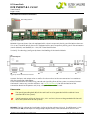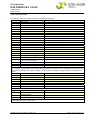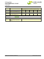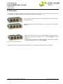
1
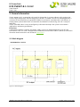
DC Power Rack DCR PSR327-8.1 LV/HV USER MANUAL UM_DCR_PSR327_8.1_E_R3.0 DC Power Rack DCR PSR327-8.1 LV/HV User Manual Page 2 (28) Notes to this manual ATTENTION! Read this manual very carefully before installing and commissioning the DC power rack. This manual is a part of the delivered DC power rack. Familiarity with the contents of this manual is required for installing and operating the DC power rack. The rules for prevention of accidents for the specific country and the general safety rules in accordance with IEC 364 must be observed. The function description in this manual corresponds to the date of publishing. Technical changes and changes in form and content can be made at any time by the manufacturer without notice. There are no obligations to update the manual continually. The unit is manufactured in accordance with applicable DIN and VDE standards such as VDE 0106 (part 100) and VDE 0100 (part 410). The CE marking on the unit confirms compliance with EU standards 2006-95-EG (low voltage) and 2004-108-EG (electromagnetic compatibility) if the installation and operation instructions are followed. Supplier: FAX Email Internet ELTEK VALERE DEUTSCHLAND GmbH GB Industrial Schillerstraße 16 D-32052 Herford + 49 (0) 5221 1708-210 + 49 (0) 5221 1708-222 [email protected] http://www.eltekvalere.com Changes and errors excepted. 2009. ELTEK VALERE DEUTSCHLAND GmbH. All rights reserved. ©2009. ELTEK VALERE DEUTSCHLAND GmbH. UM_DCR_PSR327_8.1_E_R3.0 DC Power Rack DCR PSR327-8.1 LV/HV User Manual Page 3 (28) The current revision status of this user manual is the following: Revision: 3.0 Date: 2010-05-11 Revision Description of change Writer Date 00 Preliminary version RTH 2008-02-01 01 First edition RTH 2008-02-15 02 Minor addition in the section “rear side connection” RTH 2008-02-28 RTH 2008-03-04 RTH 2008-06-03 RTH 2008-12-18 03 04 1.0 “Recommended wire cross section” for the output inserted Index of figures inserted, minor text modifications, section “Can-Bus termination” reworked. Designation of the alarm relay outputs corrected, new revision status numbering (X.X) introduced. 2.0 Section “Extensions” added. RTH 2009-06-05 2.1 Minor text modifications included. RTH 2009-12-17 3.0 Section 3.2.7 "Protection against electric shock at the DC output connectors" inserted. RTH 2010-05-11 ©2009. ELTEK VALERE DEUTSCHLAND GmbH. UM_DCR_PSR327_8.1_E_R3.0 DC Power Rack DCR PSR327-8.1 LV/HV User Manual Page 4 (28) Table of Contents 1A. SAFETY INSTRUCTIONS .............................................................................................................6 1B. ELECTRIC WASTE DISPOSAL......................................................................................................6 2. GENERAL INFORMATION ...............................................................................................................7 2.1 Block diagram...........................................................................................................................................7 2.2 Possible rack configurations ................................................................................................................8 2.3 Perspective view .....................................................................................................................................9 2.4 Available options and required equipment.......................................................................................9 2.5 Cooling and air flow direction............................................................................................................ 10 3. HANDLING ..................................................................................................................................... 11 3.1 Storage ................................................................................................................................................... 11 3.2 Commissioning...................................................................................................................................... 11 3.2.1 Communication interface............................................................................................................................. 12 3.2.2 Can-Bus termination...................................................................................................................................... 12 3.2.3 CAN address designation............................................................................................................................. 13 3.2.4 Fitting of the modules................................................................................................................................... 13 3.2.5 Rear view/electric connectors ................................................................................................................... 14 3.2.6 Connection table ............................................................................................................................................ 15 3.2.7 Protection against electric shock at the DC output connectors....................................................... 17 3.2.8 Schematic diagram (example of use) ....................................................................................................... 18 3.2.9 Connection board ........................................................................................................................................... 19 4. MAINTENANCE ............................................................................................................................. 21 5. TECHNICAL SPECIFICATIONS .................................................................................................... 22 5.1 Dimensional Drawings:........................................................................................................................ 24 6. EXTENSIONS................................................................................................................................. 25 6.1 Schematic diagram DCR PSR327-8.1 and -10.8 connected in parallel ................................... 26 7. YOUR NOTES ................................................................................................................................ 27 ©2009. ELTEK VALERE DEUTSCHLAND GmbH. UM_DCR_PSR327_8.1_E_R3.0 DC Power Rack DCR PSR327-8.1 LV/HV User Manual Page 5 (28) Index of Figures Figure 1) - Block diagram ..................................................................................................................................................7 Figure 2) - DC power rack fully equipped......................................................................................................................9 Figure 3) - Rack air flow.................................................................................................................................................. 10 Figure 4) - Rack mounting points................................................................................................................................. 11 Figure 5) - Front view of the empty rack ................................................................................................................... 12 Figure 6) - CAN-Bus termination switches ................................................................................................................ 12 Figure 7) - Rotary switch= CAN address selector ................................................................................................... 12 Figure 8) - Rear view........................................................................................................................................................ 14 Figure 9) - Rear electrical connectors ........................................................................................................................ 14 Figure 10) - Fitting of the covers ................................................................................................................................. 17 Figure 11a) - Final fitting position of the covers...................................................................................................... 17 Figure 11b) - Fixing the cover by cable strap ........................................................................................................... 17 Figure 12) - Schematic diagram ................................................................................................................................... 18 Figure 13) - Top view of the connection board ........................................................................................................ 19 Figure 14) - Rack dimensions........................................................................................................................................ 24 Figure 15) - System extension ..................................................................................................................................... 25 Figure 16) - DCR PSR327-10.8 and DCR PSR327-8.1 connected in parallel...................................................... 26 ©2009. ELTEK VALERE DEUTSCHLAND GmbH. UM_DCR_PSR327_8.1_E_R3.0 DC Power Rack DCR PSR327-8.1 LV/HV User Manual Page 6 (28) 1A. Safety Instructions Warning! Because several components of operating electric devices are charged by dangerous voltage, the improper handling of electric devices may be the cause of accidents involving electrocution, injury, or material damages. Operation and maintenance of electrical devices must be performed by qualified skilled personnel such as electricians in accordance with EN 50110-1 or IEC 60950. Install the unit only in areas with limited access to unskilled personnel. Before starting work, the unit must be disconnected from mains. Make sure that the unit is earthed. Only spare parts approved by the manufacturer must be used. 1B. Electric Waste Disposal Separate collection is the precondition to ensure specific treatment and recycling of waste electrical and electronic equipment and is necessary to achieve the chosen level of protection of human health and the environment. In the case of waste disposal of your discarded equipment we recommend to contact a waste management company. ©2009. ELTEK VALERE DEUTSCHLAND GmbH. UM_DCR_PSR327_8.1_E_R3.0 DC Power Rack DCR PSR327-8.1 LV/HV User Manual Page 7 (28) 2. General information The DC power rack is a connection unit ready for integration in system cabinets with standard 19’’ frame. A high voltage (HV) and low voltage (LV) version is available. The unit can be equipped with a maximum of three rectifiers of type PSR327 (PSR312) and one DC controller UPC3 and delivers an output power up to 8100W. After safe mechanical and electrical connecting, the unit is ready for operation. The DC controller UPC3 is easy to configure by software and adapts the system to customer’s applications and battery parameters. Extensions: If more output power is required, the power supply system can be extended with racks of type DCR PSR327-10.8. This rack is designed to be fitted with four rectifiers PSR327 (PSR312). For more information about extensions see section 6. “Extensions”. 2.1 Block diagram DCR PSR327-8.1 LV/HV Figure 1) - Block diagram ©2009. ELTEK VALERE DEUTSCHLAND GmbH. UM_DCR_PSR327_8.1_E_R3.0 DC Power Rack DCR PSR327-8.1 LV/HV User Manual Page 8 (28) 2.2 Possible rack configurations One up to three rectifiers PSR327 (PSR312) with output voltages according to the table below, plus one obligatory DC controller UPC3 can be integrated into one rack. Make sure to use the correct UPC3 unit in accordance with the output voltage of the used rectifiers (see the following table). DCR PSR327-8.1 LV DCR PSR327-8.1 HV Article code of the rack 102-327-318.LV01 102-327-318.HV01 Input voltage = 230VAC Designation of the rack For rectifier/ output voltage Necessary type of DC controller UPC3//Article code PSR312/24VDC UPC3-24V//301-003-498.02 PSR327/48VDC PSR327/60VDC UPC3-48/60V//301-003598.02 PSR327/110VDC UPC3-110V//301-003-798.02 PSR327/220VDC UPC3-220V//301-003-898.02 Output power of the rack, equipped with PSR312: Number of installed Rectifiers (PSR312) Output power (without redundancy) Output power (n + 1) Output power (n + 2) 1 1200W --- --- 2 2400W 1200W --- 3 3600W 2400W 1200W Output power of the rack, equipped with PSR327: Number of installed Rectifiers (PSR327) Output power (without redundancy) Output power (n + 1) Output power (n + 2) 1 2700W --- --- 2 5400W 2700W --- 3 8100W 5400W 2700W ©2009. ELTEK VALERE DEUTSCHLAND GmbH. UM_DCR_PSR327_8.1_E_R3.0 DC Power Rack DCR PSR327-8.1 LV/HV User Manual Page 9 (28) 2.3 Perspective view 1 2 1 3 3 Figure 2) - DC power rack fully equipped with three rectifiers PSR327 and one DC controller UPC3. Fastening elements according to figure 2) 1 2 3 Four screws M6 to fix the sub rack to the frame of the system cabinet Two adjustable assembly brackets (on the left and right side) to fix the sub rack to the rear frame of the system cabinet. Two captive screws are used for each module to secure it to the sub rack Comment Component parts of the sub rack Component parts of the modules 2.4 Available options and required equipment Description Article code DCC-CB1; connection board (with MSTB screw terminals), required to connect all measuring, control and signalling wires over the backplane of the subrack to the DC controller UPC3, see section 3.2.9 “Connection Board” Cover plate (with handle) to cover empty slots, 1/4 x 19’’, 3U, colour RAL 7035 302-DCC-CB1.00 (Included in delivery of the sub rack) 881-MEC-BPL.03.21.B Temperature sensor KTY81-220 T092 with cable of 4m length 302-TMP-KTY.04 CAN-Bus connection cable, length 0.5m (other lengths available) 880-KAB-CAN.05 Extension rack DCR PSR327-10.8 for four rectifiers PSR327 (312), see section 6. “Extensions”. For 24-60VDC: 102-327-408.LV01 For 110-220VDC: 102-327-408.HV01 ©2009. ELTEK VALERE DEUTSCHLAND GmbH. UM_DCR_PSR327_8.1_E_R3.0 DC Power Rack DCR PSR327-8.1 LV/HV User Manual Page 10 (28) 2.5 Cooling and air flow direction The PSR327 (312) units are cooled with internal fans. The airflow is from the front to rear side. The fans are monitored and speed-controlled dependent on module temperature. To provide sufficient air flow, a minimum space (see figure 3, item “A”) of 50 mm is required between the backplane of the rack and the rear cabinet wall as well as an unobstructed supply of air to the front of the modules. Figure 3) - Rack air flow ©2009. ELTEK VALERE DEUTSCHLAND GmbH. UM_DCR_PSR327_8.1_E_R3.0 DC Power Rack DCR PSR327-8.1 LV/HV User Manual Page 11 (28) 3. Handling 3.1 Storage Power racks must be stored in a dry, dust free environment with a storage temperature in accordance with the specific technical data (see section 5). 3.2 Commissioning 1. Carefully unpack the unit and mount it on your power supply cabinet with 4 screws M6 (1) at the front side. 2. Adjust the assembling brackets (2) on the left and right side of the rack with the relevant nuts of the rear cabinet frame and tighten the brackets with 4 screws M6 (3) as shown in figure 4). 1 3 1 2 Figure 4) - Rack mounting points REMARK: Before assembling the modules, the following settings have to be checked and if necessary must be done on the empty rack: 1. CAN-Bus termination 2. CAN address designation For details, see the following sections. ©2009. ELTEK VALERE DEUTSCHLAND GmbH. UM_DCR_PSR327_8.1_E_R3.0 DC Power Rack DCR PSR327-8.1 LV/HV User Manual Page 12 (28) Figure 5) - Front view of the empty rack Slot1 PSR3xx Slot2 PSR3xx Figure 6) - CAN-Bus termination switches (For details see the section 3.2.2 “CAN-Bus Termination”) Slot3 PSR3xx Slot4 UPC3 Figure 7) - Rotary switch= CAN address selector (For details see the section 3.2.3 “CAN Address Designation”) 3.2.1 Communication interface The DCR PSR327 is equipped with a serial data interface in accordance with the Controller Area Network (CAN) specification. Several power racks and/or modules in a system can be controlled and monitored through the CAN-Bus by a central DC controller unit UPC3. Two CAN-Bus connectors (X6= CAN1; X7= CAN 2) are located on the rear of the sub rack (see figure 9). 3.2.2 Can-Bus termination The CAN-Bus must be terminated at both ends. If no other power rack and/or module is connected (CAN 2 not used), the CAN termination resistor must be enabled by setting the CAN termination switch 1, 2 or both (shown in figure 6) to “ON” position. If CAN 2 is connected too, the CAN termination resistor must be disabled by setting the CAN termination switches 1 and 2 to “OFF” position. For switch functions in detail, see the table below. Table “CAN-Bus termination switch functions” Switch 1 position ON OFF ON OFF Switch 2 position OFF ON ON OFF CAN-Bus termination resistor: Enabled Enabled Enabled Disabled ATTENTION: Missing terminations or too many terminations within the system can disturb the CAN-Bus communication. No more than two termination resistors should be activated on one bus and these should be located at both ends of the bus. ©2009. ELTEK VALERE DEUTSCHLAND GmbH. UM_DCR_PSR327_8.1_E_R3.0 DC Power Rack DCR PSR327-8.1 LV/HV User Manual Page 13 (28) 3.2.3 CAN address designation All racks (modules) within a system must be addressed for a clear identification through the control unit. The specific address for each rack must be designated with the CAN address selector (rotary switch) shown in figure 7). Rotary switch position 0 1 2 3 4 5 6 7 8 9 A B C D E F Rack address 1 2 3 4 5 6 7 8 9 10 11 12 13 14 15 16 If only one rack is used within the power supply system, the rack must be addressed with the rack address 1 (rotary switch position “0” according to the table above). A second used rack must be addressed with the rack address 2 (rotary switch position “1” according to the table above), etc. The CAN addresses of the installed modules are automatically designated by the rack. 3.2.4 Fitting of the modules After you have completed the settings, fit the modules into the slots of the sub rack. Fill the rack beginning with the left slot. The slots 1 to 3 are provided for the rectifiers, slot 4 is provided for the controller unit UPC3 (see figure 5). Empty PSR slots must be covered with cover plates (see section 2.4 “Available Options and required Equipment”). ©2009. ELTEK VALERE DEUTSCHLAND GmbH. UM_DCR_PSR327_8.1_E_R3.0 DC Power Rack DCR PSR327-8.1 LV/HV User Manual Page 14 (28) 3.2.5 Rear view/electric connectors Grounding bolt PE Figure 8) - Rear view REMARK: Figure 8) shows the rack equipped with a clear-transparent plastic guard for better clearness. This is not standard! Serially the rack is equipped with a non-transparent plastic guard. The connectors (terminal blocks) are labelled (X1 … X12) for a clear identification. To clarify: The drawing (see figure 9) shows the labelling of the terminal blocks. Figure 9) - Rear electrical connectors Connect the input and output wires as well as the alarm wires to the rear connectors in accordance with the connection table below. For the connection of the measuring, control and signalling lines of the system, an external connection board is necessary (see the section 3.2.8 “Connection Board”). For the connection of the connection board to the power rack (X12), a 50-pole ribbon cable is used. Please note: special grounding bolt (PE) of the rack itself must be grounded with the cabinet frame The (common PE of the system). PE connectors of the AC inputs (X1.1, X2.1 and X3.1) also must be grounded with the cabiThe net frame (common PE of the system). REMARK: The high voltage (HV) rack looks similar to the low voltage (LV) rack. The difference is, that the connector X9 (sensor input for voltage drop compensation) is not connected for the HV rack! ©2009. ELTEK VALERE DEUTSCHLAND GmbH. UM_DCR_PSR327_8.1_E_R3.0 DC Power Rack DCR PSR327-8.1 LV/HV User Manual Page 15 (28) 3.2.6 Connection table Assignment of the rear side connectors according to figure 9). Connector Function Recommended wire cross section AC input 1 X1 1 PE 2.5 mm2 2 N 2.5 mm2 3 L1 2.5 mm2 X2 1 2 3 AC input 2 PE N L2 2.5 mm2 2.5 mm2 2.5 mm2 X3 1 2 3 AC input 3 PE N L3 2.5 mm2 2.5 mm2 2.5 mm2 X4 Ethernet connector (RJ45) Cord set X5 1 Measurement input 2 3 4 5 6 +V1 (battery voltage*) -V1 +V2 (system voltage*) -V2 +V3 (tap voltage) -V3 0.75mm2 0.75mm2 0.75mm2 0.75mm2 0.75mm2 0.75mm2 * It is necessary to connect the battery voltage alternatively the system voltage, because the battery voltage alternatively the system voltage is to be used for the power supply of the DC controller unit UPC3. X6 CAN 1 (RJ11, 6-pole) Cord set X7 CAN 2 (RJ11, 6-pole) Cord set Rectifier fault X8 1 Relay output (COM, NC)# 2 Relay output (COM, NC)# # NC is closed at failure. X9** 1 2 Sensor input for voltage drop compensation + sense - sense 0.75mm2 0.75mm2 0.75mm2 0.75mm2 **Not connected for the HV-rack! ©2009. ELTEK VALERE DEUTSCHLAND GmbH. UM_DCR_PSR327_8.1_E_R3.0 DC Power Rack DCR PSR327-8.1 LV/HV User Manual Page 16 (28) Connector Function X10# DC output (minus pole), connection with M8 bolt (brass) X11# DC output (plus pole), connection with M8 bolt (brass) Recommended wire cross section, calculated for a fully equipped rack (3 rectifiers) @ output voltage 24VDC 48VDC 60VDC 110VDC 220VDC 70mm2 95mm2 70mm2 25mm2 10mm2 70mm2 95mm2 70mm2 25mm2 10mm2 #ATTENTION: Please see section 3.2.7 for fitting the protection against electric shock of the DC output connectors. X12 Terminal block for connection to the external connection board ©2009. ELTEK VALERE DEUTSCHLAND GmbH. Cord set (ribbon cable, 50-pole) UM_DCR_PSR327_8.1_E_R3.0 DC Power Rack DCR PSR327-8.1 LV/HV User Manual Page 17 (28) 3.2.7 Protection against electric shock at the DC output connectors In the scope of delivery of the rack there are plastic covers available which are to be used for protection against electric shock at the DC output connectors. They must be fitted according to the figures 10) and 11a) when the DC output cables are fitted. X11 = DC output "Plus" X10 = DC output "Minus" Figure 10) - Fitting of the covers Put the covers (red for "Plus"; black for "Minus") over the terminal end of the DC output cable according to figure 10). Tighten each terminal end using one M8 bolt with brass washer and spring washer at the DC outputs "Plus" and "Minus". Figure 11a) - Final fitting position of the covers Finally put the covers over the outputs according to figure 11a). Figure 11b) - Fixing the cover by cable strap REMARK: According to figure 11b) we recommend to fix the covers using cable straps in order to avoid getting out of place of the covers. ©2009. ELTEK VALERE DEUTSCHLAND GmbH. UM_DCR_PSR327_8.1_E_R3.0 DC Power Rack DCR PSR327-8.1 LV/HV User Manual Page 18 (28) 3.2.8 Schematic diagram (example of use) Figure 12) - Schematic diagram An external separate fuse per each input is recommended! With this fuse each module individually can be switched ON/OFF and therefore unused slots are isolated (higher safety level). Recommended input fuses: 16A MCB, characteristic “B” ©2009. ELTEK VALERE DEUTSCHLAND GmbH. UM_DCR_PSR327_8.1_E_R3.0 DC Power Rack DCR PSR327-8.1 LV/HV User Manual Page 19 (28) 3.2.9 Connection board As noted above and indicated in the schematic diagram (see figure 12), it is necessary to use an external extension board (included in delivery of the DC power rack), to connect all measuring, control and signalling lines of the system over the relevant connector (X12) of the DC power rack to the DC controller unit UPC3. All measuring, control and signalling lines can be directly connected to the connection board. For the connection of the connection board to the DC power rack, a 50-pole ribbon cable (included in delivery of the connection board) is used. For the sake of completeness following a brief description of the connection board: Figure 13) - Top view of the connection board Overview of the possible connections according to figure 13). Connector Function Commonly not used X1 X2 RJ11, 6-pole CAN connector* X3 Terminal block for ribbon cable (50-pole) X4 1 2 3 4 5 6 Three current measuring inputs I1-I3, for shunts 60mV +I1 -I1 +I2 -I2 +I3 -I3 X5 1 2 3 4 Control outputs for contactors LVD, PLD 1 + 2, optocoupler; max. 60V/20mA LVD (OC) PLD1 (OC) PLD2 (OC) COMVSS *If X2 is connected, the jumper must be removed. ©2009. ELTEK VALERE DEUTSCHLAND GmbH. UM_DCR_PSR327_8.1_E_R3.0 DC Power Rack DCR PSR327-8.1 LV/HV User Manual Page 20 (28) Connector X6 1 2 3 4 5 6 7 8 9 Function Three potential free relay outputs, contact load: max. 60V/max. 500mA Relay K1, NO Relay K1, COM Relay K1, NC Relay K2, NO Relay K2, COM Relay K2, NC Relay K3, NO Relay K3, COM Relay K3, NC X7 1 2 3 4 5 6 7 8 9 Three potential free relay outputs, contact load: max. 60V/max. 500mA Relay K4, NO Relay K4, COM Relay K4, NC Relay K5, NO Relay K5, COM Relay K5, NC Relay K6, NO Relay K6, COM Relay K6, NC X8 1 2 3 4 5 6 7 8 Four digital inputs Din1-Din4 Digital input 1 DGND Digital input 2 DGND Digital input 3 DGND Digital input 4 DGND X9 1 2 3 4 5 6 7 8 Four digital inputs Din5-Din8 Digital input 5 DGND Digital input 6 DGND Digital input 7 DGND Digital input 8 DGND X10 1 2 3 4 Two temperature measuring inputs for sensors of type KTY81 +Temp. sensor 1 GND +Temp. sensor 2 GND X11 + X12 RJ45 Ethernet connectors X13 RJ45 ISDN connector ©2009. ELTEK VALERE DEUTSCHLAND GmbH. UM_DCR_PSR327_8.1_E_R3.0 DC Power Rack DCR PSR327-8.1 LV/HV User Manual Page 21 (28) 4. Maintenance In general, the system is maintenance-free. A yearly inspection with following checks is recommended checking the following: Correct fan operation (rectifiers) Mechanical inspection Removal of dust and dirt Check for internal dust or humidity ATTENTION! Dust combined with moisture or water may influence or destroy the internal electronic circuits. Dust inside the unit can be blown out with dry compressed air. The interval between the checks depends on ambient conditions of the installed system. For the exchange of defective fans in the rectifier modules, an additional instruction manual is available on request. ©2009. ELTEK VALERE DEUTSCHLAND GmbH. UM_DCR_PSR327_8.1_E_R3.0 DC Power Rack DCR PSR327-8.1 LV/HV User Manual Page 22 (28) 5. Technical Specifications Type designation DCR PSR327-8.1 LV DCR PSR327-8.1 HV Article code 102-327-318.LV01 102-327-318.HV01 Modules Designed for the use of 1 up to max. 3 rectifiers of series PSR312 (Vo= 24VDC) or PSR327 (Vo= 48; 60VDC) and 1 DC controller UPC3 (24; 48/60V version) Designed for the use of 1 up to max. 3 rectifiers of series PSR327 (Vo= 110; 220VDC) and 1 DC controller UPC3 (110; 220V version) Input voltage 230VAC Internal input fuses There are no internal fuses, we recommend an individual fuse for each input Nominal output voltage 24, 48, 60VDC (single-output), depends on the used rectifiers 108, 216VDC (single-output), depends on the used rectifiers 150ADC @24VDC 75ADC @108VDC Main Data: Max. output current (rack fully equipped with 3 rectifiers) Output power 168ADC @48VDC 135ADC @60VDC 37.5ADC @216VDC PSR312: 1200 up to 3600W; PSR327: 2700 up to 8100W 2700 up to 8100W AC input 3 x input (1 per each module) DC output 1 x output (copper busbar) Signalling contacts Rectifier fault: 1 x potential free relay output COM, NC; max. switching capacity: 60VDC, 500mA Communication interfaces 2 x isolated CAN-Bus connectors (RJ11, 6-pole), 1 x Ethernet (RJ45) Measurement inputs 3 x (V1, V2, V3); for example: battery voltage, system voltage, tap voltage of the battery Sensor input 1 x for voltage drop compensation External connection 1x 50-pole terminal block for the connection of all measuring, control and signalling lines of the system via the connection board to the control unit UPC3 Electrical connectors: ©2009. ELTEK VALERE DEUTSCHLAND GmbH. not connected UM_DCR_PSR327_8.1_E_R3.0 DC Power Rack DCR PSR327-8.1 LV/HV User Manual Page 23 (28) Environmental: Max. installation altitude 1500 m Ambient temperature operation: -20°C...+55°C; storage: -40°C...+85°C Audible noise (modules) 45dB(A) at 1m distance Type of construction Sub rack, 19’’, 3U Cooling The rectifiers are fan-cooled (front-to-rear airflow), temperatureregulated and monitored Surfaces powder coating RAL 7035 (front only), constructive parts: anodized metal W/H/D 483/133/345mm, 388mm with rear connectors; (19”, 3U) Minimum installation depth 438 mm plus 25.5mm length of the module handle Weight approx. 4.9 kg (excluding PSR and UPC3 modules) Mechanical: Applicable standards: Mechanical construction acc. to VDE 0160 edition 5.88 chapter 7.2.2 Protection class IP20 Climatic conditions acc. to IEC 721-3-3 class 3K3/3Z1/3B1/3C2/3S2/3M2 RFI suppression / immunity CE-label, (EN50081-1, EN55011/55022 class „B“, EN50082-2, EN61000-4 part 2/3/4/5) Compliance to safety standards acc. to EN60950-1, VDE0100 T410, VDE0110, EN60146 ©2009. ELTEK VALERE DEUTSCHLAND GmbH. UM_DCR_PSR327_8.1_E_R3.0 DC Power Rack DCR PSR327-8.1 LV/HV User Manual Page 24 (28) 5.1 Dimensional Drawings: Figure 14) - Rack dimensions ©2009. ELTEK VALERE DEUTSCHLAND GmbH. UM_DCR_PSR327_8.1_E_R3.0 DC Power Rack DCR PSR327-8.1 LV/HV User Manual Page 25 (28) 6. Extensions To extend the system output power, up to a maximum of 11 racks of type DCR PSR327-10.8 can be connected in parallel to the basis rack DCR PSR327-8.1 (see figure 15). Rack 1) Basis rack DCR PSR327-8.1 (three rectifiers PSR327 plus DC controller UPC3). Rack 2) Extension rack DCR PSR327-10.8 (for max. four rectifiers PSR327). . . . Figure 15) - System extension . . . Rack 12) A total of 12 racks can be paralleled. Consequentially a maximum system output power of 47 x 2.7kW= 126.9kW can be achieved. If the racks are fitted with PSR312 (output= 24VDC) the maximum system output power is 47 x 1.2kW= 56.4kW. For more information about the rack DCR PSR327-10.8 please read the specific user manual. ©2009. ELTEK VALERE DEUTSCHLAND GmbH. UM_DCR_PSR327_8.1_E_R3.0 DC Power Rack DCR PSR327-8.1 LV/HV User Manual Page 26 (28) 6.1 Schematic diagram DCR PSR327-8.1 and -10.8 connected in parallel Figure 16) shows a simple example how to connect the racks DCR PSR327-10.8 and DCR PSR327-8.1 in parallel. Figure 16) - DCR PSR327-10.8 and DCR PSR327-8.1 connected in parallel ©2009. ELTEK VALERE DEUTSCHLAND GmbH. UM_DCR_PSR327_8.1_E_R3.0 DC Power Rack DCR PSR327-8.1 LV/HV User Manual Page 27 (28) 7. Your notes ©2009. ELTEK VALERE DEUTSCHLAND GmbH. UM_DCR_PSR327_8.1_E_R3.0 Supplier: FAX Email Internet ELTEK VALERE DEUTSCHLAND GmbH GB Industrial Schillerstraße 16 D-32052 Herford + 49 (0) 5221 1708-210 + 49 (0) 5221 1708-222 [email protected] http://www.eltekvalere.com 2009. ELTEK VALERE DEUTSCHLAND GmbH. All rights reserved.