1
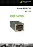
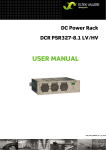
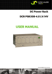
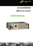
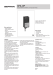
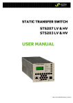
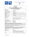
DC/AC INVERTER PWS Series USER MANUAL UM_PWS_E_R1.2 DC/AC Inverter PWS series User Manual Page 2 (24) Notes to this manual ATTENTION! Read this manual carefully before installing and commissioning the module. This manual is a part of the delivered module. Familiarity with the contents of this manual is required for installing and operating the module. The rules for prevention of accidents for the specific country and the general safety rules in accordance with IEC 364 must be observed. The function description in this manual corresponds to the date of publishing. Technical changes and changes in form and content can be made at any time by the manufacturer without notice. There are no obligations to update the manual continually. The module is manufactured in accordance with applicable DIN and VDE standards such as VDE 0106 (part 100) and VDE 0100 (part 410). The CE marking on the module confirms compliance with EU standards 2006-95-EG (low voltage) and 2004-108-EG (electromagnetic compatibility) if the installation and operation instructions are followed. Supplier: FAX Email Internet ELTEK VALERE DEUTSCHLAND GmbH GB Industrial Schillerstraße 16 D-32052 Herford + 49 (0) 5221 1708-210 + 49 (0) 5221 1708-222 [email protected] http://www.eltekvalere.com 2009. ELTEK VALERE DEUTSCHLAND GmbH. All rights reserved. ELTEK VALERE DEUTSCHLAND ©2009 UM_PWS_E_R1.2 DC/AC Inverter PWS series User Manual Page 3 (24) The current revision status of this user manual is the following: Revision: 1.2 Date: 2009-03-18 Revision 00 1.1 1.2 Description of change Former version “PWS_E1_neutral_20070416.doc” comprehensively reworked Minor text modifications and the new revision status numbering (X.X) inserted. Up-to-date photos inserted ELTEK VALERE DEUTSCHLAND ©2009 Writer Date RTH 2008-09-17 RTH 2008-10-29 RTH 2009-03-18 UM_PWS_E_R1.2 DC/AC Inverter PWS series User Manual Page 4 (24) Table of contents 1A. SAFETY INSTRUCTIONS .............................................................................................................5 1B. ELECTRIC WASTE DISPOSAL......................................................................................................5 2. GENERAL INFORMATION ...............................................................................................................6 2.1 Typical applications................................................................................................................................6 2.2 Type list .....................................................................................................................................................7 2.3 Available options.....................................................................................................................................7 2.4 Front view, operating and indicator elements.................................................................................8 2.5 Electrical connectors .............................................................................................................................9 2.5.1 Electrical connectors PWS-F ..........................................................................................................................9 2.5.2 Electrical connectors PWS-W ...................................................................................................................... 11 2.6 Cooling and air flow direction............................................................................................................ 12 3. HANDLING ..................................................................................................................................... 13 3.1 Storage ................................................................................................................................................... 13 3.2 Commissioning...................................................................................................................................... 13 3.2.1 Single inverter................................................................................................................................................. 14 3.2.2 Operation in parallel....................................................................................................................................... 14 3.3 LED indications...................................................................................................................................... 15 3.4 Monitoring .............................................................................................................................................. 16 3.5 Potentiometer....................................................................................................................................... 16 3.6 Rear-side switch S2 (remote switch-on function) ....................................................................... 17 4. MAINTENANCE ............................................................................................................................. 18 5. TROUBLE SHOOTING................................................................................................................... 18 6 TECHNICAL SPECIFICATIONS ..................................................................................................... 19 6.1 General technical specifications ...................................................................................................... 19 6.2 Specific data.......................................................................................................................................... 20 6.3 Dimensional drawings PWS-F ............................................................................................................ 21 6.4 Dimensional drawings PWS-W........................................................................................................... 21 7. NOTES ............................................................................................................................................ 22 Index of figures Figure 1) - PWS-F in parallel operation...........................................................................................................................6 Figure 2) - PWS-F in parallel operation with static bypass switch .........................................................................6 Figure 3) - Front view PWS-F ............................................................................................................................................8 Figure 4) - PWS-F male connectors ................................................................................................................................9 Figure 5) - Screw terminals PWS-W............................................................................................................................. 11 Figure 6a) - Module air flow, PWS-F ............................................................................................................................. 12 Figure 6b) - Module air flow, PWS-W ........................................................................................................................... 12 Figure 7) - Mounting set for PWS-F.............................................................................................................................. 13 Figure 8) - Potentiometer and testjack...................................................................................................................... 16 Figure 9) - Detail: Rear side switch S2 ........................................................................................................................ 17 Figure 10) - PWS-F dimensions ..................................................................................................................................... 21 Figure 11) - PWS-W dimensions.................................................................................................................................... 21 ELTEK VALERE DEUTSCHLAND ©2009 UM_PWS_E_R1.2 DC/AC Inverter PWS series User Manual Page 5 (24) 1A. Safety Instructions Warning! Because several components of operating electrical modules are charged by dangerous voltage, the improper handling of electrical modules may be the cause of accidents involving electrocution, injury, or material damages. Operation and maintenance of electrical modules must be performed by qualified skilled personnel such as electricians in accordance with EN 50110-1 or IEC 60950. Install the module only in areas with limited access to unskilled personnel. Before starting work, the electrical module must be disconnected from mains. Make sure that the module is earthed. Do not touch connector pins as they can be charged with dangerous voltage up to 30 seconds after disconnection. Only spare parts approved by the manufacturer must be used. 1B. Electric Waste Disposal Separate collection is the precondition to ensure specific treatment and recycling of waste electrical and electronic equipment and is necessary to achieve the chosen level of protection of human health and the environment. In the case of waste disposal of your discarded equipment we recommend to contact a waste management company. ELTEK VALERE DEUTSCHLAND ©2009 UM_PWS_E_R1.2 DC/AC Inverter PWS series User Manual Page 6 (24) 2. General information The PWS inverter family (1kVA–5kVA, 24V version max. 2.5kVA) is equipped with a 50Hz isolation transformer following a primary side pulse-width modulation stage and is available as 19”-compatible rack (PWS-F) or wall mounted cabinet (PWS-W). PWS inverters are especially suited for applications in power plants, industrial, railroad and shipping AC power supplies. The combination of rugged mechanical construction, high overload ability and electrical isolation between input and output offers a very high flexibility in system configuration. The inverters can be operated as single unit or in parallel connection (as option) to provide power increase or further improved reliability by (n+1)-redundancy. The operation in combination with a static bypass switch (UNB) is also possible. The PWS-F is fitted with a rear side connector, the PWS-W is fitted with screw terminals at the bottom. All operation and indication elements are arranged at the front side. The wall cabinet version includes all necessary input and output fuses and can be directly mounted beside the load distribution. Optionally, versions with an included static bypass switch, special output voltages, special output frequency or further special models are available on request. 2.1 Typical applications Figure 1) - PWS-F in parallel operation ELTEK VALERE DEUTSCHLAND ©2009 Figure 2) - PWS-F in parallel operation with static bypass switch UNB UM_PWS_E_R1.2 DC/AC Inverter PWS series User Manual Page 7 (24) 2.2 Type list PWS-F (19’’ version) Type designation Article code PWS24-1.0F PWS110-1.0F PWS220-1.0F 401-010-411.00 401-010-711.00 401-010-811.00 Input voltage (VDC) 24 108 216 PWS24-2.5F PWS110-2.5F PWS220-2.5F 401-025-411.00 401-025-711.00 401-025-811.00 PWS110-5.0F PWS220-5.0F 401-050-711.00 401-050-811.00 Output voltage (VAC) Output power (kVA @ cos phi 0.8) 230 1.0 24 108 216 230 2.5 108 216 230 5.0 PWS-W (wall cabinet version) Type designation Article code PWS24-1.0W PWS110-1.0W PWS220-1.0W 401-010-412.00 401-010-712.00 401-010-812.00 Input voltage (VDC) 24 108 216 PWS24-2.5W PWS110-2.5W PWS220-2.5W 401-025-412.00 401-025-712.00 401-025-812.00 PWS110-5.0W PWS220-5.0W 401-050-712.00 401-050-812.00 Output voltage (VAC) Output power (kVA @ cos phi 0.8) 230 1.0 24 108 216 230 2.5 108 216 230 5.0 2.3 Available options Article designation Parallel operation choke Mounting set Internal static transfer switch Extended AC distribution board ELTEK VALERE DEUTSCHLAND ©2009 Article code 402-POC-012.00 402-POC-033.00 402-POC-050.00 880-MEC-MKT.03 Suitable for: PWS-1.0F PWS-2.5F PWS-5.0F PWS-F versions Several types, depending on the used PWS PWS-F and PWS wall cabinet versions UM_PWS_E_R1.2 DC/AC Inverter PWS series User Manual Page 8 (24) 2.4 Front view, operating and indicator elements Ammeter (Iout) Handle Voltmeter (Vout) Cooling-air intake ON/OFF switch S1 LED display with potentiometer and testjack Figure 3) - Front view PWS-F The PWS is equipped with the following seven LED indicators: o o o o o o o OPERATION Vout Vin> Vin< ERROR OVERLOAD/TEMP.> COLL. FAILURE At the bottom of the LED indicators a potentiometer in combination with a testjack is placed. With the potentiometer the AC output voltage can be fine adjusted while the voltage value can be measured at the testjack. The voltmeter indicates the AC output voltage, the ammeter indicates the AC output current. With the switch S1 the inverter can be switched ON /OFF. NOTE: For more information about the indicator and operating elements read the following sections. ELTEK VALERE DEUTSCHLAND ©2009 UM_PWS_E_R1.2 DC/AC Inverter PWS series User Manual Page 9 (24) 2.5 Electrical connectors 2.5.1 Electrical connectors PWS-F The rear side male connections (DC input voltage, AC output voltage and signals) are shown in figure 4) and are defined in the table below. PE 1 3 2 4 9 5 12 8 PE Figure 4) - PWS-F male connectors (shown from the rear side of the module) Pin assignment of the rear side connector (except for PWS24-2.5F): Pin 1 2 3 4 5 6 7 8 9 10 Function L+ (DC-INPUT) N (NEUTRAL) L- (DC-INPUT) L1 (Phase L) not used SYNC-GND 1) synchronization ground for paralleling SYNC-SIG 1) synchronization bus for paralleling SYNC-STAT 2) control wire from static bypass switch Remote switch on coll. failure: COM* 11 coll. failure: NO* 12 coll. failure: NC* * No collective failure is existent: COM and NO are closed. * Collective failure is existent: COM and NC are closed. 1) If Inverters are connected in parallel, interconnect all SYNC-GND (pins 6) with each other and interconnect all SYNC-SIG (pins 7) with each other. 2) If the inverters operate in combination with a static bypass switch UNB, it is also necessary, to interconnect all SYNC-STAT (pins 8) with each other, including SYNC-STAT of the UNB. ELTEK VALERE DEUTSCHLAND ©2009 UM_PWS_E_R1.2 DC/AC Inverter PWS series User Manual Page 10 (24) REMARK: The pinning of the PWS24-2.5F is different due to the higher input current flow! Pin assignment of the rear side connector for PWS24-2.5F: Pin 1 2 3 4 5 6 7 8 9 10 Function L+ (DC-INPUT) L+ (DC-INPUT) L- (DC-INPUT) L- (DC-INPUT) L1 (Phase L) SYNC-GND 1) synchronization ground for paralleling SYNC-SIG 1) synchronization bus for paralleling 2) SYNC-STAT control wire from static bypass switch N (NEUTRAL) 11 coll. failure: NO* Remote switch on 12 coll. failure: COM* * No collective failure is existent: COM and NO are closed. * Collective failure is existent: COM and NO are open. 1) If Inverters are connected in parallel, interconnect all SYNC-GND (pins 6) with each other and interconnect all SYNC-SIG (pins 7) with each other. 2) If the inverters operate in combination with a static bypass switch UNB, it is also necessary, to interconnect all SYNC-STAT (pins 8) with each other, including SYNC-STAT of the UNB. ELTEK VALERE DEUTSCHLAND ©2009 UM_PWS_E_R1.2 DC/AC Inverter PWS series User Manual Page 11 (24) 2.5.2 Electrical connectors PWS-W The electrical connectors (screw terminals, see Figure 5) for a sample) are located at the bottom of the module. They are accessible after opening the front door. The wires are to be inserted through the grommets at the bottom and connected to the screw terminals according to the following table. Figure 5) - Screw terminals PWS-W Figure 5) shows a sample. The genuine screw terminals may look a little bit different depending on the PWS type. Terminal/designation X1 + - Function DC input + - X2 1 2 PE AC output L N PE X3 1 Signals 2 coll. failure: NO* 3 coll. failure: NC* SYNC-GND SYNC-SIG SYNC-STAT 4 5 6 coll. failure: COM* * No collective failure is existent: COM and NO are closed. * Collective failure is existent: COM and NC are closed. ELTEK VALERE DEUTSCHLAND ©2009 UM_PWS_E_R1.2 DC/AC Inverter PWS series User Manual Page 12 (24) 2.6 Cooling and air flow direction The PWS units are cooled with an internal fan. The airflow is from the front to rear side (PWS-F version), from bottom to top (PWS wall cabinet version). The fan is monitored and speed-controlled dependent on module temperature. To provide sufficient air flow, a minimum space (see figure 6a), item “A”) of 50 mm is required between the rear panel of the module and the rear cabinet wall as well as an unobstructed supply of air to the front of the module. For PWS-W a minimum space of 2U (approx. 90mm) above the top of the module (see figure 6b), item “A”) is recommended. Figure 6a) - Module air flow, PWS-F ELTEK VALERE DEUTSCHLAND ©2009 Figure 6b) - Module air flow, PWS-W UM_PWS_E_R1.2 DC/AC Inverter PWS series User Manual Page 13 (24) 3. Handling 3.1 Storage The modules must be stored in a dry, dust free environment with a storage temperature in accordance with the technical specifications (see section 6). 3.2 Commissioning Note: Before commissioning the module make sure that the input voltage level corresponds to the nominal input voltage of the unit according to the type plate. To mount the inverter in a 19’’ compatible cabinet, a mounting set is necessary (see figure 7). After unpacking the unit put it upon the rails and slide in the unit carefully over the rails until the module connector gets in touch with the backplane connector. Increase the pressure a little bit until the unit fits in completely. Please avoid too much pressure. If the unit does not fit in please start again with the complete slide-in process. Mount the unit with 4 screws (M4x12). Figure 7) - Mounting set for PWS-F (the picture shows not a PWS but a similar module) For the connection of DC input and AC output the PWS-F is fitted with a backside panel connector (the PWS-W is fitted with screw terminals at the bottom). The DC input is protected against incorrect polarity (if the polarity is reversed, the unit does not switch on). The PWS-W serially is equipped with an internal input and output fuse (see section 6.2 “Specific data”). The PWS-F has no internal fuses. Therefore the module is to be fused with external fuses according to section 6.2 “Specific data”. Check the load current before connecting the module. A permanent overload is not allowed and decreases the inverters lifetime. Especially the inrush currents of consumer loads have to be observed (e.g. the inrush current of a common used computer monitor can be more than 50 A!). For the safety of individuals, the connection of a non-fused protective earth conductor generally is required. Due to the specific overload and short circuit behaviour of the PWS, additional safety measures are to be arranged at the output (e. g. ground fault circuit interrupter). ELTEK VALERE DEUTSCHLAND ©2009 UM_PWS_E_R1.2 DC/AC Inverter PWS series User Manual Page 14 (24) Connect the input, output and signalling wires according to section 2.5 “Electrical connectors”. Wires in accordance with VDE 0100 or equal standard are to be used. To decrease voltage losses on cables the usage of larger wire cross sections as specified is recommended. For instance, a high voltage loss on battery wires can decrease the backup time. Following installation rules should be observed: 3.2.1 Single inverter 1. 2. 3. 4. 5. 6. 7. check the system wiring ( polarity of DC- supply line ) check that the inverter is switched off connect DC input with open DC busbar fuses connect AC loads close the DC busbar fuses switch on the unit with front side switch S1. The rear side switch S2* must be in position “I”. switch on the load * REMARK: For more information about switch S2, see section 3.6. 3.2.2 Operation in parallel REMARK: For parallel operation of PWS inverters it is necessary to use parallel operation chokes at the outputs of the inverters as shown in figure 1+2). The article codes of the parallel operation chokes are listed in section 2.3 “Available options”. 1. 2. 3. 4. 5. 6. 7. 8. make shure that the inverters to be paralleled are identical in type. check the system wiring (polarity of DC- supply line, synchronous bus) check that the inverters are switched off connect DC input with open DC busbar fuses check the wiring between the inverters (synchronization wires) connect AC loads close DC busbar fuses switch on the units with front side switches (rear side switch S2 in position “0” for remote switchon function in combination with a static bypass switch UNB). 9. switch on the load One of the paralleled inverters operates as master and synchronizes the other inverters to a given frequency. Note: The unit which first of all feeds in is the master. If the master unit fails or is switched off, another unit overtakes the master function. If paralleled inverters operate in combination with a static bypass switch (UNB), the UNB automatically is the master. The connected inverters are synchronized by the UNB via the control wire SYNC-STAT. For a faultless function it is important that the wiring between the inverters (and static bypass switch) is correct. The inverters connect themselves to the AC output (over an internal output-side contactor) not till then the output voltage reaches the nominal value. REMARK: Due to the connected parallel operation chokes in combination with the resistance of the wiring the short circuit detection of the units will be affected. For this application, it is recommended to check individually the short circuit behavior of the system. Due to the voltage losses at the inductance of the parallel operation choke, the voltage deviation value exceeds the specified data of the data sheet of the PWS. ELTEK VALERE DEUTSCHLAND ©2009 UM_PWS_E_R1.2 DC/AC Inverter PWS series User Manual Page 15 (24) 3.3 LED indications The following functions are indicated with front side LED indicators: LED Colour Designation Meaning green OPERATION Inverter is switched ON, internal supply voltage available green Vout Inverter output voltage available red Vin> Input overvoltage; inverter switched OFF red Vin< Input undervoltage; inverter switched OFF red Error Output voltage distorted due to short circuit or overload at the output red OVERLOAD/ TEMP. Overheating of the inverter /continuous overload. red COLL. FAILURE Collective failure: The delay time is 20s; the relay contact* reacts at the same time. The following failures are combined: Vin<, Vin>, ERROR, OVERLOAD/TEMP. * Maximum contact load: Vmax. 110VDC/Imax. <0.45ADC Vmax. 60VDC/Imax. <1ADC Vmax. 24VDC/Imax. <8ADC ELTEK VALERE DEUTSCHLAND ©2009 UM_PWS_E_R1.2 DC/AC Inverter PWS series User Manual Page 16 (24) 3.4 Monitoring Monitored values Criteria Input voltage <85% (±2%) Vi nom. DC input voltage Input voltage >128% (±2%) Vi nom. AC output voltage Overload/temperature* Output voltage <90% Vout nom. Heat sink temperature of the power amplifier of the inverter >90°C. Function LED “Vi<” = ON. The module automatically undelayed switches off. It automatically switches on when the input voltage reaches 103% (±2%) Vi nom. The hysteresis prevents oscillating of the automatic switch-off. LED “Vi>” = ON. The module automatically undelayed switches off (overvoltage protection). It automatically switches on when the input voltage decreases to 125% (±2%) Vi nom. LED “ERROR” = ON. The module automatically switches off, time delay = 2.5s. An automatic restart with progressive run-up follows after 15s. Due to this the module is continuous short circuit proof. LED “OVERLOAD/TEMP.>” = ON. The module automatically switches off if the temperature does not decrease. It automatically switches on when the heat sink cools down to ≤70°C. * Possible reasons: Elevated ambient temperature, continuous overload (approx. 20-25%) or a defective fan. Overload capability: See section 6 “Technical specification”. REMARK: Keep the maximum allowed overload time because the module does not automatically switch off. 3.5 Potentiometer Below the LED indicators the PWS-F is fitted with a potentiometer for fine adjustment of the AC output voltage. Potentiometer Testjack With the potentiometer the AC output voltage can be fine adjusted (e.g. for the compensation of voltage losses at the parallel operation choke). Adjustment range: ±2VAC. The output voltage can be measured at the testjack. Ratio= 1:100 (1V =100V). But it is recommended to measure the output voltage at the output of the module with consideration of possible voltage losses at the internal wiring and parallel operation choke. Figure 8) - Potentiometer and testjack ELTEK VALERE DEUTSCHLAND ©2009 UM_PWS_E_R1.2 DC/AC Inverter PWS series User Manual Page 17 (24) 3.6 Rear-side switch S2 (remote switch-on function) The remote switch-on function is designed to switch on/off all paralleled PWS-F inverters simultaneously. For this function the DC input voltage monitoring function of the static bypass switch UNB is used. If the UNB detects “DC input voltage is okay” the signal for remote switch-on is sent via the wire connected to pin 9 (pin 12 respectively) of the PWS connector. In reverse: If the DC input voltage is not okay, the remote switch-off signal is sent. With switch S2 (see figure 9)) fitted on the rear side of the PWS-F it is possible to enable/disable the remote switch-on function depending on the intended use. Figure 9) - Detail: Rear side switch S2 Switch 2 position “1”= remote switch-on function disabled. In this position, the module can be switched ON and OFF with the front side switch S1. Switch 2 position “O”= remote switch-on function enabled. In this position, the module can be remotely switched ON and OFF by the static bypass switch UNB. Table “Function of switch 1 and switch 2”: Switch position of S1 S2 Function 0 1 Module manually switched OFF, remote switch-on function disabled. 1 1 Module switched ON, remote switch-on function disabled (stand-alone mode) 0 0* Module manually switched OFF, remote switch-on function enabled. 1 0* Module switched ON, remote switch-on function enabled. * REMARK: When the PWS is used as stand alone module, it can not be switched ON with S1 if the position of S2 is “0”. For a faultless remote switch on function it is important that the wiring between the inverters and static bypass switch (remote switch on wire) is correct. INFO: The PWS-F series is serially fitted with the rear side switch since August 2008 (date of manufacture). ELTEK VALERE DEUTSCHLAND ©2009 UM_PWS_E_R1.2 DC/AC Inverter PWS series User Manual Page 18 (24) 4. Maintenance In general, the module is maintenance-free. A yearly inspection with following checks is recommended: Optical/mechanical inspection Fan function Removal of dust and dirt, especially on radiator surfaces Check for internal dust or humidity Attention! Dust combined with moisture or water may influence or destroy the internal electronic circuits. Dust inside the unit can be blown out with dry compressed air. The interval between the checks depends on ambient conditions of the installed module. 5. Trouble shooting Symptom No output voltage Possible reason DC input voltage ok? main switch (MCB) on? green LED „OPERATION“ on? Incorrect polarity at the input? DC input fuse (at DC busbar) ok? signalling LED “Vin>” or “Vin<” on ? Corrective action → check → check → check → check → check → check short circuit or overload at the output? output fuse ok? Unit switched off due to overheating (LED “OVERLOAD/TEMP.>” on)? → check/reduce load → check → search for the cause of the overheating overload at the output? Is the voltage adjustment (potentiometer) correct? → check/reduce load → check/adjust Deviation of the output voltage If the unit still does not work even though all checks are done, please contact your sales agent or the Eltek Valere Deutschland service department. ELTEK VALERE DEUTSCHLAND ©2009 UM_PWS_E_R1.2 DC/AC Inverter PWS series User Manual Page 19 (24) 6 Technical specifications 6.1 General technical specifications Input: Input voltage according to the type list (see section 2.2) Input voltage range +20%/-15% Vnom Input current according to the table “specific data” (see section 6.2) Inrush current ≤nominal input current Output: Output power factor range 0 inductive – 1 – 0 capacitive Output voltage 230VAC ±0.5%*; sinusoidal Output power according to the type list (see section 2.2) Output frequency 50Hz ±0.05% THD ≤3% at linear load Efficiency 85 – 91% (depending on the type, see section 6.2) Crest factor ≤2.5 ≤3% at load variations of 10% - 100% - 10% Inom (transient time Dynamic behaviour* ≤1.5ms) * PWS modules in parallel operation: Due to the external parallel operation chokes to be used, the static and dynamic output voltage deviation increases to the following values: static= ±5%; dynamic= ±10%. Short circuit protection Monitoring: DC input voltage AC output voltage Overload capability LED indicators Relay contact Parallel operation External synchronization Analogue measurement instruments Environmental: continuous short circuit proof; 2 - 2.5 Inom for approx. 2.5s. Vin<; Vin> (with switch-off and automatic switch-on) Vout; overtemperature (with switch-off); overload (without switch-off) 160% for 1 min./130% for 10 min. (without switch-off) OPERATION, Vout, Vin<, Vin>, ERROR, OVERLOAD/TEMP., COLL. FAILURE Collective failure; maximum contact load: Vmax. 110VDC/Imax. <0.45ADC Vmax. 60VDC/Imax. <1ADC Vmax. 24VDC/Imax. <8ADC max. 12 modules with external parallel operation choke, load sharing approx. 5%, yes Vout, Iout Ambient temperature Operation: -20°C to +55°C, storage: -40°C to +85°C Climatic conditions according to IEC 721-3-3 class 3K3/3Z1/3B1/3C2/3S2/3M2 ELTEK VALERE DEUTSCHLAND ©2009 UM_PWS_E_R1.2 DC/AC Inverter PWS series User Manual Page 20 (24) Max. installation altitude Noise emission ≤ 1500m <45dBA Mechanical: Type of construction Cooling 19’’ compatible casing or wall cabinet (depending on the type) Fan cooling (temperature regulated and monitored) Dimensions/weight according to the table “specific data” (see section 6.2) Surfaces Front panel (PWS-F) and wall cabinet: powder-coated, RAL7035 Compliances: Type of enclosure/ protection class CE conformity Compliance to safety standards Compliance to EMC standards Mechanical: IP20; electrical: according to EN60950-1 Yes EN60950-1; VDE0100 T410; VDE0110; EN50178; EN60146 EN 55011; EN 55022 class “B”; EN 61000-4, part 2-5 6.2 Specific data Input voltage Output power Effi(VDC) (kVA @ cos phi ciency = 0.8) (%) Input current (ADC) Output current (AAC) Input/ output Weight 19’’ rack/ fuses* (A) wall cabinet (kg) approx. 50/6 20/24 24 1.0 85 38.8 4.35 108 1.0 90 8.2 4.35 10/6 216 1.0 90 4.1 4.35 24 2.5 86 96.9 108 2.5 91 216 2.5 108 216 Dimensions 19“ rack Dimensions wall cabinet E1 C2 19/23 E1 C2 6/6 19/23 E1 C2 10.9 125/16 34/42 E2 C4 20.4 10.9 25/16 34/42 E1 C2 91 10.2 10.9 16/16 34/42 E1 C2 5.0 91 39.9 21.7 50/25 52/64 E2 C5 5.0 91 20.0 21.7 25/25 52/64 E2 C5 * The PWS-W is serially fitted with internal input and output fuses. The PWS-F has no internal fuses. It is recommended to use external fuses according to the table above. ELTEK VALERE DEUTSCHLAND ©2009 UM_PWS_E_R1.2 DC/AC Inverter PWS series User Manual Page 21 (24) 6.3 Dimensional drawings PWS-F PWS-F A (mm) B (mm) E1 177 (4U) 101.7 E2 221 (5U) 146.1 Figure 10) - PWS-F dimensions 6.4 Dimensional drawings PWS-W Figure 11) - PWS-W dimensions PWS-W A (mm) B (mm) C (mm) D (mm) E (mm) C2 600 666 365 400 210 C4 600 666 565 600 300 C5 800 866 565 600 300 The dimensions of the slotted holes of the wall holder mountings are 8.5 x 12.5mm. ELTEK VALERE DEUTSCHLAND ©2009 UM_PWS_E_R1.2 DC/AC Inverter PWS series User Manual Page 22 (24) 7. Notes ELTEK VALERE DEUTSCHLAND ©2009 UM_PWS_E_R1.2 DC/AC Inverter PWS series User Manual Page 23 (24) Notes ELTEK VALERE DEUTSCHLAND ©2009 UM_PWS_E_R1.2 Supplier: FAX Email Internet ELTEK VALERE DEUTSCHLAND GmbH GB Industrial Schillerstraße 16 D-32052 Herford + 49 (0) 5221 1708-210 + 49 (0) 5221 1708-222 [email protected] http://www.eltekvalere.com 2009. ELTEK VALERE DEUTSCHLAND GmbH. All rights reserved.