1
This manual not printed
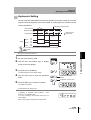
Smart Electrostatic Sensor
ZJ-SD Series
User's Manual
Cat. No. Z237-E1-03
Introduction
Thank you for purchasing the ZJ-SD.
This manual provides information regarding functions, performance and operating methods that
are required for using the ZJ-SD.
When using the ZJ-SD, be sure to observe the following:
• The ZJ-SD must be operated by personnel knowledgeable in electrical engineering.
• To ensure correct use, please read this manual thoroughly to deepen your understanding of the
product.
• Please keep this manual in a safe place so that it can be referred to whenever necessary.
Section 1 FEATURES
Section 2 PREPARATION FOR MEASUREMENT
Section 3 BASIC OPERATION
Section 4 MAIN APPLICATIONS AND SETTING METHODS
Section 5 DETAILED SETTINGS
Section 6 AUXILIARY FUNCTIONS
Section 7 APPENDICES
User’s Manual
Smart Electrostatic Sensor
ZJ-SD Series
Introduction Section 1 Section 2 Section 3 Section 4 Section 5 Section 6 Section 7
Introduction APPLICATION CONSIDERATIONS (Please Read)
Introduction
Terms and Conditions Agreement
Introduction
Terms and Conditions Agreement
Warranty, Limitations of Liability
WARRANTY
Exclusive Warranty
Omron’s exclusive warranty is that the Products will be free from defects in materials and workmanship
for a period of twelve months from the date of sale by Omron (or such other period expressed in writing
by Omron). Omron disclaims all other warranties, express or implied.
Limitations
OMRON MAKES NO WARRANTY OR REPRESENTATION, EXPRESS OR IMPLIED, ABOUT NONINFRINGEMENT, MERCHANTABILITY OR FITNESS FOR A PARTICULAR PURPOSE OF THE
PRODUCTS. BUYER ACKNOWLEDGES THAT IT ALONE HAS DETERMINED THAT THE PRODUCTS
WILL SUITABLY MEET THE REQUIREMENTS OF THEIR INTENDED USE.
Omron further disclaims all warranties and responsibility of any type for claims or expenses based on
infringement by the Products or otherwise of any intellectual property right.
Buyer Remedy
Omron’s sole obligation hereunder shall be, at Omron’s election, to (i) replace (in the form originally
shipped with Buyer responsible for labor charges for removal or replacement thereof) the non-complying
Product, (ii) repair the non-complying Product, or (iii) repay or credit Buyer an amount equal to the
purchase price of the non-complying Product; provided that in no event shall Omron be responsible for
warranty, repair, indemnity or any other claims or expenses regarding the Products unless Omron’s
analysis confirms that the Products were properly handled, stored, installed and maintained and not
subject to contamination, abuse, misuse or inappropriate modification. Return of any Products by Buyer
must be approved in writing by Omron before shipment. Omron Companies shall not be liable for the
suitability or unsuitability or the results from the use of Products in combination with any electrical or
electronic components, circuits, system assemblies or any other materials or substances or
environments. Any advice, recommendations or information given orally or in writing, are not to be
construed as an amendment or addition to the above warranty.
See http://www.omron.com/global/ or contact your Omron representative for published information.
Limitation on Liability; Etc
OMRON COMPANIES SHALL NOT BE LIABLE FOR SPECIAL, INDIRECT, INCIDENTAL, OR
CONSEQUENTIAL DAMAGES, LOSS OF PROFITS OR PRODUCTION OR COMMERCIAL LOSS IN
ANY WAY CONNECTED WITH THE PRODUCTS, WHETHER SUCH CLAIM IS BASED IN CONTRACT,
WARRANTY, NEGLIGENCE OR STRICT LIABILITY.
Further, in no event shall liability of Omron Companies exceed the individual price of the Product on
which liability is asserted.
ii
ZJ-SD
User’s Manual
Introduction
Terms and Conditions Agreement
Introduction
Application Considerations
Suitability of Use
Omron Companies shall not be responsible for conformity with any standards, codes or regulations
which apply to the combination of the Product in the Buyer’s application or use of the Product. At Buyer’s
request, Omron will provide applicable third party certification documents identifying ratings and
limitations of use which apply to the Product. This information by itself is not sufficient for a complete
determination of the suitability of the Product in combination with the end product, machine, system, or
other application or use. Buyer shall be solely responsible for determining appropriateness of the
particular Product with respect to Buyer’s application, product or system. Buyer shall take application
responsibility in all cases.
NEVER USE THE PRODUCT FOR AN APPLICATION INVOLVING SERIOUS RISK TO LIFE OR
PROPERTY WITHOUT ENSURING THAT THE SYSTEM AS A WHOLE HAS BEEN DESIGNED TO
ADDRESS THE RISKS, AND THAT THE OMRON PRODUCT(S) IS PROPERLY RATED AND
INSTALLED FOR THE INTENDED USE WITHIN THE OVERALL EQUIPMENT OR SYSTEM.
Programmable Products
Omron Companies shall not be responsible for the user’s programming of a programmable Product, or
any consequence thereof.
Disclaimers
Performance Data
Data presented in Omron Company websites, catalogs and other materials is provided as a guide for the
user in determining suitability and does not constitute a warranty. It may represent the result of Omron’s
test conditions, and the user must correlate it to actual application requirements. Actual performance is
subject to the Omron’s Warranty and Limitations of Liability.
Change in Specifications
Product specifications and accessories may be changed at any time based on improvements and other
reasons. It is our practice to change part numbers when published ratings or features are changed, or
when significant construction changes are made. However, some specifications of the Product may be
changed without any notice. When in doubt, special part numbers may be assigned to fix or establish key
specifications for your application. Please consult with your Omron’s representative at any time to
confirm actual specifications of purchased Product.
Errors and Omissions
Information presented by Omron Companies has been checked and is believed to be accurate; however,
no responsibility is assumed for clerical, typographical or proofreading errors or omissions.
ZJ-SD
User’s Manual
iii
Introduction
Precautions for Safe Use
Introduction
Precautions for Safe Use
The following points are important to ensure safety, so make sure that they are strictly observed.
Installation Environment
•
Do not use the product in environments where it can be exposed to inflammable/
explosive gas.
•
Do not install the product close to high-voltage devices and power devices in order to
secure the safety of operation and maintenance.
Power Supply and Wiring
•
The supply voltage must be within the rated range.
•
Open-collector outputs should not be short-circuited.
•
High-voltage lines and power lines must be wired separately from this product. Wiring
them together or placing them in the same duct may cause induction, resulting in
malfunction or damage.
•
Avoid connecting or disconnecting connectors while the product is powered ON.
Doing so may damage the product.
•
Reverse connection of the power supply and output terminals is not allowed.
Connection to an AC power supply is also not allowed.
•
Connect a supply voltage and current within the rated ranges to the output terminals.
Others
•
Do not disassemble, repair, or modify this product.
•
This product is not compatible with the ZX series. Do not connect a ZJ-S___ in
combination with a ZX series Amplifier Unit.
•
Supply power from a UL Class 2 DC power supply or a DC power supply unit that has
a countermeasure (safety ultra-low voltage circuit) built-in for preventing high voltages
from occurring.
•
Be sure to insulate the sensor case as it is connected to the 0 V line of the internal
circuits.
•
Always ground the 0 V terminal to prevent electrical shock and to enable performing
measurements correctly.
•
Do not operate this product with wet hands. Doing so might cause a malfunction.
•
Do not ground the 24 V terminal. Doing so may cause malfunctions.
•
Do not drop this product or subject it to strong shock. Doing so might cause a
malfunction.
•
Prevent static discharge from being applied to the Sensor Head even if it is operating
within the measurement voltage range. Doing so might cause a malfunction.
•
iv
ZJ-SD
Dispose of this product as industrial waste.
User’s Manual
Introduction
Precautions for Correct Use
Observe the following precautions to prevent failure to operate, malfunctions, or undesirable effects on
product performance.
Introduction
Precautions for Correct Use
Installation Site
Do not install the product in locations subjected to the following conditions:
• Ambient temperature outside the rating
•
Rapid temperature fluctuations (causing condensation)
•
Relative humidity outside the rating
•
Presence of corrosive or flammable gases
•
Presence of dust, salt, or iron particles
•
Direct vibration or shock
•
Direct sunlight
•
Water, oil, or chemical fumes or spray
•
Strong magnetic or electric field
Component Installation and Handling
Power Supply and Wiring
•
The cables must be 10 m or shorter in total length, for both the sensor and Amplifier
Unit. To extend the cable from the Sensor Head, an optional double-ended connector
cable (ZX-XC_A) must be used. For extension of the cable of Amplifier Units, shielded
cables of the same type must be used.
•
When using a commercially available switching regulator, make sure that the FG
(Frame Ground) terminal is grounded.
•
If surge currents are present in the power lines, connect surge absorbers that suit the
operating environment.
•
When two or more Amplifier Units are connected by a Calculating unit (ZX-CAL2) for
use, connect the linear GND of all Amplifier Units.
Warming Up
After turning ON the power supply, allow the product to stand for at least 30 minutes
before use. The circuits are still unstable just after the power supply is turned ON, so
measured values may fluctuate gradually.
Maintenance and Inspection
•
Always turn OFF the power supply before adjusting or connecting/disconnecting the
Sensor Head.
•
Do not use thinner, benzene, acetone or kerosene to clean the Sensor Head and
Amplifier Units.
•
Do not allow dust to enter the measurement section.
ZJ-SD
User’s Manual
v
Introduction
Editor's Note
Introduction
Editor's Note
Page Format
zTitle of each section
zHeader
Indicates the contents of the page.
Section 5
Using the Hold Functions
zOverview
Using the Hold Functions
The "hold functions" hold data for specific points during the measurement period, such as the
Describes the overview and
operation flow of the section.
minimum and maximum values, and output those values after measurement ends.
• Flow of Operation
1
2
3 (if required)
Selecting the Hold
Setting the Trigger
Set the Trigger
Condition for
for Measurement in
Direction and
Measured Values
the Hold Mode
Self-trigger Level
4 (if required)
zCross-header
Setting the Delay
Time
zOverview and points of
the function described
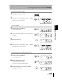
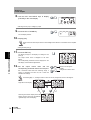
Selecting the Hold Condition for Measured Values
After sampling is started, the CLAMP value is output until the first sampling period ends.
What is the "CLAMP value?" p.73
Moving to the FUN mode and HOLD
1. Set the mode switch to FUN.
2. Use the LEFT and RIGHT keys to display
[HOLD] on the main display.
Section 5 DETAILED SETTINGS
The time period from the start to the end of hold measurements is called the "sampling
period."
The value to be held during that sampling period is selected here.
zIndex label
Shows the chapter number
and contents.
zPurpose of operation
Shows the contents of the
operation to be performed.
Selecting the hold condition
3. Press the UP or DOWN key.
The sub-display flashes.
4. Use the UP and DOWN keys to select the
desired hold condition.
5. Press the ENT key to confirm the setting.
This registers the setting.
ZJ-SD
User's Manual
53
zDisplay
Shows the display status resulting from the operation.
zKeys or switches to be used
Illustrates the keys and switches to be used.
zOperation procedure and supplementary explanation
Explains the operation procedure and the display
status resulting from execution of the operation.
Helpful information regarding operation and
reference pages is introduced here using symbols.
* This page does not exist.
vi
ZJ-SD
User’s Manual
Introduction
Editor's Note
Introduction
Notational Conventions
Menu
In this manual, menu items displayed on the screen are enclosed with [ ].
Operation procedure
Operation steps are numbered to indicate their order.
Visual Aids
Indicates points that are important to achieve the full product performance, such as operational
precautions and application procedures.
Indicates pages where related information can be found.
Indicates information helpful in operation.
ZJ-SD
User’s Manual
vii
Introduction
CONTENTS
Introduction CONTENTS
CONTENTS
Terms and Conditions Agreement
ii
Precautions for Safe Use
iv
Precautions for Correct Use
v
Editor's Note
vi
CONTENTS
viii
Section 1 FEATURES
1
ZJ-SD Features
2
Section 2 PREPARATION FOR MEASUREMENT
viii
5
Basic Configuration
6
Part Names and Functions
9
Installing the Amplifier Unit
13
Installing Sensor Heads
15
Mounting on the Mounting Bracket
17
Connections
19
Wiring Input/Output Cables
23
ZJ-SD
User’s Manual
Introduction
CONTENTS
25
Flow of Operation
26
Basic Knowledge for Operation
28
Function Transition Charts
33
Correcting the Measurement Reference Voltage
36
Selecting the Measurement Mode
40
Setting the Installation Distance
41
Section 4 MAIN APPLICATIONS AND SETTING METHODS
Measuring Sheet Workpieces
Section 5 DETAILED SETTINGS
Introduction CONTENTS
Section 3 BASIC OPERATION
45
46
51
Setting the Number of Samples to Average
52
Using the Hold Functions
53
Entering Threshold Values
64
Linear Output
70
Setting Judgment Output Timing (Timer)
79
Setting the Warning Level (Output type)
82
Using the Area Correction Function
85
Selecting Banks
88
ZJ-SD
User’s Manual
ix
Introduction
CONTENTS
Introduction CONTENTS
Section 6 AUXILIARY FUNCTIONS
Changing the Number of Display Digits
92
Reversing the Display
93
Adjusting Display Brightness (ECO Display)
95
Key Lock Function
96
Initializing Setting Data
97
Changing Display Scales
99
Comparing Measured Values (Differentiation Function)
Section 7 APPENDICES
x
91
105
109
Troubleshooting
110
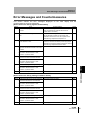
Error Messages and Countermeasures
111
Q&A
113
Glossary
114
Specifications and Dimensions
115
Communicating with the Static Electricity Smart Monitor via the Interface Unit
124
Characteristic Data
126
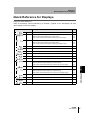
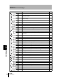
Quick Reference for Displays
127
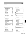
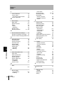
INDEX
131
Revision History
136
ZJ-SD
User’s Manual
Section 1
Section 1
FEATURES
FEATURES
ZJ-SD Features
2
ZJ-SD
User’s Manual
1
Section 1
ZJ-SD Features
ZJ-SD Features
Section 1 FEATURES
The ZJ-SD is a series of static electricity sensors. The purpose of these sensors is to measure
the electric potential of the surface of a workpiece charged with static electricity.
Example: Measurement of the potential of a PCB
Measured value outputs
Judgment outputs
High-precision Detection by Distance Correction
The sensor that measures the charged amount of the workpiece is greatly dependent
on the distance up to the workpiece.
The ZJ-SD series can be connected to a ZX displacement sensor so that distance
correction can be performed on the charged amount using that measurement data and
non-uniform workpieces can be measured to high precision.
Also, if the installation distance up to the workpiece is fixed beforehand, distance
correction can be performed and highly accurate measurement ensured by directly
inputting the distance to the ZJ-SD.
Calculating Unit
2
ZJ-SD
User’s Manual
Section 1
ZJ-SD Features
Extendable Sensor Head Cables
Special extension cables are provided to extend the Sensor Heads.
Section 1 FEATURES
p.6
Special extension cable
Monitoring Measurement Status
Confirm Measurement Status on a Personal Computer
Use an Interface Unit and Static Electricity Smart Monitor to view measurement
waveforms and log measurement data on a personal computer. This function is useful
for making on-site measurement adjustments and for day-to-day quality control.
p.12, p.124
Interface
Unit
Amplifier Unit
Static Electricity
Smart Monitor
ZJ-SD
User’s Manual
3
Section 1
ZJ-SD Features
MEMO
Section 1 FEATURES
4
ZJ-SD
User’s Manual
Section 2
PREPARATION FOR MEASUREMENT
Section 2
6
Part Names and Functions
9
Installing the Amplifier Unit
13
Installing Sensor Heads
15
Mounting on the Mounting Bracket
17
Connections
19
Wiring Input/Output Cables
23
ZJ-SD
User’s Manual
PREPARATION FOR MEASUREMENT
Basic Configuration
5
Section 2
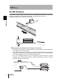
Basic Configuration
Basic Configuration
The basic configuration of the ZJ-SD series of static electricity sensors is shown below.
Use the Sensor Unit and Amplifier Unit in the pre-determined combinations. ZJ-SD Sensor Units and
Amplifier Units cannot be used in combination with ZX series Sensor Units and Amplifier Units.
Section 2 PREPARATION FOR MEASUREMENT
Smart Static Electricity
Monitoring
Enables operation
of Amplifier Units
from the personal
computer and
monitoring
measured values.
Basic Configuration
Personal Computer
Sensor Head
ZJ-SD100
Detects static
electricity.
p.15
Connecting cable
Commercially
available cross cable
p.122
Extension Cable
ZX-XC1A (1 m)
ZX-XC4A (4 m)
ZX-XC8A (8 m)
To be used between
a Sensor Unit and
Amplifier Unit.
Only one extension
cable can be used.
Interface Unit
Amplifier Unit
Used to connect to
a personal computer
or programmable
controller.
ZJ-SDA11
Performs measurements
and outputs measurement
results.
p.22
p.13
Calculating Unit
ZX-CAL2
ZJ-SDA
Used to connect two or
more Amplifier Units.
• Calculating
p.20
Power Supply
DC24V (±10%)
6
ZJ-SD
User’s Manual
Section 2
Basic Configuration
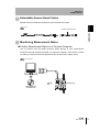
When used in combination with a displacement
sensor
The following shows an example of correcting distance using an ultrasonic type
displacement sensor.
Example 1)
1ch: ultrasonic sensor
The static electricity sensor on 2ch
can perform correction using the data
of the ultrasonic sensor on 1ch.
2ch: static electricity sensor
Example 2)
1ch: ultrasonic sensor
Section 2 PREPARATION FOR MEASUREMENT
When a personal computer (and Amplifier Unit) are not included in
the basic configuration
2ch: static electricity sensor
3ch: static electricity sensor
The static electricity sensor on
2ch to 5ch can perform
correction using the data of
the ultrasonic sensor on 1ch.
4ch: static electricity sensor
5ch: static electricity sensor
When a personal computer (and Amplifier Unit) are included in the
basic configuration
The [Reference destination setting] can be set in the Static Electricity Smart Monitor.
ZJ-SD
User’s Manual
7
Section 2
Basic Configuration
Example 1)
1ch: ultrasonic sensor
2ch: static electricity sensor
Section 2 PREPARATION FOR MEASUREMENT
(When [Reference destination
setting] is set to [CH1]),
3ch: static electricity sensor the static electricity sensor on
2ch to 4ch can perform
correction using the data of
the ultrasonic sensor on 1ch.
4ch: static electricity sensor
0ch: Interface Unit
Example 2)
1ch: ultrasonic sensor
2ch: static electricity sensor
3ch: ultrasonic sensor
4ch: static electricity sensor
0ch: Interface Unit
8
ZJ-SD
User’s Manual
*(When [Reference
destination setting] is set to
[Next CH]),
the static electricity sensor on
2ch and 4ch can perform
correction using the data of
the ultrasonic sensors on 1ch
and 3ch, respectively.
*4ch cannot reference 1ch
and 2ch cannot reference
3ch.
Section 2
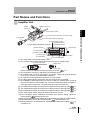
Part Names and Functions
Part Names and Functions
Amplifier Unit
Display
Operating Section (*)
Section (*)
(3) Connector (two connectors, one on each side)
(1) Input Cable
(2) Current/voltage switch (on rear side)
(*) Operating and Display
(5) Power supply indicator
(6) Zero Reset indicator
(7)ENABLE indicator
Sections
(8) OPE1 indicator
POWER
POWER
(15) Control Keys
kV
kV
(9) OPE2 indicator
(10) OPE3 indicator
(11) Main Display
(12) Sub-display
(14) Mode switch
(13) Threshold switch
(1) The input cable connects the Sensor Head.
(2) The current/voltage switch selects either current output or voltage output.
Current/voltage switch
Section 2 PREPARATION FOR MEASUREMENT
(4) Output Cable
Voltage output
Current output
(3)
(4)
(5)
(6)
(7)
(8)
Monitor focus must also be set when switching the output.
p.70
The connectors connect the Calculating and Interface Units.
The output cable connects the sensor to the power supply and external devices,
such as sync sensors or programmable controllers.
The power indicator lights when the Sensor is powered ON.
The Zero Reset indicator lights when the zero reset function is enabled.
The ENABLE indicator lights when the sensor is ready for measurement. It goes off
when measurement is not possible (e.g. when the measuring range is exceeded, or
when the Sensor Head is not connected when the power is turned ON).
The OPE1 indicator lights according to the judgment result or warning state.
p.10
(9) The OPE2 indicator lights according to the judgment result or warning state.
p.10
(10)The OPE3 indicator lights according to the judgment result or warning state.
p.10
(11)The main display shows measured values and function names.
(12)The sub-display shows additional information and function setting values for
Reading Displays p.29
measurements.
(13)The threshold switch selects whether to set (and display) the HIGH or LOW threshold.
(14)The mode switch selects the operating mode.
Switching Modes p.28
(15)The Control Keys set measurement conditions and make other settings.
Key
Operations p.30
ZJ-SD
User’s Manual
9
Section 2
Part Names and Functions
Judgment results/warning states and indicators
Hold
Output type
OPE1
OPE2
OPE3
Other than peak and bottom
hold
Standard
HIGH
PASS
LOW
Warning
WARN
OK
NG
Peak and bottom hold
Warning/
standard
WARN
Peak-OK
Bottom-OK
OK: ON when PASS
Section 2 PREPARATION FOR MEASUREMENT
10
NG: ON whether other than PASS (HIGH or LOW)
WARN: ON in warning state
Peak-OK: ON when the peak hold result is OK (PASS)
Bottom-OK: ON when the bottom hold result is OK (PASS)
The warning state continues until one of "Reset input ON", "Switch to FUN mode" and "Power OFF"
is executed.
ZJ-SD
User’s Manual
Section 2
Part Names and Functions
Sensor Head
Sensor Head
Sensing section
Section 2 PREPARATION FOR MEASUREMENT
Preamplifier
Connector
Connect to the Amplifier Unit.
Calculating Unit
Display (*)
Connector (two connectors, one on each side)
Connect to the Amplifier Unit.
* Display
Connection indicator
Lit when the Amplifier Unit is connected.
ZJ-SD
User’s Manual
11
Section 2
Part Names and Functions
Interface Unit
Display (*)
(2) Amplifier Unit connector
Section 2 PREPARATION FOR MEASUREMENT
(1) Connector
* Display
(3) Power supply indicator
(4) Sensor communication indicator (BUSY/ERR)
(5) External terminal communication indicator (BUSY/ERR)
(1) The communications connector connects the communications cable to the
computer.
(2) The Amplifier Unit connector connects to the Amplifier Unit.
(3) The power supply indicator lights while the power is supplied.
(4) BUSY : Lights during communications with the Smart Sensor.
ERR : Lights if an error occurs during communications with the Smart Sensor.
(5) BUSY : Lights during communications with the personal computer.
ERR : Lights if an error occurs during communications with the personal computer.
12
ZJ-SD
User’s Manual
Section 2
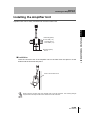
Installing the Amplifier Unit
Installing the Amplifier Unit
Amplifier Units can be easily mounted onto the 35-mm DIN Track.
PFP-100N (1 m)
PFP-50N (0.5 m)
PFP-100N2 (1 m)
End Plate (option)
PFP-M
Installation
Hook the connector end of the Amplifier Unit on the DIN Track and press in at the
bottom until the Unit locks into place.
Section 2 PREPARATION FOR MEASUREMENT
DIN Track (Option)
Hook on the connector end
Always hook the connector end of the Amplifier Unit on the DIN Track first. The mounting strength
may decrease if the output cable end is hooked on the DIN Track first.
ZJ-SD
User’s Manual
13
Section 2
Installing the Amplifier Unit
Removal Method
Push the Amplifier Unit up and pull out from the connector end.
Section 2 PREPARATION FOR MEASUREMENT
Using the Product in Conformance with CE
To use this product in conformance with CE, install the enclosed ferrite core as shown
below.
10 mm max.
Ferrite core
14
ZJ-SD
User’s Manual
Section 2
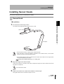
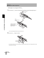
Installing Sensor Heads
Installing Sensor Heads
This section describes how to install Sensor Heads.
Sensor Head
Section 2 PREPARATION FOR MEASUREMENT
Installation
1. Fix the Sensor Head using screws.
The screws must be tightened with a torque of 0.5 Nm or less.
Sensor Head
Preamplifier
Connector
• Mount the Sensor Head in a stable location with little vibration.
• When this sensor is used and installed in combination with a distance sensor, we recommend
using the exclusive mounting bracket (ZJ-XBU1).
• Do not allow anything to touch the metal case of the Sensor Head. Failure to do so might prevent
accurate measurement by the sensor.
Setting the Installation Distance p.41, Scaling p.99
2. Adjust the angle of the Sensor Head.
Loosen the two screws on the sides of the holder, and adjust the angle of the Sensor Head so that it faces
the object to be measured.
Do not remove the screws.
3. Tighten the screws on the sides of the holder to set the angle.
Firmly tighten both screws to a maximum torque of 0.5 N·m.
ZJ-SD
User’s Manual
15
Section 2
Installing Sensor Heads
Preamplifier
Installation
1. Use M3 screws to fix the enclosed Preamplifier
mounting bracket.
Section 2 PREPARATION FOR MEASUREMENT
Use the ZX-XBT2 Preamplifier DIN Track Mounting Bracket
(order separately) when mounting the Preamplifier onto a
DIN Track.
2. Fit one end of the Preamplifier into the bracket.
3. Fit
Fit one end into the bracket.
the other end of the Preamplifier into the
Fit the other end
into the bracket.
bracket.
To remove the Preamplifier from the mounting
[Removal]
bracket, lift upwards while holding the center of the
Preamplifier.
Lift while holding the center.
Using the Product in Conformance with CE
To use this product in conformance with CE, loop the cable twice around the enclosed
ferrite core as shown below.
Sensor
Two loops
10 mm max.
Ferrite core
Amplifier
16
ZJ-SD
User’s Manual
Section 2
Mounting on the Mounting Bracket
Mounting on the Mounting Bracket
The following describes how to mount the laser type Smart Sensor (ZX-LD) and static
electricity sensor (ZJ-S), or ultrasonic type Smart Sensor (ZX-UD) and static electricity sensor
(ZJ-S) onto the exclusive mounting bracket (ZJ-XBU1).
Setting the Installation Distance p.41
Section 2 PREPARATION FOR MEASUREMENT
Installation
Example of mounting the ZX-LD___
1. Fix the ZX-LD___ onto the mounting bracket (ZJ-XBU1) using M3 screws.
Emitting/receiving
section
The screws must be tightened with a torque of 0.3 Nm or less.
Take care not to touch the emitting/receiving section of the Sensor Head. Adhesion of finger marks may
prevent correct measurements. If you have touched them, wipe them with a clean, soft cloth.
2. Fix the ZJ-S___ using the screws.
Sensing
section
Do not allow anything to touch the metal case of the Sensor Head. Failure to do so might prevent accurate
measurement by the sensor.
ZJ-SD
User’s Manual
17
Section 2
Mounting on the Mounting Bracket
Example of mounting the ZX-UD__
1. Fix the ZX-UD__ onto the mounting bracket (ZJ-XBU1) using the M18 tightening nut.
18.5 mm dia.
(+0.5/0)
Section 2 PREPARATION FOR MEASUREMENT
Wave
emitting/receiving
section
Tighten by holding the
M18 tightening nut
(supplied) between your
fingers to secure.
The nut must be tightened with a torque of 45 Nm or less.
2. Fix the ZJ-S___ using the screws.
Sensing
section
Do not allow anything to touch the metal case of the Sensor Head. Failure to do so might prevent accurate
measurement by the sensor.
18
ZJ-SD
User’s Manual
Section 2
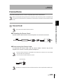
Connections
Connections
This section describes how to connect component parts of the Smart Sensor.
Before connecting/disconnecting Smart Sensor components, make sure that the power to the Amplifier Unit
is turned OFF. The Smart Sensor may malfunction if components are connected or removed while the power
is ON.
Section 2 PREPARATION FOR MEASUREMENT
Sensor Head
Do not touch the terminals inside the connector.
Connecting the Sensor Head
Push the Sensor Head connector into the Amplifier Unit connector until it locks.
Disconnecting the Sensor Head
To disconnect the Sensor Head, hold the Sensor Head's connector ring and the
Amplifier Unit connector, and then pull them straight out.
• Be sure to hold the connector of the Amplifier Unit to disconnect it. Failure to do so may damage
the input cable of the Amplifier Unit.
• Do not touch the terminals inside the connector.
Connector Ring
All settings on the Amplifier Unit will be cleared if the Sensor Head is replaced with a different type.
ZJ-SD
User’s Manual
19
Section 2
Connections
Calculating Unit
Use a Calculating Unit to connect Amplifier Units when performing communications
with two or more Amplifier Units.
Up to five Amplifier Units can be connected.
Section 2 PREPARATION FOR MEASUREMENT
Provide power to all connected Amplifier Units.
Connection Method
2
3
4
1
1
1. Open the connector cover on the Amplifier Unit.
Open the connector cover by lifting and sliding it open.
2. Mount the Calculating Unit onto the DIN Track.
3. Slide and connect the Calculating Unit to the Amplifier Unit connector.
4. Slide and connect the second Amplifier Unit to the Calculating Unit connector.
To disconnect the Calculating Unit, perform the above operations in reverse order.
20
ZJ-SD
User’s Manual
Section 2
Connections
Channel Numbers of Amplifier Units
The following diagram shows the channel numbers when two or more Amplifier Units
are connected.
CH4
CH3
CH2
Section 2 PREPARATION FOR MEASUREMENT
CH5
CH1
ZJ-SD
User’s Manual
21
Section 2
Connections
Interface Unit
Use an Interface Unit to connect a personal computer to the Smart Sensor system.
Connection Method
Section 2 PREPARATION FOR MEASUREMENT
2
ZJ
3
-S
DA
1
1. Open the connector cover on the Amplifier Unit.
Open the connector cover by lifting and sliding it open.
2. Mount the Interface Unit onto the DIN Track.
3. Slide and connect the Interface Unit to the Amplifier Unit connector.
To disconnect the Interface Unit, perform the above operations in reverse order.
• When two or more Amplifier Units are used, connect the Interface Unit to the Amplifier Unit with
the highest channel number.
• Communication with the static electricity Smart Monitor is possible via the Interface Unit.
p.124
22
ZJ-SD
User’s Manual
Section 2
Wiring Input/Output Cables
Wiring Input/Output Cables
The input/output cable has the following wires.
Wire the cable correctly. Incorrect wiring may damage the Smart Sensor.
Brown
White
Green
Gray
Black
Shield
Pink
Orange
Purple
Red
(1) 24 VDC power
(2) GND
(3) OPE1 judgment output
(4) OPE2 judgment output
(5) OPE3 judgment output
(6) Linear output
(7) Linear GND
(8) Bank shift input
(9) Zero reset input
(10) Timing input
(11) Reset input
(1) 24 VDC (±10%) power supply is connected to the power supply terminal.
Use a stabilized power supply separate from other devices and power systems for the Amplifier
Unit, when high resolution is required.
(2) The GND terminal is the 0 V power supply terminal. This terminal becomes the
common terminal for inputs/outputs other than linear output.
The 0 V terminal must be grounded in order for measurements to be performed correctly.
(3) The OPE1 indicator lights according to the judgment result or warning state.
p.10
(4) The OPE2 indicator lights according to the judgment result or warning state.
p.10
Section 2 PREPARATION FOR MEASUREMENT
Blue
(5) The OPE3 indicator lights according to the judgment result or warning state.
p.10
(6) The linear output outputs a current or voltage in accordance with the measurement
result.
(7) The linear output GND terminal is the 0 V terminal for the linear output.
• This ground wire must be grounded separately from the other ground wires.
• Always ground the linear output terminal even when linear output is not used.
• When using Calculating Units, make sure that the linear GND lines of the Amplifier Units are
connected to each other.
(8) When this input is ON: The bank is switched using (9), (10), and (11).
(9) (8)=ON: Bank switching is executed.
p.88
p.88
(8)=OFF: The zero reset input is used to execute and clear zero reset.
p.37
(10)The timing input is for signal input from external devices.
p.88
(8)=ON: The bank is specified.
(8)=OFF: Use it for hold function timing. The sub-display indicates [TIMNG] while
the hold function timing is input.
p.56
(11)(8)=ON: The bank is specified.
p.88
(8)=OFF: The reset input resets all measurement processing and outputs. The subdisplay indicates [RESET] while the hold function reset is input. The linear and
judgment output signals are output according to the non-measurement settings. If
this reset input switches ON while the hold function is used, the state that was
active before the hold function was set is restored.
p.77
ZJ-SD
User’s Manual
23
Section 2
Wiring Input/Output Cables
I/O Circuit Diagrams
Brown
Section 2 PREPARATION FOR MEASUREMENT
Load
White
OPE1 judgment output
Green
OPE2 judgment output
Gray
OPE3 judgment output
Load
Load
Internal circuit
24 VDC
Blue
GND (0V)
Pink
Bank shift input
Purple
Timing input
Orange
Zero reset input
Red
Reset input
Black
Linear output
Current output
4 to 20 mA
Current/voltage
output Switch
100Ω
24
24 VDC
ZJ-SD
User’s Manual
Voltage
output
± 4V
Load
Shield
Linear GND
Current output: 300 Ω or lower
Voltage output: 10 kΩ or higher
Section 3
BASIC OPERATION
Basic Knowledge for Operation
28
Function Transition Charts
33
Correcting the Measurement Reference Voltage
36
Selecting the Measurement Mode
40
Setting the Installation Distance
41
ZJ-SD
User’s Manual
BASIC OPERATION
26
Section 3
Flow of Operation
25
Section 3
Flow of Operation
Section 3 BASIC OPERATION
Preparation for Measurement
Flow of Operation
Installation and
Connection
Preparation for
Measurement
p.5
Turn ON the power.
Correcting the
Measurement
Reference
Voltage
p.36
Select the measurement mode
(standard/high-precision).
Selecting the
Measurement Mode
p.40
Setting/Changing Measurement Contents
Making Settings According
Setting to Execution of Measurement Conditions
to Your Application
26
ZJ-SD
User’s Manual
Measuring Sheet
Workpieces
p.46
Setting Number of Samples to Average
p.52
Setting the Distance Measurement Mode
p.41
Setting Area Correction
p.85
Using Hold Functions
p.53
Comparing Measured Values
(Differentiation Function)
p.105
Changing Display Scales
p.99
Setting Judgment Conditions
Entering Threshold Values
p.64
Setting Output Contents
Linear Output
p.70
Setting Judgment Output Timing
p.79
Section 3
Flow of Operation
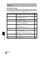
When a Problem Occurs....
The Smart Sensor Does Not
Operate Correctly
Troubleshooting
An Error Message Has Appeared
Error Messages and
Countermeasures
p.110
Want to Find Contents from
Digital Displays
Quick Reference for
Displays
Saving the Zero Reset
Level for the Reference
Voltage in Zero Reset
Memory
Mode
p.95
Additional Functions
p.92
Reversing the Display
during a Zero Reset
p.93
Key Lock Function
p.96
Setting the Warning Level
p.82
Switching Banks
p.88
Changing/Deleting Settings
Applied Use of Functions
Display Digits
p.127
Using the Power-Saving
p.38
Changing the Number of
Section 3 BASIC OPERATION
Want to Know Meanings of
Terms
Glossary p.114
p.111
Initializing Setting Data
p.97
ZJ-SD
User’s Manual
27
Section 3
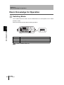
Basic Knowledge for Operation
Basic Knowledge for Operation
Switching Modes
The ZJ-SDA has three modes. Use the Mode Switch on the Amplifier Unit to switch
between modes.
Switch to the desired mode before starting operation.
Section 3 BASIC OPERATION
POWER
kV
Mode
Description
RUN
Normal operation mode
T
Mode for setting the threshold values
FUN
Mode for setting measurement conditions
Function Transition Charts p.33
28
ZJ-SD
User’s Manual
Section 3
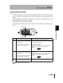
Basic Knowledge for Operation
Reading Displays
The data displayed on the main and sub-displays depends on the currently selected
mode. The sensor is already set to the RUN mode before it was shipped from the
factory.
When the power is turned ON, the model of the Amplifier Unit is displayed on the main
display followed by the number of channels.
The software version is on the sub-display.
This information is displayed for approx. three seconds, followed by the data for each
Main Display
POWER
kV
Sub-display
Mode
RUN
Main display
Sub-display
Displays the measured value (the value Displays the threshold value, voltage, current,
after the measurement conditions have resolution, distance and present value in order when the
Control Keys are pressed.
been reflected).
For example, when the hold function is
set, the held value is displayed.
Section 3 BASIC OPERATION
mode.
Threshold Value Display
Displays either the HIGH or LOW threshold value,
depending on the position of the threshold
switch.
T
Displays the measured value (the value Displays the threshold value for the threshold that is
after the measurement conditions have being set.
been reflected).
Displays either the HIGH or LOW threshold value,
depending on the position of the threshold
For example, when the hold function is switch.
set, the held value is displayed.
FUN
Displays the function names in order
when the Control Keys are pressed.
Displays the setting value for the function displayed on
the main display.
Function Transition Charts p.33
ZJ-SD
User’s Manual
29
Section 3
Basic Knowledge for Operation
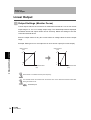
Alphabet Display Format
Alphabet characters appear on the main and sub-displays as shown in the following
table.
A
B
C
D
E
F
G
H
I
J
K
L
M
N
O
P
Q
R
S
T
U
V
W
X
Y
Z
Section 3 BASIC OPERATION
Key Operations
Use the Control Keys to change the display and set measurement conditions.
POWER
kV
Control Keys
The currently selected mode determines the key functions.
Switching Modes p.28
Key
LEFT Key
Function
RUN mode
T mode
Used when selecting the
numeric value digit
The function changes
depending on the setting:
• Switches the function
display.
• Selects the numeric
value digit.
• Stops setting.
Performs timing input.
Used when changing
numeric values
The function changes
depending on the setting:
• Switches between
selections.
• Changes numeric values.
Cursor Keys
RIGHT
Key
UP Key
DOWN Key Resets input.
ENT Key
30
ZJ-SD
User’s Manual
FUN mode
Changes the sub-display
content.
The function changes
When held down for one
depending on the
second: Performs a zero
operation:
reset.
• Confirms the threshold
When held down together
value.
with the Right key for three
seconds: Cancels the zero • Executes teaching.
reset.
Confirms the set condition
or numeric value.
Section 3
Basic Knowledge for Operation
Condition Settings
Display the target function on the main display and select the desired setting value from
the sub-display to set measurement conditions.
This section describes how to set measurement conditions, using an example of
setting a peak hold as the hold condition.
Moving to FUN mode and HOLD
Section 3 BASIC OPERATION
1. Set the mode switch to FUN.
2. Use the LEFT and RIGHT keys to display
[HOLD] on the main display.
Setting Hold Conditions
3. Press the UP or DOWN key.
The sub-display flashes.
4. Use the UP and DOWN keys to select [P-H].
Press either the LEFT or RIGHT key to cancel the
selected option.
The display returns to the current setting ([OFF] in this
example).
5. Press the ENT key to confirm the settings.
This registers the setting.
ZJ-SD
User’s Manual
31
Section 3
Basic Knowledge for Operation
Inputting Numeric Values
This section describes how to input numeric values for threshold and output settings. This
section describes how to input directly, using an example of inputting the low threshold.
Changing the low threshold from "40.000" to "39.000"
Moving to the T mode
Section 3 BASIC OPERATION
1. Set the mode switch to T.
Setting threshold values
2. Set the switch to L.
The measured value is displayed on the main display.
The current setting value is displayed on the sub-display.
3. Press any cursor key.
The first digit on the sub-display flashes to indicate that
direct input is enabled.
4. Use the UP and DOWN keys to display "3".
5. Use the LEFT or RIGHT key to move the
cursor to the one's digit.
6. Use the UP and DOWN keys to display "9".
To cancel the selected setting, use the LEFT key to move
the cursor to the leftmost digit and press the LEFT key
again. Alternatively, use the RIGHT key to move to the
rightmost digit and press the RIGHT key again. The display
will return to the current setting ("40.000" in this example).
7. Press the ENT key to confirm the settings.
The display stops flashing and stays lit, and the setting is
registered.
32
ZJ-SD
User’s Manual
Section 3
Function Transition Charts
Function Transition Charts
Reading Transition Charts
The upper section is the main display and the lower section is the sub-display.
Main Display
Sub-display
Section 3 BASIC OPERATION
RUN Mode
Measured value*1 (The main display always shows the measured value.)
Threshold*1
Linear output voltage value Linear output current value
Resolution
Distance value
Present value
*1 When the mode is switched to RUN, the measured and threshold values are displayed first.
The settings shown in the above diagram are only an example. The actual display may
be different.
p.114
What is the "present value"?
T Mode
There is no function transition in the T mode.
Measured value
Threshold
p.64
The setting shown in the above diagram is only an example. The actual display may be
different.
In the RUN and T modes, the position of the threshold switch determines whether the HIGH or LOW
threshold is displayed.
Threshold switch
HIGH
LOW
ZJ-SD
User’s Manual
33
Section 3
Function Transition Charts
FUN Mode
Number of samples
Measurement mode*1 to average
Hysteresis width
p.40
*1
p.52
Distance
measurement mode
p.69
Sensor distance
value
p.43
p.41
When the mode is
Trigger
switched to FUN, the
Section 3 BASIC OPERATION
measurement mode
p.56
is displayed first.
Trigger direction
Self-trigger level-High
Self-trigger level-Low
Self-trigger
hysteresis width
Bank switching
p.88
Special functions
Differentiation
function
p.106
p.107
Scaling function
Monitor focus
p.74
Differentiation cycle
*2
Linear output
correction
p.70
p.99
Display reverse
ECO Mode
Display digit limit
Displayed if the hold function
is not set to OFF
Warning level
p.82
p.92
Output type
p.82
p.93
p.95
Zero reset memory settings
Non-measurement settings
p.38
Clamp value setting
p.77
All the special functions are displayed if
34
ZJ-SD
User’s Manual
is selected.
Section 3
Function Transition Charts
Area measurement
Area correction
p.86
Timer
Hold
p.79
p.53
p.85
Delay hold
Timer time
p.62
p.63
Special
Sampling period
p.81
p.63
Section 3 BASIC OPERATION
Delay time
Initialization
p.97
This symbol requests you to move to another
menu using the LEFT or RIGHT key after
pressing the ENT key to confirm the selections.
ZJ-SD
User’s Manual
35
Section 3
Correcting the Measurement Reference Voltage
Correcting the Measurement Reference
Voltage
More accurate measurement results can be obtained by correcting the potential used as a
reference in taking measurements (i.e., resetting zero).
As shown below, zero is reset by using a recommended reference detection object that is
grounded.
Conditions for Recommended Reference Detection Object
Section 3 BASIC OPERATION
A
B
Reference detection object
L1
Material: Conductive metal plate
Dimension A ≥ 5L1
Dimension B ≥ 5L1
Thickness (t) ≥ 1 mm
A and B must be at
least 5 times the
installation distance L1
• Accurate measurements may not be possible if the object being used as the reference detection
body carries a static charge because there is a charged object nearby or because the plate is not
grounded properly.
• The same measurement results can be obtained with a jig or other object as long as the
conditions given for the reference detection object are met.
Linearity (Reference Values)
The linearity shown in the following graph can be obtained by resetting zero as
described above.
5.0
Linearity
[%FS]
4.0
3.0
2.0
1.0
0.0
−1.0
−2.0
−3.0
−4.0
−5.0
−6 kV
Set voltage [kV]
−4 kV
−2 kV
0 kV
2 kV
4 kV
6 kV
Note: The graph shows measurement data with n = 8.
36
ZJ-SD
User’s Manual
Section 3
Correcting the Measurement Reference Voltage
Resetting Zero
The measurement value is used as a reference value to reset zero when a key
operation is performed or an external signal is input.
If the reference voltage was previously corrected, the previous correction will be
overwritten. With the default setting, the correction value will be saved in memory even
when the power supply is turned OFF. The setting can be changed so that the
correction value is not saved.
Saving the Zero Reset Level for the Reference Voltage in Zero Reset Memory p.38
Section 3 BASIC OPERATION
1. Place the reference sensing object in position.
2. Set the mode switch to RUN.
3. Press the ENT key at least one second or
input the zero reset signal from an external
device (for 800 ms max.).
This registers the reference value, and the zero reset
indicator lights.
The tolerance for the registered reference value is displayed on the main display.
Clearing the Reference Voltage Correction Value
1. Set the mode switch to RUN.
2. Hold the ENT and RIGHT keys down together
for at least three seconds.
To cancel zero reset from an external device,
input the zero reset signal for at least one
second.
Zero reset is canceled and the zero reset indicator turns OFF.
ZJ-SD
User’s Manual
37
Section 3
Correcting the Measurement Reference Voltage
Saving the Zero Reset Level for the Reference Voltage
in Zero Reset Memory
A setting can be changed to specify whether the zero reset level is saved or cleared
when the power supply is turned OFF.
Setting
ON (default)
The zero reset level is saved when the power supply is turned OFF.
OFF
The zero reset level is cleared when the power supply is turned OFF.
Section 3 BASIC OPERATION
38
Description
• Turn ON the zero reset memory to save the zero reset level and use it again when power is
turned back ON.
If zero reset memory is turned ON, the zero reset level will be written to EEPROM in the Amplifier
Unit every time zero is reset. The write life of the EEPROM is 100,000 writes. If the zero reset
level is written every time measurements are taken, malfunction may occur. Manage the write life
when turning ON zero reset memory during operation.
• Even if the zero reset memory is turned OFF, the zero reset level will be saved whenever
threshold values or other function settings are changed. In this case, the zero reset level will not
be cleared the next time the power supply is turned ON.
ZJ-SD
User’s Manual
Section 3
Correcting the Measurement Reference Voltage
Moving to the FUN mode and SPCL
1. Set the mode switch to FUN.
2. Use the LEFT and RIGHT keys to display
[SPCL] on the main display.
Section 3 BASIC OPERATION
Moving to ZRMEM
3. Press the UP or DOWN key.
The sub-display flashes.
4. Use the UP and DOWN keys to display [ETC]
or [ALL].
5. Press the ENT key.
6. Use the LEFT and RIGHT keys to display
[ZRMEM] on the main display.
Selecting whether or not to enable zero reset memory
7. Press the UP or DOWN key.
The sub-display flashes.
8. Select either [ON] or [OFF].
ON: Zero reset memory enabled
OFF: Zero reset memory disabled (default)
9. Press the ENT key to confirm the setting.
This registers the setting.
ZJ-SD
User’s Manual
39
Section 3
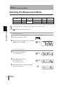
Selecting the Measurement Mode
Selecting the Measurement Mode
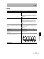
The ZJ-SD has two measurement modes, the standard mode and the high-precision mode.
Mode
Standard mode
Measurement
distance range
Selection
STAND
High-precision mode HI-AC
5 to 100 mm
Display
resolution
Digit number after
the decimal point
±50 kV
10 V
2 figures
±5 kV
1V
3 figures
Section 3 BASIC OPERATION
Select the measurement mode before implementing the distance correction function.
Distance correction function p.41
Moving to the FUN mode
1. Set the mode switch to FUN.
2. Use the LEFT and RIGHT keys to display
[MEAS] on the main display.
Setting the measurement mode
3. Press the UP or DOWN key.
The sub-display flashes.
4. Select [STAND] or [HI-AC].
STAND: Standard mode
HI-AC: High-precision mode
5. Press the ENT key to confirm the settings.
This sets the selected mode.
40
Maximum
measurement voltage
ZJ-SD
User’s Manual
Section 3
Setting the Installation Distance
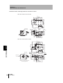
Setting the Installation Distance
Set the distance between the static electricity sensor and the workpiece.
The electric potential value can be corrected according to the change in the distance between the
workpiece and the Sensor Head by performing measurement in combination with a displacement
sensor. The mode to be selected changes according to conditions, such as changes in the
distance between the workpiece and the Sensor Head, or use of the exclusive mounting bracket.
Mode
Description
USER mode
USER
When measurement is performed with the distance between the
workpiece and the Sensor Head fixed
(used on static electricity sensor)
AUTO mode
AUTO
When the exclusive jig is not used when the distance between the
workpiece and the Sensor Head changes
(when the static electricity sensor and distance sensor are fixed by the
user's own jig)
FIX mode
FIX
When the exclusive mounting bracket (ZJ-XBU1) is used to install a laser
type Smart Sensor (ZX-LD) or ultrasonic type Smart Sensor (ZX-UD)
when the distance between the workpiece and the Sensor Head changes
Mode selection criteria
Section 3 BASIC OPERATION
Display
No (fixed)
Does distance between
workpiece and head vary?
Yes
Use exclusive mounting
bracket (ZJ-XBU) (sold separately)
for static electricity sensor and
displacement sensor?
No
Yes
FIX mode
AUTO mode
USER mode
USER mode
Enter the current distance "d" (fixed) between the workpiece and the Sensor Head.
If "d" changes, enter the sensor distance value again.
Static electricity
sensor ZJ-SD
d (60 mm)
Workpiece
ZJ-SD
User’s Manual
41
Section 3
Setting the Installation Distance
AUTO mode
Enter the current distance "d" between the workpiece and the Sensor Head.
Enter the sensor distance value again when the relationship between the static electric
sensor and the displacement sensor changes.
Displacement
sensor
Static electricity
sensor
ZJ-SD
B
Section 3 BASIC OPERATION
A
"d" input
(60 mm)
Workpiece
Amplifier automatically recognizes distance B
(A-d) between displacement sensor and static
electricity sensor by input of "d".
Change in distance with workpiece is sensed
based on this value, and electric potential
value is corrected.
Corrected electric potential value is displayed on amplifier according to distance correction
coefficient held by ZJ-S sensor.
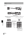
FIX mode
Fix the static electricity sensor (ZJ-SD) and the laser sensor (ZX-LD__) or static
electricity sensor (ZJ-SD) and the ultrasonic sensor (ZX-UD__) to the exclusive
mounting bracket (ZJ-XBU1). Simply setting the FIX mode frees you from the need to
input the distance value.
Mounting bracket (ZJ-XBU1)
Displacement
sensor
Static electricity
sensor
ZJ-SD
B
A
Distance B is stored on amplifier beforehand by securing
onto exclusive mounting bracket.
Change in distance with workpiece is sensed based on
value of A-B, and electric potential value is corrected.
Workpiece
Corrected electric potential value is displayed on amplifier according to distance correction
coefficient held by ZJ-S sensor.
42
ZJ-SD
User’s Manual
Section 3
Setting the Installation Distance
Moving to FUN Mode and DIST
1. Set the mode switch to FUN.
2. Use the LEFT and RIGHT keys to display
[DIST] on the main display.
Section 3 BASIC OPERATION
Setting the Distance Measurement Mode
3. Press the UP or DOWN key.
The sub-display flashes.
4. Select the distance correction method.
5. Press the ENT key to confirm the settings.
This sets the selected mode.
Setting the sensor distance value (when [USER] or [AUTO] is selected in the distance measurement mode)
6. Use the LEFT and RIGHT keys to display
[S-DIS] on the main display.
In the case of [AUTO]/[FIX]: The distance values currently
recognized by the static electric sensor are displayed.
In the FIX mode, the sensor distance values
need not be entered.
7. Press the UP or DOWN key.
The leftmost digit of the sub-display flashes.
8. Measure the sensor distance value.
Moves from one digit
to another.
Changes the numeric value.
9. Press the ENT key to confirm the settings.
This registers the specified distance.
ZJ-SD
User’s Manual
43
Section 3
Setting the Installation Distance
MEMO
Section 3 BASIC OPERATION
44
ZJ-SD
User’s Manual
Section 4
MAIN APPLICATIONS AND SETTING
METHODS
46
Section 4
Measuring Sheet Workpieces
MAIN APPLICATIONS AND SETTING METHODS
ZJ-SD
User’s Manual
45
Section 4
Measuring Sheet Workpieces
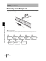
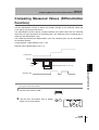
Measuring Sheet Workpieces
This section describes how to measure the electric potential of the surface of a workpiece,
using a PCB as an example.
PCB
Section 4 MAIN APPLICATIONS AND SETTING METHODS
46
Flow of Operation
Place an actual sensing object in position. Have a reference sample ready beforehand.
2
1
Mounting on the
Device
6
Setting the
Measurement
Timing
ZJ-SD
User’s Manual
3
Correcting the
Measurement
Reference
7
Measuring
Reference
Samples
Setting the
Measurement
Mode
4
5
Setting the
Distance
Measurement
Mode
Setting the
Sensor Distance
Value
8
Setting Tolerance
Judgment Values
Section 4
Measuring Sheet Workpieces
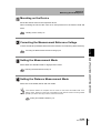
Mounting on the Device
Mount the Sensor Head on the inspection device.
When mounting the sensor, take care not to exert pressure on the Sensor Head and
wires.
Installing Sensor Heads p.15
Correcting the Measurement Reference Voltage
Correct the electric potential that becomes the reference for measuring static electricity.
Setting the Measurement Mode
Select either the standard mode or high-precision mode.
Selecting the Measurement Mode p.40
Setting the Distance Measurement Mode
Select one of the USER, AUTO and FIX modes.
If the distance between the workpiece and the sensor is fixed, select the USER mode. If the
distance varies, select the AUTO mode. If the distance varies and the exclusive mounting bracket
Section 4 MAIN APPLICATIONS AND SETTING METHODS
Correcting the Measurement Reference Voltage p.36
(ZJ-XBU1) is used for securing the sensor, select the FIX mode.
Setting the Installation Distance p.41
ZJ-SD
User’s Manual
47
Section 4
Measuring Sheet Workpieces
Setting the Sensor Distance Value
Set the distance values of the workpiece and sensor.
•
In the USER mode, the distance values are fixed by the specified distance.
•
In the AUTO mode, the positional relationship between the displacement sensor and
the ZJ-SD sensor is registered using preset distances so that distance correction
using the displacement sensor is possible.
In the FIX mode, the sensor distance values need not be entered.
Setting the sensor distance value (when [USER] or [AUTO] is selected in the distance
measurement mode) p.43
Section 4 MAIN APPLICATIONS AND SETTING METHODS
Setting Measurement Timing
Use the bottom hold function to hold the minimum value (bottom) during the sampling
period.
If the timing cannot be entered from the device, select [DIST] at "Hold trigger" so that sampling can
be performed matched to the distance values measured by the distance sensor.
v
Measured value
The bottom value is held.
t
Sampling
Refer to "Section 5 DETAILED SETTINGS" for details on settings.
Using the Hold Functions p.53
48
ZJ-SD
User’s Manual
Section 4
Measuring Sheet Workpieces
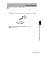
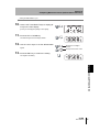
Measuring Reference Samples
The difference in the electric potential with the reference sample is measured using
position teaching and the measurement result is registered as the HIGH threshold
value.
The registered value becomes the reference for the threshold value set in step
6
.
Section 4 MAIN APPLICATIONS AND SETTING METHODS
Refer to "Section 5 DETAILED SETTINGS" for details on settings.
Position Teaching p.66
ZJ-SD
User’s Manual
49
Section 4
Measuring Sheet Workpieces
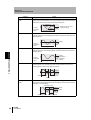
Setting Tolerance Judgment Values
Refer to the HIGH threshold registered in step
and set the upper and lower limits
6
(HIGH and LOW thresholds) for a PASS (OK) judgment.
The judgment result will be output based on the threshold value set here.
Output type = standard: "HIGH" "PASS" "LOW"
Output type = warning: "WARN" "OK" "NG"
Measurement result
Section 4 MAIN APPLICATIONS AND SETTING METHODS
50
Judgment result
Measurement result > HIGH threshold
HIGH
LOW threshold ≤ Measurement result ≤ HIGH threshold
PASS
LOW threshold > Measurement result
LOW
|Measurement result| > warning level (*)
WARN
LOW threshold ≤ measurement result ≤ HIGH threshold
OK
Measurement result > HIGH threshold
Or
LOW threshold > Measurement result
NG
(*)The level is judged by absolute values as plus and minus warning levels exist.
Setting the Warning Level (Output type) p.82
Refer to "Section 5 DETAILED SETTINGS" for details on operation.
Inputting Threshold Values Directly p.65
ZJ-SD
User’s Manual
Section 5
DETAILED SETTINGS
Using the Hold Functions
53
Entering Threshold Values
64
Linear Output
70
Setting Judgment Output Timing (Timer)
79
Setting the Warning Level (Output type)
82
Using the Area Correction Function
85
Selecting Banks
88
ZJ-SD
User’s Manual
DETAILED SETTINGS
52
Section 5
Setting the Number of Samples to Average
51
Section 5
Setting the Number of Samples to Average
Setting the Number of Samples to Average
The average of the measured values obtained based on the preset number of samples can be
output. This setting can be used when you want to ignore rapid changes in measured values.
Note, however, that if this setting is made, the response time for judgment and linear outputs
drops.
Selection for No. of
samples to average
Response time
1
2 ms
2
3 ms
4
5 ms
In the case of the static electricity sensor head, the
number of samples to average has been set to 64
before shipment from the factory.
8
9 ms
In general, when the number of samples to average is
16
17 ms
multiplied by "n", the resolution increases by
32
33 ms
Section 5 DETAILED SETTINGS
64
65 ms
128
129 ms
256
257 ms
512
513 ms
1024
1025 ms
Moving to the FUN mode and AVE
1. Set the mode switch to FUN.
2. Use the LEFT and RIGHT keys to display
[AVE] on the main display.
Selecting the number of samples to average
3. Press the UP or DOWN key.
The sub-display flashes.
4. Use the UP and DOWN keys to select the
desired number of samples to average.
5. Press the ENT key to confirm the setting.
This registers the setting.
52
ZJ-SD
User’s Manual
n .
Section 5
Using the Hold Functions
Using the Hold Functions
The "hold functions" hold data for specific points during the measurement period, such as the
minimum and maximum values, and output those values after measurement ends.
Flow of Operation
3 (If required)
2
1
Selecting the Hold
Setting the Trigger
Set the Trigger
Condition for
for Measurement in
Direction and
Measured Values
the Hold Mode
Self-trigger Level
4 (If required)
Setting the Delay
Time
Selecting the Hold Condition for Measured Values
The time period from the start to the end of hold measurements is called the "sampling
The value to be held during that sampling period is selected here.
After sampling is started, the CLAMP value is output until the first sampling period ends.
What is the "CLAMP value?" p.77
Any of the seven settings shown in the following table can be selected as the hold
condition.
Selection
Details
OFF
(default)
Hold measurement is not performed. The measured value is always output.
P-H (Peak hold)
The maximum value during the sampling period is held. The output changes at
the end of the sampling period and is held until the end of the next sampling
period.
Output
Maximum
value
Current
measured
value
B-H (Bottom hold)
Section 5 DETAILED SETTINGS
period."
Sampling period
The minimum value during the sampling period is held. The output changes at
the end of the sampling period and is held until the end of the next sampling
period.
Current
measured
value
Minimum
value
Output
Sampling period
ZJ-SD
User’s Manual
53
Section 5
Using the Hold Functions
Selection
PP-H (Peak-to-peak
hold)
Details
The difference between the minimum and maximum values is held. Select this
option mainly to detect vibration. The output changes at the end of the sampling
period and is held until the end of the next sampling period.
Current
measured
value
S-H (Sample hold)
Maximum
value
Minimum
value
Output (maximum value
- minimum value)
Sampling period
The measured value at the start of the sampling period is held. The output
changes at the start of the sampling period and is held until the start of the next
sampling period.
Output
Current
measured
value
AVE-H (Average hold)
Section 5 DETAILED SETTINGS
The average measured value during the sampling period is held. The output
changes at the end of the sampling period and is held until the end of the next
sampling period.
Current
measured
value
MASK (Mask hold)
Sampling period
Output
(average of
measured
values)
Sampling period
The measured value is updated only during the sampling period. When the
sampling period ends, the measured value is held until the start of the next
sampling period or until a reset signal is received.
Output
Output
Sampling period
Sampling period
Reset
PB-H (Peak-and-bottom The minimum and maximum values during the sampling period are held.
hold)
The maximum value is displayed on the main display and the minimum value is
displayed on the sub-display.
Maximum value
Maximum
value Output
Minimum
value
Sampling period
54
ZJ-SD
User’s Manual
Minimum
value
Sampling period
Output
Section 5
Using the Hold Functions
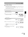
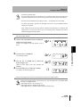
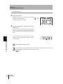
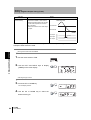
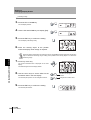
Moving to the FUN mode and HOLD
1. Set the mode switch to FUN.
2. Use the LEFT and RIGHT keys to display
[HOLD] on the main display.
Selecting the hold condition
3. Press the UP or DOWN key.
The sub-display flashes.
4. Use the UP and DOWN keys to select the
desired hold condition.
Section 5 DETAILED SETTINGS
5. Press the ENT key to confirm the setting.
This registers the setting.
ZJ-SD
User’s Manual
55
Section 5
Using the Hold Functions
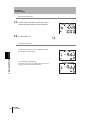
Setting the Trigger for Measurement in the Hold Mode
Use the UP and DOWN keys to select the desired measurement start conditions.
Selection
TIMNG
(Timing input)
Details
Enter the trigger for the start of sampling by using the timing input lead. The
duration that the timing signal from the timing input lead is ON is the sampling
period.
ON
Timing input
OFF
Sampling period
When a delay time is set, the input OFF timing and the end of the
sampling period are not synchronous. Sampling ends after the specified
(default)
DIST
(distance trigger)
sampling period has elapsed.
Section 5 DETAILED SETTINGS
The duration that the displacement sensor detects the specified distance is the
sampling period.
This option can be selected only when a displacement sensor is used.
(Example: When trigger direction = UP)
Trigger direction: UP
Trigger level
Displacement sensor
measured value
Sampling period
Specify the trigger direction, self-trigger level and self-trigger hysteresis
width.
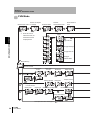
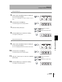
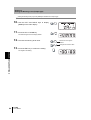
Selecting the trigger type
1. Use the LEFT and RIGHT keys to display
[H-TRG] on the main display.
H-TRG is not displayed if the hold condition is set to
[OFF].
2. Press the UP or DOWN key.
The sub-display flashes.
56
Sampling period
ZJ-SD
User’s Manual
Section 5
Using the Hold Functions
3. Use
the UP or DOWN key to select the
desired trigger type.
There are two trigger types: [TIMNG] and [DIST].
4. Press the ENT key to confirm the setting.
This registers the selected trigger type.
SUB
Section 5 DETAILED SETTINGS
ZJ-SD
User’s Manual
57
Section 5
Using the Hold Functions
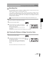
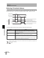
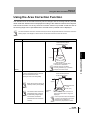
Setting the Trigger Condition
Select the input method for the timing of the start and end of the measurement period.
The trigger mode can be selected only when [DIST] is selected as the hold trigger.
Selection
UP
(Self-up trigger)
Details
The period in which the displacement sensor measured value is greater than the
specified self-trigger level is the sampling period. Hold measurement is possible
without a sync input.
Specify self-trigger level -Low [H-LVL].
Hysteresis width
(for self-trigger)
Self-trigger level
Displacement sensor
measured value
Sampling period
(default)
Section 5 DETAILED SETTINGS
DOWN
(Self-down trigger)
Operation point
Return point
Sampling period
The period in which the displacement sensor measured value is lower than the
specified self-trigger level is the sampling period. Hold measurement is possible
without a sync input.
Specify self-trigger level -High [H-LVH].
Displacement sensor
measured value
Self-trigger level
Hysteresis width
(for self-trigger)
Operation point
Return point
Sampling period
WINDOW
The period in the range between the displacement sensor measured value's high
and low self-trigger levels is the sampling period.
Specify self-trigger level -High [H-LVH] and self-trigger level -Low [H-LVL].
High
Displacement sensor
measured value
Self-trigger level
Low
Sampling period
58
ZJ-SD
User’s Manual
Sampling period
Sampling period
Section 5
Using the Hold Functions
• Hysteresis (hysteresis width)
Set the hysteresis based on the fluctuations in the measured values around the trigger level.
Hysteresis is applied from the start of the sampling period and prevents timing input chattering.
• Zero reset input is disabled during sampling or while [-----] is displayed in the main display.
• The timing input signal is ignored if the self-trigger level is set to [UP] or [DOWN]. However,
sampling is not affected.
• When a delay time is set, the timing when the measured value falls below or exceeds the selftrigger level is not synchronous with the end of the sampling period. Sampling ends after the
specified sampling period has elapsed.
Selecting the trigger direction
1. Use the LEFT and RIGHT keys to display [HTRD] on the main display.
H-TRD is not displayed if the hold condition is set to
[OFF].
Section 5 DETAILED SETTINGS
2. Press the UP or DOWN key.
The sub-display flashes.
3. Use
the UP or DOWN key to select the
desired trigger type.
[There are three trigger types: [UP], [DOWN] and
[WINDW].
4. Press the ENT key to confirm the setting.
This registers the selected trigger type.
Setting the self-trigger level (example: when [WINDW] is selected as the trigger direction)
There are two self-trigger levels, [H-LVH] and [H-LVL]. The self-trigger level to be specified differs
according to the trigger direction.
• When trigger direction = UP, specify [H-LVL].
• When trigger direction = DOWN, specify [H-LVH].
• When trigger direction = WINDOW, specify both [H-LVH] and [H-LVL].
ZJ-SD
User’s Manual
59
Section 5
Using the Hold Functions
5. Use the LEFT or RIGHT key to display
[H-LVH] on the main display.
H-LVH is not displayed if timing input [TIMNG] is set as
the trigger.
6. Press the UP or DOWN key.
The leftmost digit of the sub-display flashes.
7. Use the cursor keys to set the desired
self-trigger level.
Moves from one digit to
another.
Changes the numeric value.
8. Press the ENT key to confirm the setting.
This registers the trigger level.
Section 5 DETAILED SETTINGS
9. Use the LEFT or RIGHT key to display
[H-LVL] on the main display.
H-LVL is not displayed if timing input [TIMNG] is set as
the trigger.
10. Press the UP or DOWN key.
The leftmost digit of the sub-display flashes.
11. Use the cursor keys to set the desired selftrigger level.
Moves from one digit to
another.
Changes the numeric value.
12. Press the ENT key to confirm the setting.
This registers the trigger level.
60
ZJ-SD
User’s Manual
Section 5
Using the Hold Functions
Setting the hysteresis width (when [DIST] is selected as the hold trigger)
13. Use the LEFT and RIGHT keys to display
[H-HYS] on the main display.
H-HYS is not displayed if timing input [TIMNG] is set as
the trigger.
14. Press the UP or DOWN key.
The leftmost digit of the sub-display flashes.
15. Use
the cursor keys to set the hysteresis
width for the trigger level.
Moves from one digit to
another.
Changes the numeric value.
16. Press the ENT key to confirm the setting.
This registers the hysteresis width.
Section 5 DETAILED SETTINGS
ZJ-SD
User’s Manual
61
Section 5
Using the Hold Functions
Setting the Delay Time
Set the delay time function, for example, to ignore measured values immediately after a
hold trigger is detected in order to avoid fluctuation of signals near the sensing object
boundary.
The delay time (the delay between detection of the trigger and start of sampling) and
the sampling period can be set.
The default delay time setting is OFF.
• Make the sum of the delay time and sampling period less than the trigger detection interval.
• If the next trigger input for measurement is detected before the sum of the delay time and sampling
period have elapsed, that trigger input is ignored and is not reflected in sampling.
• Triggers are detected when the hold trigger and trigger condition is satisfied (ex: when the timing
input turns ON)
Delay time
Sampling period
Section 5 DETAILED SETTINGS
ON
Timing input
OFF
Ignored
Moving to the delay hold (H-DLY)
1. Use the LEFT and RIGHT keys to display
[H-DLY] on the main display.
H-DLY is not displayed if the hold condition is set to
[OFF].
2. Press the UP or DOWN key.
The sub-display flashes.
3. Use the UP and DOWN keys to display [ON].
4. Press the ENT key.
The H-DLY function can now be set.
62
Delay time
ZJ-SD
User’s Manual
Accepted
Section 5
Using the Hold Functions
Setting the delay time
5. Use the LEFT and RIGHT keys to display [HD-T] on the main display.
H-D-T is not displayed if the H-DLY function is set to
OFF.
6. Press the UP or DOWN key.
The leftmost digit of the sub-display flashes.
7. Enter the delay time (ms).
Moves from one digit to
another.
Changes the numeric value.
8. Press the ENT key to confirm the setting.
Section 5 DETAILED SETTINGS
This registers the delay time.
Setting the sampling period
9. Use the LEFT and RIGHT keys to display [HS-T] on the main display.
H-S-T is not displayed if the H-DLY function is set to OFF.
10. Press the UP or DOWN key.
The leftmost digit of the sub-display flashes.
11. Use the cursor keys to enter the sampling
period (ms).
Moves from one digit to
another.
Changes the numeric value.
12. Press the ENT key to confirm the setting.
This registers the sampling period.
ZJ-SD
User’s Manual
63
Section 5
Entering Threshold Values
Entering Threshold Values
Threshold values are set to determine the range for PASS judgments. Both HIGH and LOW
threshold values are set. There are three judgment outputs: "HIGH", "PASS" and "LOW".
HIGH threshold
Measured value
LOW threshold
Output
HIGH
ON
OFF
PASS
ON
OFF
LOW
ON
OFF
(ON when the measurement result is
> the HIGH threshold)
(ON when the LOW threshold is ≤ the
measurement result ≤ the HIGH threshold)
(ON when the measurement result is
< the LOW threshold)
Section 5 DETAILED SETTINGS
The following table outlines the three methods for setting the threshold values.
Method
Details
Direct input
The threshold values can be set by directly inputting the numeric values.
Direct input is useful when the criteria is known in advance or when adjusting
threshold values after teaching.
Position teaching
Measurement is actually performed and the measurement results are used to set
threshold values.
Position teaching is useful when charge limit samples are available.
Automatic teaching
Measurement is performed continuously while the keys are held down, and the
minimum and maximum measurements during that period are set as the threshold
values.
Automatic teaching is useful when you want to set threshold values by actually
starting the device and obtaining real measurements.
Hysteresis (hysteresis width) can also be set to threshold values. Set hysteresis when judgments are
unstable to prevent chattering.
p.69
64
ZJ-SD
User’s Manual
Section 5
Entering Threshold Values
Inputting Threshold Values Directly
Threshold values can be set by directly inputting numeric values.
Direct input is useful when you know the standard values of the static electricity sensor
or when you want to fine-tune threshold values after teaching.
Moving to the T mode
1. Set the mode switch to T.
Setting threshold values
2. Move the threshold switch to either H or L,
i.e., the threshold to be set.
The current measured value is displayed on the main
display.
depending on the threshold switch setting) is displayed
on the sub-display.
3. Press any cursor key.
The leftmost digit of the sub-display flashes.
4. Use
the cursor keys to set the threshold
value.
Moves from one digit to
another.
Changes the numeric value.
Section 5 DETAILED SETTINGS
The currently set threshold value (either HIGH or LOW,
5. Press the ENT key to confirm the setting.
This registers the setting.
Countermeasures for setting errors
If [ERRLH] or [ERRHL] is displayed, either of the
following errors has occurred:
• HIGH threshold value < LOW threshold value
• HIGH threshold value - LOW threshold value <
hysteresis width
Hysteresis setting p.69
If an error is displayed, the threshold values have not
been updated.
Set the threshold values again.
ZJ-SD
User’s Manual
65
Section 5
Entering Threshold Values
Position Teaching
Measurement is actually performed and the measurement results are used to set
threshold values.
Position teaching is useful when threshold samples, i.e., with the upper and lower
limits, can be obtained beforehand.
Teaching point =
HIGH threshold
Sensing object
Teaching point =
LOW threshold
Sensing object
Hold, trigger mode, and scaling settings that have been made before teaching are reflected in the
teaching measurements.
Section 5 DETAILED SETTINGS
Moving to the T mode
1. Set the mode switch to T.
Setting threshold values
2. Move the threshold switch to either H or L,
i.e., the threshold to be set.
The current measured value is displayed on the main display.
The currently set threshold value (either HIGH or LOW,
depending on the threshold switch setting) is displayed
on the sub-display.
3. Place the threshold sample in position.
The main display value changes.
4. Press the ENT key for at least one second
and then release it.
The measured value at the moment that the ENT key is
released is set as the threshold value.
This threshold value is shown on the sub-display.
When [ERRLH] or [ERRHL] is displayed p.65
The threshold values set using position teaching can also be changed using direct input. This is
useful when setting judgment tolerances for measured values.
p.65
66
ZJ-SD
User’s Manual
Section 5
Entering Threshold Values
Automatic Teaching
When automatic teaching is executed, measurement is performed continuously for the
duration that the keys are held down, and the minimum and maximum measurements
during that period are set as the threshold values.
Automatic teaching is useful when you want to set threshold values by actually starting
the device and obtaining real measurements.
Minimum value =
LOW threshold
Maximum value =
HIGH threshold
Move
Sensing object
Hold, trigger mode, and scaling settings that have been made before teaching are reflected in the
teaching measurements.
Moving to the T mode
1. Set the mode switch to T.
Section 5 DETAILED SETTINGS
Sensing object
2. Start the device.
The threshold switch may be set to either position. Both HIGH and LOW thresholds are set,
regardless of the switch setting.
ZJ-SD
User’s Manual
67
Section 5
Entering Threshold Values
Setting threshold values
3. Start measurement.
Measurement continues for the duration that the ENT
and RIGHT keys are held down.
[AUTOT] flashes on the sub-display.
4. To end measurement, release the ENT and
RIGHT keys.
The maximum measured value during the measurement
period is set as the HIGH threshold value and the
minimum measured value is set as the LOW threshold
value.
Section 5 DETAILED SETTINGS
The new threshold value (either HIGH or LOW,
68
depending on the threshold switch setting) is displayed
on the sub-display.
When [ERRLH] is displayed p.65
The threshold values set using automatic teaching can also be changed using direct input. This is
useful when setting judgment tolerances for measured values.
p.65
ZJ-SD
User’s Manual
Section 5
Entering Threshold Values
Hysteresis Setting
Set the hysteresis width (difference between operation and return points) for the upper
and lower limits of judgments if the HIGH, PASS, or LOW judgment is unstable near the
sensing boundaries.
HIGH threshold
Hysteresis (hysteresis width)
Measured value
Operation point
Return point
LOW threshold
Output
HIGH
ON
OFF
PASS
ON
OFF
LOW
ON
OFF
To prevent self-trigger chattering, set hysteresis for the self-trigger.
p.56
Section 5 DETAILED SETTINGS
Moving to the FUN mode and HYS
1. Set the mode switch to FUN.
2. Use the LEFT and RIGHT keys to display
[HYS] on the main display.
3. Press the UP or DOWN key.
The leftmost digit of the sub-display flashes.
4. Use the cursor keys to enter the hysteresis
width.
Moves from one digit to
another.
Changes the numeric value.
5. Press the ENT key to confirm the setting.
This registers the setting.
Countermeasures for setting errors
If [ERROV] is displayed, HIGH threshold - LOW
threshold < the hysteresis width.
If an error is displayed, the threshold values have not
been updated.
Set the values again or change the threshold values.
ZJ-SD
User’s Manual
69
Section 5
Linear Output
Linear Output
Output Settings (Monitor Focus)
"Linear output" refers to the conversion of measurement results to a 3 to 21 mA current
output range or a -5 to +5 V voltage output range. The relationship between displayed
measured values and output values can be set freely. Match the settings to suit the
connected external device.
Enter the output values for any two current values or voltage values to set the output
range.
Example: Setting 5 kV to 4 mA output and 15 kV to 20 mA output (for current output)
Output current
Output current
(mA)
(mA)
Section 5 DETAILED SETTINGS
20
20
4
4
0
20
Measured value
(kV)
0
5
15
Measured value
(kV)
Allow at least 1 kV between the two points to specify.
The threshold values are cleared when the monitor focus is set. Reset the threshold values after
setting the monitor focus.
Threshold p.36
70
ZJ-SD
User’s Manual
Section 5
Linear Output
This section describes how to set the output range, using an example of current output
with a range with the following conversions: 5 kV to 4 mA and 15 kV to 20 mA. Change
the values in this example for voltage output as necessary.
Output current
Output current
(mA)
(mA)
20
20
(A)
(B)
4
4
Measured value
0
20
(kV)
Measured value
0
5
15
(kV)
1. Turn OFF the Amplifier Unit.
Section 5 DETAILED SETTINGS
2. Move
the current/voltage switch to current
output. The switch is located on the bottom of
the Amplifier Unit.
The default setting is voltage output.
Moving to the FUN mode and SPCL
3. Turn
Voltage output
Current output
ON the Amplifier Unit and move the
mode switch to FUN.
4. Use the LEFT and RIGHT keys to display
[SPCL] on the main display.
Moving to FOCUS
5. Press the UP or DOWN key.
The sub-display flashes.
6. Use the UP and DOWN keys to display [SET]
or [ALL].
7. Press the ENT key.
ZJ-SD
User’s Manual
71
Section 5
Linear Output
8. Use the LEFT and RIGHT keys to display
[FOCUS] on the main display.
Selecting current (mA) or voltage (V) output
9. Press the UP or DOWN key.
The sub-display flashes.
10. Display [mA].
Always select the same output as the current/voltage switch selection on the bottom of the Amplifier
Unit.
Setting the first point (A)
Section 5 DETAILED SETTINGS
11. Press the ENT key.
The display changes to the display for setting the first
point (A).
The output current value is displayed on the main
display.
The corresponding measured value is displayed on the
sub-display and the leftmost digit flashes.
12. Set
the
output
current
value
and
the
Moves from one digit to
corresponding measured value for the first point.
another.
Set a measured value within the measuring range. If
Changes the numeric value.
scaling or calculation has been set, set a value that
reflects those settings.
The flashing digit, i.e., the digit to which a value can be set, changes as shown in the diagram.
Digit shift on sub-display
Shifts one digit
at a time.
Switching from the sub-display to the main
display and vice versa (from the leftmost/
rightmost digit of the sub-display)
72
ZJ-SD
User’s Manual
Section 5
Linear Output
13. Press the ENT key to confirm the setting.
This confirms the setting for the first point.
The screen for setting the second point is displayed.
Setting the second point (B)
14. Use the same procedure as for the first point
to
set
the
corresponding
output
current
measured
value
value
for
and
the
second point.
15. Press the ENT key to confirm the setting.
Section 5 DETAILED SETTINGS
Confirming completion of monitor focus settings
The display indicates [OK] if monitor focus has been set
correctly.
If not, the display indicates [NG].
If [NG] is displayed, check the following points and
execute the monitor focus again.
• Is the measured value set on the sub-display within the
measuring range (with scaling and calculation settings
reflected if set)?
• Are the measured values of the first and second points
separated by at least 1% of the rated measuring range?
• Are the current (or voltage) values for the two points the
same?
ZJ-SD
User’s Manual
73
Section 5
Linear Output
Correcting Linear Output Values
Discrepancies may occur between the linear output current (or voltage) values set on
the Amplifier Unit and the actual current (or voltage) values measured due to the
conditions for the connected external device or other factors. The linear output
correction function can be used to correct this discrepancy.
Output values are corrected by entering the correction value for the current (or voltage)
values of any two points.
Set the monitor focus function and select either current or voltage output beforehand.
p.70
This section uses current output as an example. Change the values in this example for
voltage output as necessary.
Section 5 DETAILED SETTINGS
1. Connect the linear output to an external ammeter.
Moving to the FUN mode and SPCL
2. Turn
ON the Amplifier Unit and move the
mode switch to FUN.
3. Use the LEFT and RIGHT keys to display
[SPCL] on the main display.
Moving to L-ADJ
4. Press the UP or DOWN key.
The sub-display flashes.
5. Use the UP and DOWN keys to display [SET]
or [ALL].
74
ZJ-SD
User’s Manual
Section 5
Linear Output
6. Press the ENT key.
7. Use the LEFT and RIGHT keys to display [LADJ] on the main display.
The units for the monitor focus settings (mA or V) are
displayed on the sub-display.
8. Press the ENT key.
The display changes to the display for setting the first
point (A).
The output current value is displayed on the main
display.
The correction value is displayed on the sub-display and
the leftmost digit flashes.
Setting the first point (A)
Moves from one digit to
for the first point.
another.
Adjust the correction value on the sub-display so that the
Changes the numeric value.
ammeter reading and the output current shown on the
main display are the same.
The larger the correction value, the larger the output current.
The correction value can be set within the range -999 to 999.
To set a negative value, make the leftmost digit of the
sub-display flash and change the value.
If the correction value changes by 4, the linear output will
change by approx. 1.4 µA (0.7 mV).
Section 5 DETAILED SETTINGS
9. Set the output current and correction values
The flashing digit, i.e., the digit to which a value can be set, changes as shown in the diagram.
Digit shift on sub-display
Shifts one
digit at a time.
Switching from the sub-display to the main
display and vice versa
(from the leftmost/rightmost digit of the
sub-display)
10. Press the ENT key to confirm the setting.
This confirms the correction value for the first point.
The screen for setting the second point is displayed.
ZJ-SD
User’s Manual
75
Section 5
Linear Output
Setting the second point (B)
11. Use the same procedure as the first point to
set the correction value for the second point.
12. Press the ENT key.
Confirming setting results
If linear output correction has been registered correctly,
Section 5 DETAILED SETTINGS
the sub-display will show [OK].
76
If not, the display indicates [NG].
Check that the current (or voltage) values for the two
points are not the same and execute again.
ZJ-SD
User’s Manual
Section 5
Linear Output
Output Settings for Non-measurement
The linear output method for when a reset is input can be set.
Outputs
Selection
Judgment outputs
Linear output
KEEP
(default)
The measured value immediately before measurement is stopped is held and output.
CLAMP
All outputs turn OFF.
The set CLAMP value is output.
The following options are available:
• At current output: 3 to 21 mA or maximum
(approx. 23 mA)
• At voltage output: -5 to 5 V or maximum (approx.
5.5 V)
• In the case of hold measurement
Even if [KEEP] is set, the output before the first hold value is obtained is the same as [CLAMP].
• Even in FUN mode, the outputs are made according to the non-measurement settings.
Section 5 DETAILED SETTINGS
Moving to the FUN mode and SPCL
1. Set the mode switch to FUN.
2. Use the LEFT and RIGHT keys to display
[SPCL] on the main display.
Moving to RESET
3. Press the UP or DOWN key.
The sub-display flashes.
4. Use the UP and DOWN keys to display [ETC]
or [ALL].
5. Press the ENT key.
ZJ-SD
User’s Manual
77
Section 5
Linear Output
6. Use the LEFT and RIGHT keys to display
[RESET] on the main display.
Selecting output status at non-measurement
7. Press the UP or DOWN key.
The sub-display flashes.
8. Use the UP and DOWN keys to select either
KEEP or CLAMP.
9. Press the ENT key to confirm the setting.
Section 5 DETAILED SETTINGS
This registers the setting.
Next, set the clamp value if [CLAMP] is selected.
Setting the clamp value (only when CLAMP is selected)
10. Use the LEFT and RIGHT keys to display
[CLAMP] on the main display.
[CLAMP] is not displayed if [KEEP] has been selected.
11. Press the UP or DOWN key.
The sub-display flashes.
12. Select the clamp value.
13. Press the ENT key to confirm the setting.
This registers the setting.
78
ZJ-SD
User’s Manual
Section 5
Setting Judgment Output Timing (Timer)
Setting Judgment Output Timing (Timer)
The timing of judgment outputs can be adjusted to match the operation of external devices.
Selection
OFF
Details
The judgment is output as soon as the
judgment result has been confirmed.
Measured value
HIGH threshold
LOW threshold
HIGH output
ON
OFF
PASS output
ON
OFF
LOW output
ON
OFF
OFF-D
(OFF-delay timer)
After the judgment result has been
confirmed, changing of the PASS
output state to OFF is delayed by the
time set to the timer.
Also, changing of the HIGH and LOW
output states to ON is delayed by the
time set to the timer.
Measured value
HIGH threshold
LOW threshold
HIGH output ON
OFF
Timer time
PASS output ON
OFF
Section 5 DETAILED SETTINGS
(default)
Timer time
LOW output
ON-D
(ON-delay timer)
After the judgment result has been
confirmed, changing of the PASS
output state to ON is delayed by the
time set to the timer.
Also, changing of the HIGH and LOW
output states to OFF is delayed by the
time set to the timer.
ON
OFF
Measured value
HIGH threshold
LOW threshold
HIGH output
ON
OFF
PASS output
ON
OFF
LOW output
ON
OFF
Timer time
Timer time
ZJ-SD
User’s Manual
79
Section 5
Setting Judgment Output Timing (Timer)
Selection
1-Sht
(One-shot timer)
Details
When the judgment result changes
from HIGH to PASS or from LOW to
PASS, the PASS output turns ON with
a pulse width equivalent to the time
set to the timer.
Neither the HIGH nor the LOW output
is output.
Measured value
HIGH threshold
LOW threshold
HIGH output
ON
OFF
PASS output
ON
OFF
LOW output
ON
OFF
Timer time
The following description uses the OFF-delay timer as an example. Change the values in this
example if other timers are used.
Section 5 DETAILED SETTINGS
Moving to the FUN mode and TIMER
1. Set the mode switch to FUN.
2. Use the LEFT and RIGHT keys to display
[TIMER] on the main display.
Selecting the type of timer
3. Press the UP or DOWN key.
The sub-display flashes.
4. Use
the UP or DOWN key to select the
desired timer type.
80
ZJ-SD
User’s Manual
Section 5
Setting Judgment Output Timing (Timer)
5. Press the ENT key to confirm the setting.
This registers the setting.
If anything other than [OFF] is selected, set the timer
time by the following procedure.
Setting the timer time (when a timer type other than [OFF] is selected)
6. Use the LEFT and RIGHT keys to display [T-TIM] on the main display.
T-TIM cannot be displayed if [OFF] is selected.
7. Press the UP or DOWN key.
8. Use
the cursor keys to set the timer time
(ms).
Moves from one digit to
another.
Changes the numeric value.
9. Press the ENT key to confirm the setting.
This registers the setting.
ZJ-SD
User’s Manual
Section 5 DETAILED SETTINGS
The leftmost digit of the sub-display flashes.
81
Section 5
Setting the Warning Level (Output type)
Setting the Warning Level (Output type)
Threshold values (warning level) other than HIGH, PASS or LOW can be set and displayed.
Selection
STAND
(standard)
Details
The warning level is not set.
Only the HIGH, PASS or LOW
judgments are output.
When timer = OFF
Measured value
HIGH threshold
LOW threshold
(default)
Section 5 DETAILED SETTINGS
WARN
(warning)
The warning level is set.
Next, specify the warning level value.
• The warning status
continues to be output until
one of "reset input ON",
"switching to FUN mode" or
"power OFF".
• The warning level value is
set to the plus and minus
directions.
(Example: When "15" is
specified, the +15 and -15
become the warning level
values.)
HIGH output
ON
OFF
PASS output
ON
OFF
LOW output
ON
OFF
When timer = OFF
Measured value
Warning level
(+ side)
HIGH threshold
LOW threshold
Warning level
(- side)
Warn output
ON
OFF
OK output
ON
OFF
NG output
ON
OFF
Reset input ON
Judgment output (judgment indicator)
Hold
Output type
OPE1
HIGH
OPE2
PASS
Other than peak and bottom
hold
Standard
Warning
WARN
OK
NG
Peak and bottom hold
Not related
WARN
Peak-OK
Bottom-OK
OK: Judged as PASS
NG: Other than PASS (HIGH or LOW)
WARN: ON in warning state
Peak-OK: ON when the peak hold result is OK (PASS)
Bottom-OK: ON when the bottom hold result is OK (PASS)
82
ZJ-SD
OPE3
User’s Manual
LOW
Section 5
Setting the Warning Level (Output type)
Moving to the FUN mode and OUTPT
1. Set the mode switch to FUN.
2. Use the LEFT and RIGHT keys to display
[SPCL] on the main display.
3. Press the UP or DOWN key.
The sub-display flashes.
4. Use the UP and DOWN keys to display [ETC]
or [ALL].
Section 5 DETAILED SETTINGS
5. Press the ENT key.
6. Use the LEFT and RIGHT keys to display
[OUTPT] on the main display.
Selecting the output type
7. Press the UP or DOWN key.
The sub-display flashes.
8. Select the output type.
When a warning level is set, select [WARN], and when
not set, select [STAND].
9. Press the ENT key to confirm the setting.
This registers the setting.
When [WARN] is selected, set the warning level.
ZJ-SD
User’s Manual
83
Section 5
Setting the Warning Level (Output type)
Setting the warning level (only when [WARN] is selected as the output type)
10. Use the LEFT and RIGHT keys to display
[WARN] on the main display.
11. Press the UP or DOWN key.
The leftmost digit of the sub-display flashes.
12. This sets the warning level value.
Moves from one digit to
another.
Changes the numeric value.
13. Press the ENT key to confirm the setting.
This registers the setting.
Section 5 DETAILED SETTINGS
84
ZJ-SD
User’s Manual
Section 5
Using the Area Correction Function
Using the Area Correction Function
The detection area of the static electricity sensor changes and the average electric potential
value inside the detection area is displayed according to the distance between the workpiece
and the sensor head. This is why the area correction function is provided so that the area of
the sensing target can be specified and an accurate electric potential can be displayed.
The area sometimes cannot be corrected correctly due to the charged state and the environment around the
sensing object. If this happens, use the sensor with the area correction function set to OFF.
Selection
OFF
Details
The entire area is measured.
Static Electricity Sensor
ZJ-SD Sensor Head
W dia. (mm)
d' (mm)
W' dia. (mm)
Average electric potential value
of W and W' is calculated.
Detection area (W, W') differs
according to distance (d, d') between
workpiece and sensor head.
(default)
ON
The electric potential in a particular size
of area is calculated from the value for
the entire measurement area.
Specify the size of the area [SIZE].
Static Electricity Sensor
ZJ-SD Sensor Head
Section 5 DETAILED SETTINGS
d(mm)
d (mm)
Enter the size of the area to be
sensed (mm dia.) as the [SIZE].
Measurement
area
Z dia. (mm)
This function does not limit the
measurement area. If there is
an electrically charged object
near the area, the electric
potential will not be measured
correctly.
Particular
area
W dia. (mm)
Numerical value after correction on
electric potential value in range Z is
displayed.
Electric potential value after distance
correction with detection area (W) is
determined from distance d
measured by displacement sensor.
ZJ-SD
User’s Manual
85
Section 5
Using the Area Correction Function
Moving to the FUN mode and AREA
1. Set the mode switch to FUN.
2. Use the LEFT and RIGHT keys to display
[AREA] on the main display.
Selecting area correction
3. Press the UP or DOWN key.
The sub-display flashes.
Section 5 DETAILED SETTINGS
4. Select
whether or not to enable the area
correction function.
To use the area correction function, select [ON].
5. Press the ENT key to confirm the setting.
This registers the setting.
Next, set the area size if [ON] is selected.
Setting the area size (only when [ON] is selected)
6. Use the LEFT and RIGHT keys to display
[SIZE] on the main display.
SIZE is not displayed if [OFF] is selected.
7. Press the UP or DOWN key.
The leftmost digit of the sub-display flashes.
86
ZJ-SD
User’s Manual
Section 5
Using the Area Correction Function
8. Set the size of the area.
Moves from one digit to
Enter the size of the area to be sensed (mm dia.) as the
another.
[SIZE].
Changes the numeric value.
9. Press the ENT key to confirm the setting.
This registers the setting.
Section 5 DETAILED SETTINGS
ZJ-SD
User’s Manual
87
Section 5
Selecting Banks
Selecting Banks
Up to four setting patterns can be stored in the ZJ-SD, and a set of these patterns is called a
"bank."
• Four banks can be selected.
• Banks are switched by external input leads or the amplifier (bank switching in the FUN mode
[BANK]).
• Switching by external input leads is possible only in the RUN mode.
• Measurement stops during bank switching. Measurement is resumed after the setting data in the
banks is loaded to RAM and setting processing ends.
Bank is switched by [External input lead] or in FUN mode [BANK].
BANK 0
Setting data
BANK 1
Switching
Setting data
BANK 2
Switching
Setting data
BANK 3
Switching
Setting data
Switching
Section 5 DETAILED SETTINGS
Procedure for switching banks from an external input lead
The following describes the procedure for switching banks using external input leads (8), (9), (10) and (11) in
the RUN mode.
Brown
Blue
White
Green
Gray
Black
Shield
Pink
Orange
Purple
Red
(1) 24 VDC power
(2) GND
(3) OPE1 judgment output
(4) OPE2 judgment output
(5) OPE3 judgment output
(6) Linear output
(7) Linear GND
(8) Bank shift input
(9) Zero reset input
(10) Timing input
(11) Reset input
Switching how input leads are to be used
1. Turn the pink (8) Bank shift input ON.
The functions of input leads (9), (10) and (11) change as follows:
Orange (9) Zero reset input → Execution of bank switching
Purple (10) Timing input → Bank selection 1
Red (11) Reset input → Bank selection 2
Turn pink (8) Bank shift input OFF when not switching banks.
88
ZJ-SD
User’s Manual
Section 5
Selecting Banks
Selecting banks
2. Turn (10) Bank input 1 and (12) Bank input 2 ON/OFF.
Banks are specified by the combination of the ON/OFF settings of these two inputs.
Bank No. and External Input Lead
External input lead
Bank No.
Purple (10) Bank input 1
Red (11) Bank input 2
0
OFF
OFF
1
ON
OFF
2
OFF
ON
3
ON
ON
Switching banks
The currently selected bank is switched to at the moment that execution of bank switching input switched
from ON → OFF.
[Bank switching timing]
(BANK 1 switching example)
Execution of
bank switching
ON
Bank input 1
ON
OFF
OFF
Bank input 2
Bank switching
ON
Bank input 1 = ON
Switch to BANK 1.
Section 5 DETAILED SETTINGS
3. Switch (9) Execution of bank switching OFF → ON → OFF.
Bank input 2 = OFF
OFF
ZJ-SD
User’s Manual
89
Section 5
Selecting Banks
Procedure for switching banks from an amplifier
Moving to the FUN mode and BANK
1. Set the mode switch to FUN.
2. Use the LEFT and RIGHT keys to display
[BANK] on the main display.
Selecting banks
Section 5 DETAILED SETTINGS
90
3. Press the UP or DOWN key.
The sub-display flashes.
4. Select the bank No.
0 to 3 can be selected.
5. Press the ENT key to confirm the setting.
This switches to the specified bank.
ZJ-SD
User’s Manual
Section 6
AUXILIARY FUNCTIONS
92
Reversing the Display
93
Adjusting Display Brightness (ECO Display)
95
Key Lock Function
96
Initializing Setting Data
97
Changing Display Scales
99
Comparing Measured Values (Differentiation Function) 105
Section 6
Changing the Number of Display Digits
AUXILIARY FUNCTIONS
ZJ-SD
User’s Manual
91
Section 6
Changing the Number of Display Digits
Changing the Number of Display Digits
Select the number of digits (0 to 5) for the main and sub-displays in the RUN mode. The
default setting is five digits. When four or less digits are set, the digits are disabled from the
rightmost digit first.
If zero (0) digits are set, all the digital displays go out.
Moving to FUN and SPCL
1. Set the mode switch to FUN.
2. Use the LEFT and RIGHT keys to display
[SPCL] on the main display.
Moving to DIGIT
3. Press the UP or DOWN key.
The sub-display flashes.
Section 6 AUXILIARY FUNCTIONS
4. Use
the UP and DOWN keys to display
[DISP] or [ALL].
5. Press the ENT key.
6. Use the LEFT and RIGHT keys to display
[DIGIT] on the main display.
Selecting the number of display digits
7. Press the UP or DOWN key.
The sub-display flashes.
8. Use the UP and DOWN keys to select the
desired number of display digits.
9. Press the ENT key to confirm the setting.
92
ZJ-SD
User’s Manual
Section 6
Reversing the Display
Reversing the Display
The main and sub-digital displays can be reversed, i.e., be turned upside down. Cursor key
operation also is reversed. This function is useful when mounting the Amplifier Unit upside
down on a device.
OFF (not reversed)
ON (reversed)
DOWN
UP
L
R
DOWN
R
L
UP
Moving to FUN and SPCL
1. Set the mode switch to FUN.
Section 6 AUXILIARY FUNCTIONS
2. Use the LEFT and RIGHT keys to display
[SPCL] on the main display.
Moving to DREV
3. Press the UP or DOWN key.
The sub-display flashes.
4. Use
the UP and DOWN keys to display
[DISP] or [ALL].
5. Press the ENT key.
6. Use the LEFT and RIGHT keys to display
[DREV] on the main display.
ZJ-SD
User’s Manual
93
Section 6
Reversing the Display
Selecting whether or not to reverse display
7. Press the UP or DOWN key.
The sub-display flashes.
8. Select either [OFF] or [ON].
OFF: Display not reversed (default)
ON: Display reversed
9. Press the ENT key to confirm the setting.
This registers the setting.
When [ON] is selected, the display is reversed.
Section 6 AUXILIARY FUNCTIONS
94
ZJ-SD
User’s Manual
Section 6
Adjusting Display Brightness (ECO Display)
Adjusting Display Brightness (ECO Display)
When the ECO display function is used, the digital displays darken, reducing current
consumption.
Moving to FUN and SPCL
1. Set the mode switch to FUN.
2. Use the LEFT and RIGHT keys to display
[SPCL] on the main display.
Moving to ECO
3. Press the UP or DOWN key.
The sub-display flashes.
4. Use
the UP and DOWN keys to display
Section 6 AUXILIARY FUNCTIONS
[DISP] or [ALL].
5. Press the ENT key.
6. Use the LEFT and RIGHT keys to display
[ECO] on the main display.
Selecting whether or not to use the ECO display function
7. Press the UP or DOWN key.
The sub-display flashes.
8. Select either [OFF] or [ON].
OFF: Normal display (default)
ON: ECO display
9. Press the ENT key to confirm the setting.
This registers the setting.
When [ON] is selected, the display darkens.
ZJ-SD
User’s Manual
95
Section 6
Key Lock Function
Key Lock Function
The key lock function disables all Amplifier Unit keys. Once the keys have been disabled, no
key input is accepted until the lock is canceled. This function is useful to prevent inadvertent
changes to settings.
The mode and threshold switches are still enabled even when the key lock function is ON.
Setting the Key Lock
1. Set the mode switch to FUN.
2. Hold down the UP, DOWN, RIGHT, and LEFT
keys at the same time.
The main display indicates [LOCK].
The sub-display indicates [-----].
Section 6 AUXILIARY FUNCTIONS
3. Release the keys once [OK] is displayed on
the sub-display.
This locks the keys.
Canceling the Key Lock
1. Set the mode switch to FUN.
2. Hold down the UP, DOWN, RIGHT, and LEFT
keys at the same time.
The main display indicates [FREE].
The sub-display indicates [-----].
3. Release the keys once [OK] is displayed on
the sub-display.
This cancels the key lock.
96
ZJ-SD
User’s Manual
Section 6
Initializing Setting Data
Initializing Setting Data
Initialization resets the settings of all banks or the currently selected bank to their default
values.
• There are two [INIT] options, [ALL] and [NOW].
[ALL]: This initializes all banks (0 to 3).
[NOW]: This initializes the currently selected bank.
• After bank(s) are initialized, the currently selected bank never switches to bank 0.
Default Value
Function
Default Value
Measurement mode
Standard
Number of samples to
average
When connected to the static electricity sensor head (ZJ-SD100): 64 times
Hysteresis width
0.1 kV
Distance measurement mode
User
Sensor distance value
10 mm
Area correction
OFF
OFF
Timer
OFF
Special function
CLOSE
Scaling
OFF
Monitor focus
Minimum value inside rated measuring range: -4 V (at voltage output),
4 mA (at current output)
Maximum value inside rated measuring range:+4 V (at voltage output),
20 mA (at current output)
Linear output correction
No correction
Display reverse
OFF
ECO display function
OFF
Display digit limit
5 digits (all)
Non-measurement settings
KEEP
Zero reset memory
ON
HIGH threshold
Maximum display value
LOW threshold
Minimum display value
Differentiation function
OFF
Zero reset function
Canceled
Sub-display
Threshold
Output type
Standard
Warning level
Maximum display value
Section 6 AUXILIARY FUNCTIONS
Hold
ZJ-SD
User’s Manual
97
Section 6
Initializing Setting Data
Moving to the FUN mode and INIT
1. Set the mode switch to FUN.
2. Use the LEFT and RIGHT keys to display
[INIT] on the main display.
Selecting initialization of all banks/initialization of currently selected bank
3. Press the UP or DOWN key.
The sub-display flashes.
4. Select [ALL] or [NOW].
ALL: Initializes all banks.
NOW: Initializes only the currently selected bank.
5. Press the ENT key.
Section 6 AUXILIARY FUNCTIONS
98
6. Press and hold down the ENT Key.
The sub-display indicates [-----].
7. Release the ENT key once [OK] is displayed
on the sub-display.
This initializes all settings.
ZJ-SD
User’s Manual
Section 6
Changing Display Scales
Changing Display Scales
Change the display scale when you want to display a value on the main display that is different
from the actual measured value.
Place an actual sensing object in position.
Two setting methods are available: one-point and two-point scaling.
•
The scaling values set here are reflected in the display only.
To change the linear output of the displayed value, the monitor focus function must be used.
The minimum display value is -19999, and the maximum display value is 59999.
p.70
•
The settings below return to their default settings when scaling is set.
Make the settings for these items after scaling settings are completed.
Self-trigger level p.59
Threshold p.36
One-point Scaling
Measurement is performed at one point and offset values are set for that measured
value.
Section 6 AUXILIARY FUNCTIONS
The offset and increment/decrement reversal (display inversion) can be set.
Displayed value
(kV)
50
40
40
Actual measured value
(kV)
Moving to the FUN mode and SCALE
1. Set the mode switch to FUN.
2. Use the LEFT and RIGHT keys to display
[SCALE] on the main display.
ZJ-SD
User’s Manual
99
Section 6
Changing Display Scales
Executing scaling
3. Press the UP or DOWN key.
The sub-display flashes.
4. Use the UP and DOWN keys to display [ON].
5. Press the ENT key to confirm the setting.
The sub-display indicates [P1SCL].
6. Place
the sensing object at the position
where the display value change is required.
Place the sensing object within the measuring range. The ENABLE indicator lights when the sensing
object is within the measuring range. Scaling is not possible if the sensing object is not within the
measuring range.
Section 6 AUXILIARY FUNCTIONS
7. Press any cursor key.
The current measured value is displayed on the main
display.
The leftmost digit of the sub-display flashes.
8. Use the cursor keys to set the offset for the
another.
The decimal point position can be changed as follows.
Changes the numeric value.
9. Press the ENT key to confirm the setting.
The decimal point flashes.
100
ZJ-SD
Moves from one digit to
measured value in the sub-display.
User’s Manual
Section 6
Changing Display Scales
10. Use the LEFT and RIGHT keys to change the
decimal point position, if necessary.
11. Press the ENT key to confirm the setting.
The inverted display settings appear on the sub-display.
Selecting inverted display
12. Use the UP and DOWN keys to select the
inverted display function.
Selection
Details
Not inverted
The measured value displayed on the
Amplifier Unit increases as the charge of the
workpiece increases.
D-INV
Inverted
The measured value displayed on the
Amplifier Unit decreases as the charge of the
workpiece increases.
Section 6 AUXILIARY FUNCTIONS
D-FWD
13. Press the ENT key to confirm the setting.
The sub-display indicates "P2SCL".
14. Press the ENT key.
ZJ-SD
User’s Manual
101
Section 6
Changing Display Scales
Confirming completion of scaling
If scaling has been completed correctly, the display
indicates [OK].
If scaling was not possible, the display indicates [NG].
Check that the ENABLE indicator is lit, and execute
scaling again.
Section 6 AUXILIARY FUNCTIONS
102
ZJ-SD
User’s Manual
Section 6
Changing Display Scales
Two-point Scaling
Measurement is performed at two points and offset values are set for those measured
values.
Both an overall offset can be set and the range can be changed.
Displayed value
(kV)
Actual measured value
(kV)
Allow at least 1 kV between the two points to specify.
1. Set the first point by following steps 1. to 11.
of the one-point scaling procedure.
p.99
The span for two-point scaling is automatically
set based on the values entered for the two
points. Inverted display settings are ignored.
Setting the second point
2. Place the sensing object in the position (second point) for which the display is to be
Section 6 AUXILIARY FUNCTIONS
Setting the first point
changed.
The sensing object must be set at a distance at
least 1% of the rated measuring range away
from the first point and also at a distance within
the measuring range.
ZJ-SD
User’s Manual
103
Section 6
Changing Display Scales
3. Press any cursor key.
The current measured value is displayed on the main
display.
The leftmost digit of the sub-display flashes.
4. Use the cursor keys to set the offset for the
another.
The decimal point position can be changed as follows.
Changes the numeric value.
5. Press the ENT key to confirm the setting.
The decimal point flashes.
6. Use the LEFT and RIGHT keys to move the
decimal point.
7. Press the ENT key to confirm the setting.
Section 6 AUXILIARY FUNCTIONS
Confirming completion of scaling settings
If scaling has been completed correctly, the display
indicates [OK].
If scaling was not possible, the display indicates [NG].
Check the following points and then execute scaling
again.
• Is the ENABLE indicator lit?
• Are the two points separated by at least 1% of the rated
measurement range?
104
ZJ-SD
Moves from one digit to
measured value.
User’s Manual
Section 6
Comparing Measured Values (Differentiation Function)
Comparing Measured Values (Differentiation
Function)
Use the differentiation function to detect only sudden changes in the measured values that
occur during very short periods of time.
The differentiation function detects changes between the present value and the measured
value that was active just before the comparing pitch. The coefficient of this comparing pitch is
defined as the differentiation cycle.
The relationship between the differentiation cycle and comparing pitch can be calculated by
the following equation:
Comparing pitch = differentiation cycle x 1 ms
Example: When differentiation cycle = 10
Present value
Sampling
(1 ms)
Section 6 AUXILIARY FUNCTIONS
Sampling time
Comparing pitch 10ms (=1 ms x 10)
Displayed value
Moving to the FUN mode and SPCL
1. Set the mode switch to FUN.
2. Use the LEFT and RIGHT keys to display
[SPCL] on the main display.
ZJ-SD
User’s Manual
105
Section 6
Comparing Measured Values (Differentiation Function)
Moving to DIFF
3. Press the UP or DOWN key.
The sub-display flashes.
4. Use the UP and DOWN keys to display [SET]
or [ALL].
5. Press the ENT key.
6. Use the LEFT and RIGHT keys to display
[DIFF] on the main display.
Section 6 AUXILIARY FUNCTIONS
106
Moving to the differentiation cycle
7. Press the UP or DOWN key.
The sub-display flashes.
8. Use the UP and DOWN keys to display [ON].
9. Press the ENT key to confirm the setting.
Settings for the differentiation cycle can now be made.
ZJ-SD
User’s Manual
Section 6
Comparing Measured Values (Differentiation Function)
Setting the differentiation cycle
10. Use the LEFT and RIGHT keys to display [DCYC] on the main display.
[D-CYC] is not displayed if [DIFF] is set to [OFF].
11. Press the UP or DOWN key.
The leftmost digit of the sub-display flashes.
12. Use the cursor keys to set the differentiation
cycle.
Moves from one digit to
another.
Changes the numeric value.
13. Press the ENT key to confirm the setting.
This registers the setting.
Section 6 AUXILIARY FUNCTIONS
ZJ-SD
User’s Manual
107
Section 6
Comparing Measured Values (Differentiation Function)
MEMO
Section 6 AUXILIARY FUNCTIONS
108
ZJ-SD
User’s Manual
Section 7
APPENDICES
Troubleshooting
110
Error Messages and Countermeasures
111
Q&A
113
Glossary
114
Specifications and Dimensions
115
Communicating with the Static Electricity Smart Monitor
via the Interface Unit
124
126
Quick Reference for Displays
127
INDEX
131
Section 7
Characteristic Data
APPENDICES
ZJ-SD
User’s Manual
109
Section 7
Troubleshooting
Troubleshooting
This section describes countermeasures for temporary hardware problems. Check the
malfunction in this section before sending the hardware for repair.
Problem
Section 7 APPENDICES
110
Probable cause and possible countermeasure
Pages
Device restarts during operation.
• Is the power supply device connected correctly?
• Are the Interface and Calculating Units connected correctly?
p.23
p.20
p.22
Judgments not output to external
devices
• Are all cables connected correctly?
• Is the signal line disconnected?
• Are reset inputs short-circuited?
p.23
No input signal accepted
• Are all cables connected correctly?
• Is the signal line disconnected?
p.23
No communications with personal
computer
•
•
•
•
p.23
p.22
p.124
p.122
Strange linear output levels
• Is the switch on the bottom of the Amplifier Unit set to the correct
position?
• Has the correct selection (voltage/current) been made in the
monitor focus settings?
• Linear output levels can also be fine-tuned.
p.70
Nothing displayed on main display
or sub-display
Has the number of display digits been set to zero?
p.92
The main display remains at [-----].
• Has a timing input been made while hold is enabled and the trigger p.53
type has been set to TIMIG?
• If the hold function is enabled and the trigger type is [UP] or
[DOWN], has the self-trigger level been set to an appropriate
value?
Is the cable connected correctly?
Is the Interface Unit connected correctly?
Is the switch under the Interface Unit on the side without the tab?
Is the connector pin arrangement correct?
The measured values fluctuate and A possible cause is the influence of temperature characteristics.
are not stable depending on day
Execute zero reset periodically using the standard sensing object to
and time.
correct this problem.
p.36
Measured values stay fixed and do
not change.
p.23
p.53
ZJ-SD
User’s Manual
• Are the reset input and bank shift input short-circuited or ON?
• Is the hold function set?
Section 7
Error Messages and Countermeasures
Error Messages and Countermeasures
This section outlines the error messages displayed on the main display and the
countermeasures for those messages.
[Errors that occur during regular measurement]
Display
Error
Countermeasure
Pages
E-SHT
One or all of the judgment outputs is shortcircuited.
Correct short-circuiting of short-circuited loads. (The
sensor is automatically restored after the shortcircuited load is canceled.)
E-EEP
Either EEPROM is damaged or data is in
error.
Hold down the ENT key for at least three seconds to p.9
clear saved data, and then turn the sensor ON.
If this does not solve the error, the Amplifier Unit is
malfunctioning. Replace the Amplifier Unit.
E-HED The Sensor Head is not connected or the
Sensor Head is in error.
p.23
Turn OFF the power supply, check the Sensor Head
p.17
connection, and then turn ON the power supply again.
If this does not solve the problem, the Sensor Head is
malfunctioning. Replace the Sensor Head.
ERRLH An attempt was made to set a numeric value Input correct threshold values.
larger than the HIGH threshold to the LOW
threshold.
p.64
The relationship between threshold values
is as follows: HIGH threshold - LOW
threshold < hysteresis width.
ERRHL An attempt was made to set a numeric value smaller Input correct threshold values.
than the LOW threshold to the HIGH threshold.
p.64
The relationship between threshold values
is as follows: HIGH threshold - LOW
threshold < hysteresis width.
ERROV The numeric value you are setting is too large.
p.32
Input an appropriate numeric value.
p.32
The relationship between threshold values
is as follows: HIGH threshold - LOW
threshold < hysteresis width.
ERRUD The numeric value you are setting is too small.
[Errors that occur during setting of numeric values]
Display
Error
Countermeasure
ERRLH An attempt was made to set a numeric value larger Input correct threshold values.
than the HIGH threshold to the LOW threshold.
Pages
p.64
The relationship between threshold values
is as follows: HIGH threshold - LOW
threshold < hysteresis width.
ERRHL An attempt was made to set a numeric value smaller Input correct threshold values.
than the LOW threshold to the HIGH threshold.
Section 7 APPENDICES
Input an appropriate numeric value.
p.64
The relationship between threshold values
is as follows: HIGH threshold - LOW
threshold < hysteresis width.
ERROV The numeric value you are setting is too large.
Input an appropriate numeric value.
p.32
Input an appropriate numeric value.
p.32
The relationship between threshold values
is as follows: HIGH threshold - LOW
threshold < hysteresis width.
ERRUD The numeric value you are setting is too small.
ZJ-SD
User’s Manual
111
Section 7
Error Messages and Countermeasures
[Errors that occur when an adjacent distance sensor is used]
Display
Error
E-DIS
The acquired distance data is in error.
E-CHL
The Calculating Unit or Amplifier Unit
were disconnected with the distance
measurement mode set to AUTO.
Section 7 APPENDICES
112
ZJ-SD
User’s Manual
Countermeasure
• Check that the connected distance sensor is
measuring correctly.
• Check the connection between the Amplifier Unit
and Sensor Head.
• When executing area correction, check that the
area size setting value is correct.
Check the connection to the connected Amplifier
Unit. Or, set the distance measurement mode to
USER.
Pages
p.9
p.17
p.85
p.17
p.41
Section 7
Q&A
Q&A
Question
What types of Interface Unit can be used?
Answer
A ZJ-SF11 is required.
A ZX-SF11 compatible with the ZX series cannot be used.
Why does an error occur and settings cannot be made Threshold values cannot be set using teaching or by direct
when teaching or directly inputting threshold values?
input if the following condition is not met:
• HIGH threshold - LOW threshold value > hysteresis width
p.64
When scaling is executed, an error appears on the
sub-display and settings cannot be made.
Scaling cannot be set for one of the following reasons:
• Scaling has been attempted when the measured value is
outside the measuring range.
• When two-point scaling has been executed, the distance
between the measured values for the two points is not at
least 1 kV of the rated measuring range.
p.99
When monitor focus is executed, why does an error
appear on the sub-display and the settings cannot be
made?
Monitor focus settings cannot be made when the distance
between the two specified points is not at least 1% of the
rated measuring range.
p.70
The ZJ-SD does not have a function for calculating
measurement results.
Can calculations be performed when Sensor Heads
with different measuring ranges are connected to two
Amplifier Units?
The ZJ-SD does not have a function for calculating
measurement results.
How many Amplifier Units can be connected and
communicated with the Interface Unit?
Up to five Amplifier Units can be connected to the ZJSDA11.
Is warm-up operation still required even if bank shift
input is cancelled?
No, it is not.
ZJ-SD
User’s Manual
Section 7 APPENDICES
Can calculations be performed with three or more
Amplifier Units?
113
Section 7
Glossary
Glossary
Term
Explanation
Response time
Response time is the time from when the sensor measures a charged amount to when the
value is output (either as linear output or judgment output).
The response time changes depending on the settings for the number of samples to average
and calculations.
Measured value
The measured value is the measurement result displayed on the main display of the
Amplifier Unit in the RUN or T modes.
The measured value is the value after all set processing has been completed, e.g.,
averaging, scaling, distance correction, area correction, and hold.
p.9
Present value
The present value is the current measurement result obtained by the target Amplifier Unit.
Some set processing, such as averaging, scaling, distance correction, and area correction,
have been completed for the current measured value, but calculation, and hold, settings are
not reflected.
To display the present value on the sub-display, press the LEFT or RIGHT key in the RUN
mode.
p.9
Section 7 APPENDICES
Linearity
Linearity is defined as the error in an ideal straight line displacement output when measuring
the standard sensing object. Linearity shows how closely linear output maintains a linear
relationship to the charged amount of the sensing object (i.e., it shows the accuracy of linear
output).
Linear output
Linear output is analog data output from the linear output line. Either current or voltage
output can be selected.
Linear output is made based on the display value and monitor focus settings.
The actual value that is output (the output value) can also be displayed on the sub-display by
pressing the LEFT or RIGHT key in the RUN mode.
p.70
Judgment outputs
This is a general term for the HIGH, PASS, and LOW outputs. Judgment outputs are made in
the RUN or T mode based on the display values and the threshold, hysteresis width, and
timer settings.
Measuring range
This is the range (distance) that measurement is possible for the connected Sensor Head.
p.118
Sampling period
Sampling period is the time during which the sensing object is measured when the hold
function is being used.
The sampling period is determined by the trigger mode and the delay time.
p.53
114
ZJ-SD
User’s Manual
Section 7
Specifications and Dimensions
Specifications and Dimensions
Amplifier Unit
ZJ-SDA11
(Unit: mm)
29
30
2.2
67.3
133
Round vinyl insulated cable
5.1 mm dia., 9-wire
(conductor cross-sectional area:
0.09 mm2 / insulator diameter: 0.7 mm)
Standard length: 0.1 m
31.5
15.5 dia.
44
13
36.8
Round vinyl insulated cable
5.2 mm dia., 10-wire
(conductor cross-sectional area:
0.09 mm2 / insulator diameter: 0.7 mm)
Standard length: 2 m
Section 7 APPENDICES
ZJ-SD
User’s Manual
115
Section 7
Specifications and Dimensions
Item
ZJ-SDA11
Measurement cycle
1 ms
Possible settings for
number of samples to
average (*1)
1, 2, 4, 8, 16, 32, 64, 128, 256, 512, 1024 times
Temperature
characteristics
Static Electricity Sensor Head: 0.01%F.S./°C
Linear output (*2)
At current output: 4 to 20 mA/F.S, maximum load resistance 300 Ω
At voltage output: ±4 V, (±5 V, 1 to 5 V (*3)), output impedance 100 Ω
Bank shift input
Zero reset input
Timing input
ON: Short-circuited with 0-V terminal or 1.5 V or less
OFF: Open (leakage current: 0.1 mA or less)
Reset input
Section 7 APPENDICES
Function
Measured value display
Present value display
Output value display
Setting value display
Resolution display
ENABLE indicator
Zero reset indicator
Judgment indicator
ECO mode
Display reverse
Display digit limit
Zero reset memory
Timers
Indicators
Operation indicators: OPE1 (orange), OPE2 (green), OPE3 (yellow), 7-segment main
display (red), 7-segment sub-display (yellow), zero reset (green), enable (green)
Power supply voltage
24 VDC ±10%, Ripple (p-p) 10% max.
Power consumption
3.4 W or less (sensor connected) (at 24 V power supply voltage, current consumption: 140 mA max.)
Ambient temperature
Operating and storage: 0 to +50°C (with no icing or condensation)
Ambient humidity
Operating and storage: 35% to 85% (with no condensation)
Insulation resistance
20 MΩ (at 500 VDC)
Dialectic strength
1,000 VAC, 50/60 Hz for 1 min
Vibration resistance
(destructive)
10 to 150 Hz, 0.7-mm double amplitude, 80 min each in X, Y, and Z directions
Shock resistance
(destructive)
300 m/s2 3 times each in 6 directions (up/down, left/right, forward/backward)
Degree of protection
IP40
Peak and bottom hold
Mask hold
Distance trigger
Delay hold
Delay time setting
Timing input
Clamp value setting
High-precision measurement mode
Distance correction function
Detected area correction function
Warning output function
Bank switching function
Connection method
Prewired (standard cable length: 2 m)
Weight (packed state)
Approx. 350 g
Materials
Case: PBT (polybutylene terephthalate), cover: Polycarbonate
Accessories
Instruction sheet, ferrite core
(*1)
(*2)
(*3)
116
Initialization
Teaching function
Direct threshold value setting
Hysteresis width setting
Scaling
Monitor focus linear output correction
Peak hold
Bottom hold
Sample hold
Peak-to-peak hold
Average hold
The response speed of the linear output is calculated as the measurement period x (number of samples to
average setting + 1).
The response speed of the judgment outputs is calculated as the measurement period x (number of samples to
average setting + 1).
Current/voltage can be switched using the switch provided on the bottom of the Amplifier Unit.
Setting is possible via the monitor focus function.
ZJ-SD
User’s Manual
Section 7
Specifications and Dimensions
Sensor Head
ZJ-SD100
• Sensor Head
· Angle 1
· Angle 2
2-3.2 dia.
mounting holes
(66.6)
27.1
27.7
21.9
6
6
20
9.1
33.5
3.6
6
20.3
(39.5)
11.4
7.6
6
13.6
39.2
Sensing section
18
Mount hole
dimensions
2−M3
20±0.1
Preamplifier
97 ± 1
-28.1
-11.8
-11.8
4.8
4.8
7.8
3.2
7
(46)
88 ± 1
(16.4)
Round vinyl insulated cable
5.2 mm dia. standard 0.2 m
(dia. 15 mm)
Round vinyl insulated cable
3.7 mm dia. standard 1 m
20
16
(91)
75
29
Section 7 APPENDICES
· Preamplifier mounting bracket
· Preamplifier (common to all models)
27
Mount hole dimensions
· Preamplifier (when Preamplifier mounting bracket is mounted)
27 ± 0.1
2-M3
(16.8)
(28.2)
97 ± 1
(18.2)
•
7.8
ZJ-SD
User’s Manual
117
Section 7
Specifications and Dimensions
Item
ZJ-SD100
Applicable Amplifier Unit
ZJ-SDA11
Measurement distance
5 to 100 mm
Max. measurement voltage (*1) Standard mode: ±50 KV, high-precision mode: ±5 KV
Resolution (*2)
Standard mode: 10 KV, high-precision mode: 1 KV
Linearity (*3)
±5%FS (*4)
Ambient temperature
Operating/storage: 0 to +50°C
Ambient humidity
Operating/storage: 35 to 85%
Response time
20 ms
Dialectic strength
1,000 VAC, 50/60 Hz for 1 min (*5)
Vibration resistance
Sensor Head: 10 to 55 Hz, 3-mm double amplitude, 45 min each in X, Y and Z directions
Preamplifier: 10 to 55 Hz, 1.5-mm double amplitude, 2 H each in X, Y and Z directions
Degree of protection
IP20
Materials
Sensor Head: SUS
Preamplifier: PC
Weight (packed state)
Approx. 150 g
Accessories
Instruction sheet, ferrite core, mounting bracket
(*1)
The measured value is sometimes saturated and correct values are not displayed when the distance to the
sensing object is short even if it is inside the measurement voltage range.
(*2)
The minimum value that can be read when an Amplifier Unit (ZJ-SDA11) is connected
(*3)
When the ambient temperature is fixed at 25°C
(*4)
When the measuring distance is 10 mm and measurement voltage is -5 KV to +5 KV
(*5)
In the case of a preamplifier (excluding Sensor Head)
Section 7 APPENDICES
118
ZJ-SD
User’s Manual
Section 7
Specifications and Dimensions
Sensor Head mounting bracket at distance correction
ZJ-XBU1
(78.5)
7
62±0.1
di
a.
2
15±0.1
3.
2-
35±0.1
53.2±0.15
(70.4)
32.1±0.1
60.15
5
1.5
R
2-3
.2
20±0.1
dia
3-
ia.
.2 d
+0 0
4.2
7.1 -R5
3
9±0.2
39.1±0.2
52.6
.
45
30±0.1
15.7±0.1
.
3
6-
2
3
4.2 +
0
0 .2
dia
R5
5
1
1.8
38.5±0.1
21.7±0.1 26±0.1
32±0.1
1.5
18.5
12.5
16±0.1
19
±0
.1
dia
.
15±0.1
38.5±0.1
62±0.1
Section 7 APPENDICES
ZJ-SD
User’s Manual
119
Section 7
Specifications and Dimensions
Dimensions when mounting bracket is mounted on sensor
· When ZJ-S and ZX-LD are mounted
95.3
62±0.2
47±0.2
16.5 23.5±0.2
dia.
55
35.7
35±0.2
92.6
54.7
6-4.2
ZX-LD100
Optical axis
Sensing
section
ZJ-SD
4.
2
dia
.
9
16
45
52.6
30
16.5
26.4
1.4
23.5±0.2
3-
47±0.2
62±0.2
· When ZJ-S and ZX-UD are mounted
(110)
62±0.2
47±0.2
16.5 23.5±0.2
6-4.2
Section 7 APPENDICES
35.7
55
35±0.2
92.6
54.7
dia.
ZX-UD30L
Sensing
section
Sensing section
(40.16)
ZJ-SD
120
ZJ-SD
User’s Manual
34.
Note: The mounting holes for the
ZX-LD100 are shown.
2
di
a.
16
30
45
52.6
(See note.)
1.4
23.5±0.2
47±0.2
62±0.2
Section 7
Specifications and Dimensions
Calculating Unit
ZX-CAL2
(unit: mm)
24.9
15.1
57
12
54.9
3.4
26
30
8
5
36.7
Item
ZX-CAL2
ZX series, ZJ-S series
Current consumption
12 mA or less (supplied from the Amplifier Unit)
Ambient temperature
Operating: 0 to +50°C, Storage: -15 to +60°C (with no icing or condensation)
Ambient humidity
Operating and storage: 35% to 85% (with no condensation)
Connection method
Connector
Dialectic strength
1,000 VAC, 50/60 Hz for 1 min
Insulation resistance
100 MΩ (at 500 VDC)
Vibration resistance (destructive)
10 to 150 Hz, 0.7-mm double amplitude, 80 min each in X, Y, and Z directions
Shock resistance (destructive)
300 m/s2 3 times each in 6 directions (up/down, left/right, forward/backward)
Materials
Display: Acrylic, Case: ABS resin
Weight (packed state)
Approx. 50 g
ZJ-SD
User’s Manual
Section 7 APPENDICES
Applicable Amplifier Units
121
Section 7
Specifications and Dimensions
Interface Unit
ZJ-SF11
5
67.3
336
30
6.55
33.1
11.7
(unit: mm)
4.2
31.5
46
Round vinyl insulated cable 5.2 mm dia.
Standard length: 0.5 m
Connector Pin Arrangement and Connection Example with
Personal Computer
ZJ-SF11 side
1
2
Section 7 APPENDICES
6 7
Pin No.
1
3
Personal computer side (PC/AT compatible)
4
5
8 9
Name
N.C.
1
Connect the ZJ-SF11 and the
personal computer using a
D-sub 9-pin (female-female)
cross cable.
2
6 7
Pin No.
1
3
4
5
8 9
Name
CD
2
RD
2
RD
3
SD
3
SD
4
N.C.
4
ER
5
SG
5
SG
6
N.C.
6
DR
7
N.C.
7
RS
8
N.C.
8
CS
9
N.C.
9
Connector
hood
CI
FG
* Pin No. may vary with the type
and model of the external device
to be connected.
For details, refer to the instruction
manual of your programmable
controller or personal computer.
122
ZJ-SD
User’s Manual
Section 7
Specifications and Dimensions
Item
ZJ-SF11
Power supply voltage
12 to 24 VDC ±10%, Ripple (p-p) 10% max.
Supplied from Amplifier Unit
Current consumption
At 24 V power supply voltage, 60 mA max.
(excluding Amplifier Unit current consumption and output current)
Connectable Amplifier Units
ZJ-S series, ZX series
Number of connectable Amplifier
Units
Max. 5 (2 Calculating Units max.)
Communications Communications RS-232C port (9-pin D-sub connector)
functions
port
Protocol
CompoWay/F
Baud rate
38,400 bps
Data
configuration
Data bits: 8, Parity: None; Start bits: 1
Stop bits: 1, Flow control: None
Indicators
Power ON (green), Communicating with Sensor (green), Sensor
communications error (red)
Communicating with external terminal (green), External terminal
communications error (red)
Protection circuits
Reverse power supply wiring protection
Ambient temperature
Operating: 0 to +50°C, Storage: -15 to +60°C (with no icing or condensation)
Ambient humidity
Operating and storage: 35% to 85% (with no condensation)
Dialectic strength
1,000 VAC, 50/60 Hz for 1 min
Insulation resistance
20 MΩ min. (at 500 VDC)
Case materials
Case: PBT (polybutylene terephthalate), cover: Polycarbonate
Weight (packed state)
Approx. 350 g
Section 7 APPENDICES
ZJ-SD
User’s Manual
123
Section 7
Communicating with the Static Electricity Smart Monitor via the Interface Unit
Communicating with the Static Electricity
Smart Monitor via the Interface Unit
The following describes the procedure for connecting the Amplifier Unit to a personal
computer via an Interface Unit to enable use of the Static Electricity Smart Monitor.
1. Install the Static Electricity Smart Monitor on the personal computer.
2. Check that the current/voltage switch on the
base of the Interface Unit is set to the side
that has no tab (default).
Side with no tab
3. Set the Amplifier Unit to the RUN mode.
Switching Modes p.28
Section 7 APPENDICES
4. Connect the Interface Unit and personal computer with a cable.
To connect to a personal computer (PC/AT compatible), use a 9-pin D-sub cross cable (female to female).
p.122
5. Connect the Interface Unit to the Amplifier Unit.
Use of a calculating unit (ZX-CAL2) allows connection of up to five Amplifier Units.
If you want to connect different types of Amplifier Units, such as ZJ-SDA11 and ZX-E series, contact
your OMRON representative.
Connection Method p.22
124
ZJ-SD
User’s Manual
Section 7
Communicating with the Static Electricity Smart Monitor via the Interface Unit
6. Turn ON the power supply to the Amplifier Unit.
When the Amplifier Unit is powered ON, the
Interface Unit will also be powered ON.
Power indicator
Sensor communication
indicator (BUSY/ERR)
When the ERR indicators for the Interface Unit’s
sensor
communication
indicator
and
external
terminal communication indicator go out, this
indicates that communication is ready. → (Step 7)
If the ERR indicators do not go out even though five
seconds or more have elapsed since the power was
turned ON, the connections have not been
recognized correctly. Check the following points and
then turn ON the Amplifier Unit again.
• Is the mode switch on the Amplifier Unit set to
External terminal
communication indicator
(BUSY/ERR)
[RUN]? → (Step 3)
• Are connections between the Amplifier Units as
well as between Amplifier Units and the Interface
Unit correct? → (Steps 4, 5)
• Have the Amplifier Units started up correctly?
(If they have not started up correctly due to
connection failure between Amplifier Units and
Sensor Head, eliminate the cause of the error.)
7. Start up the Smart Monitor.
Communication starts automatically.
If communication does not start, turn OFF the Interface Unit and Amplifier Units, and repeat the procedure
from step 6.
(i) A communication port No. different from that on the personal computer is used or the communication port
is used by another application program.
• Set the same communication port No. as that on the personal computer (the other communication
conditions are set automatically).
• Quit the application program that is using the communication port.
(ii) The BUSY external terminal communication indicator does not light up when Smart Monitor is started (no
signal is being sent to the Interface Unit).
• Is the Smart Monitor connected with the correct cable? (Check if it is connected with a straight cable by
mistake.)→ (step 4)
Section 7 APPENDICES
If communication still does not start, check the following points (i) to (iv), and then restart the Smart Monitor.
• Are the connections normal? → (steps 4, 5)
• Is the correct communication port set?
(iii) The BUSY external terminal communication indicator lights up for a moment when a command is sent,
but there is no response from the Interface Unit.
• Is the switch on the bottom of the Interface Unit set to the default side? → (step 2)
• Is the Amplifier Unit set to the RUN mode? → (step 3)
(iv) An error message appears on the Smart Monitor screen and Smart Monitor cannot start up.
• Is the Interface Unit in use the correct one?
(The dedicated Interface Unit (ZJ-SF11) is required to communicate with ZJ-SDA.)
ZJ-SD
User’s Manual
125
Section 7
Characteristic Data
Characteristic Data
Measurement Voltage-Linearity Characteristics
1.00
0.80
0.60
Linearity (%F.S.)
0.40
0.20
0.00
-0.20
-0.40
-0.60
-0.80
-1.00
-5
-4
-3
-2
-1
0
1
2
3
4
5
Measurement voltage (kV)
Sensing object: Charging plate (150 x 150 mm, 20 pF)
Measuring distance: 10 mm
Measurement mode: standard
Section 7 APPENDICES
Measuring Distance-Error Characteristics
0.6
0.4
Error (%F.S.)
0.2
0
-0.2
-0.4
-0.6
0
20
40
60
80
100
Measuring distance (mm)
Sensing object: Charging plate (150 x 150 mm, 20 pF)
Measurement voltage: 5 kV
Measurement mode: standard
Measurement after measuring distance is taught to amplifier
126
ZJ-SD
User’s Manual
Section 7
Quick Reference for Displays
Quick Reference for Displays
Using the Quick Reference
Items in the Display column followed by an asterisk (*) appear on the sub-display. All other
items appear on the main display.
Display
1
(*)
A
Details
Timer/One-shot timer
p.80
A20mA
The meaning of this display item depends on the selected functions.
Monitor focus/First point setting (for current output)
Linear output correction/First point correction (for current output)
p.70
p.74
The meaning of this display item depends on the selected functions.
Monitor focus/First point setting (for voltage output)
Linear output correction/First point correction (for voltage output)
p.70
p.74
ALL
Displays all of the special menu.
p.34
AREA
Area correction
p.85
(*)
AUTO
Distance measurement mode/Auto
p.42
AUTOT
T mode/Executing automatic teaching
p.67
AVE
Number of samples to average setting
p.52
(*)
AVE-H
Hold/Average hold
p.53
B
B 4mA
The meaning of this display item depends on the selected functions.
Monitor focus/Second point setting (for current output)
Linear output correction/Second point correction (for current output)
p.70
p.74
BANK
Bank selection
p.88
B 4V
The meaning of this display item depends on the selected functions.
Monitor focus/Second point setting (for voltage output)
Linear output correction/Second point correction (for voltage output)
p.70
p.74
(*)
Hold/Bottom hold
p.53
C
B-H
CLAMP Clamp value setting for non-measurement
p.77
(*)
CLAMP Non-measurement setting/Return output to clamp value
p.77
(*)
CLOSE
p.35
Hide special menu
ZJ-SD
User’s Manual
Section 7 APPENDICES
1-SHT
A 4V
(*)
Pages
127
Section 7
Quick Reference for Displays
Display
D
Pages
D-CYC
Differentiation function/Differentiation cycle count
p.107
(*)
D-FWD
Display direction for measured values when scaling function is used
(display not inverted)
p.101
(*)
D-INV
Display direction for measured values when scaling function is used
(display inverted)
p.101
DIFF
Differentiation function
p.106
DIGIT
Number of digits setting for main and sub-displays
p.92
DIST
Distance measurement mode setting
p.42
(*)
DISP
Display of display-related functions from special menu
p.92
(*)
DOWN
Hold/Trigger mode/Self-down trigger
p.58
DREV
Reversal of main and sub-displays
p.93
ECO
Reduction of power consumption by darkening main and sub-displays
p.95
ETC
Display of functions other than display- and output-related functions from
special menu
p.35
E
(*)
F
FOCUS Measured value output range setting
p.71
FIX
FIX mode setting
p.41
H-DLY
Hold/Delay hold
p.62
H-D-T
Hold/Delay hold/Delay time setting
p.63
H-HYS
Hold/Trigger mode/Self-trigger hysteresis width setting
p.61
H-LVH
Hold/Trigger mode/Self-trigger level High setting
p.59
H-LVL
Hold/Trigger mode/Self-trigger level Low setting
p.59
H-S-T
Hold/Delay hold/Sampling period setting
p.63
H-TRD
Trigger level or more/Trigger level or less/Within trigger level range
p.59
H-TRG
Hold/Trigger mode setting
p.56
HOLD
Hold setting
p.55
HYS
Hysteresis width setting
p.69
INIT
Initialization of settings
p.98
KEEP
Non-measurement settings/Hold output
p.78
L
L-ADJ
Linear output offset value setting
p.75
M
MASK
Hold/Mask hold
p.53
MAX
Non-measurement settings/Clamp value/Maximum value setting
p.78
MEAS
Measurement mode setting
p.40
(*)
OFF-D
Timer/Off-delay
p.79
(*)
ON-D
Timer/On-delay
p.79
OUTPT
Output type setting
p.83
H
Section 7 APPENDICES
I
K
(*)
(*)
O
128
Details
ZJ-SD
User’s Manual
Section 7
Quick Reference for Displays
Display
P
Scaling/First point scaling
p.100
(*)
P2SCL
Scaling/Second point scaling
p.103
(*)
PB-H
Hold/Peak and bottom hold
p.53
(*)
P-H
Hold/Peak hold
p.53
(*)
PP-H
Hold/Peak-to-peak hold
p.53
RESET
Output settings for non-measurement
p.77
(*)
RESET
RUN or T mode/Resetting input
p.23
(*)
S-H
Hold/Sample hold
p.53
SCALE
Scaling setting
p.99
S-DIS
Sensor distance value setting
p.43
SET
Display of output-related functions from special menu
p.35
SIZE
Area size setting
p.86
SPCL
Special menu
Display of scaling, monitor focus, and other special functions
p.35
(*)
STAND
Setting of measurement mode to standard mode
p.40
(*)
STAND
Setting of output type to standard
p.83
T-TIM
Timer time setting
p.81
TIMER
Judgment output timing setting
p.80
TIMNG
The meaning of this display item depends on the selected mode.
FUN mode: Hold/Trigger mode/Timing input
RUN or T modes: Input timing
p.56
p.23
UP
Hold/Trigger mode/Self-up trigger
p.58
USER
User mode setting
p.41
WARN
Output type setting
p.83
WARN
Output type/Warning level setting
p.84
T
(*)
(*)
W
(*)
Z
ZRMEM Setting to save or clear measured values at a zero reset
p.38
ZJ-SD
User’s Manual
Section 7 APPENDICES
P1SCL
(*)
U
Pages
(*)
R
S
Details
129
Section 7
Quick Reference for Displays
MEMO
Section 7 APPENDICES
130
ZJ-SD
User’s Manual
Section 7
INDEX
INDEX
A
Adjusting display brightness
Alphabet display format
Amplifier Unit
Specifications
Dimensions
Part names
Area correction function
OFF
ON
AUTO mode
Automatic teaching
Average hold
95
30
116
115
7, 9
85
85
85
41
67
54
B
ENABLE indicator
Error messages
9
111
F
FIX mode
Flow of Operation
FUN Mode
Display Contents
Function transition
Outline
Function Transition Charts
41
26
29
34
28
33
G
Glossary
GND wire
114
23
H
Bank
Bank switching
Basic Configuration
Bottom hold
Hold
Mode selection
Selecting conditions
Hold functions
Hysteresis width
88, 90
6
53
C
D
I
I/O circuit diagrams
24
Initializing
Setting data
97
Initializing setting data
97
Interface Unit
Communicating with the Smart
Monitor
124
Dimensions
122
Example with Personal Computer
122
Specifications
123
Connecting
22
Connector pin arrangement
122
Part names
12
Section 7 APPENDICES
Calculating Unit
Connecting
20
Part names
11
Changing Display Scales
99
Changing the Number of Display Digits
92
Channel numbers
20
Characteristic data
126
CLAMP
77
CLAMP value
77
Communicating with the Smart Monitor
124
Correcting Output Values
74
Current/voltage switch
9
Cursor Keys
30
53
53
53
59, 69
J
Default value
Setting data
Delay hold
Differentiation function
Direct input
Display reverse
Distance trigger
97
62
105
65
93
56
E
ECO display function
95
Judgment output timing
79
KEEP
Key lock
Canceling
Setting
Key Lock Function
Key operations
77
K
96
96
96
30
ZJ-SD
User’s Manual
131
Section 7
INDEX
L
Linear GND wire
Linear output
Correcting Output Values
Linear output wire
Part names
Response time
Reversed display
RUN Mode
Display Contents
Function transition
Outline
23
70
74
23
M
Main Display
Mask hold
Measured value
Mode
Switch
Switching
Monitor focus
Mounting bracket
29
54
114
28
28
28
70
17, 119
Sample hold
Sampling period
Self-down trigger
Self-up trigger
Sensor Head
Dimensions
Specifications
Connecting
Installing
Part names
Setting item selection method
Setting the Delay Time
Specifications
Sub-display
Non-measurement settings
77
Number of samples to average 52
Numeric Value Changing Method 32
O
Section 7 APPENDICES
79
79
99
80
23
70
Peak and bottom hold
Peak hold
Peak-to-peak hold
Position teaching
Power indicator
Power supply wire
Preamplifier
Installation
Present value
54
53
54
66
9
23
T Mode
Display Contents
Function transition
Outline
Teaching
Threshold
Switch
Threshold values
Automatic teaching
Direct input
Entering
Position teaching
Timer
Timing input
Timing setting
Trigger mode selection
Troubleshooting
Two-point scaling
P
16
114
117
118
19
15
11
31
62
115
29
29
33
28
64
9
67
65
64
66
79
56
79
56, 58
110
103
U
Q&A
113
R
Sensor Head
Specifications
Installing
132
54
53
58
58
T
82
82
Q
29
33
28
S
N
OFF-delay timer
ON-delay timer
One-point scaling
One-shot timer
Output Cable
Output settings
Output type
Standard
Warning
11
52, 114
93
ZJ-SD
User’s Manual
118
15
USER mode
41
Warning level
Setting
WINDOW
Wiring
82
58
23
W
Section 7
INDEX
Z
Zero reset
Indicator
9
Section 7 APPENDICES
ZJ-SD
User’s Manual
133
Section 7
INDEX
MEMO
Section 7 APPENDICES
134
ZJ-SD
User’s Manual
Section 7
INDEX
MEMO
Section 7 APPENDICES
ZJ-SD
User’s Manual
135
Section 7
Revision History
Revision History
A manual revision code appears as a suffix to the catalog number at the bottom of the front
and back covers of this manual.
Cat. No. Z237-E1-03
Revision code
Revision code
Revised contents
01
December 2005 Original production
02
November 2006 Dimensions changed and reference potential compensation
function added.
03
Section 7
APPENDICES
136
Date
ZJ-SD
User’s Manual
March 2015
Pages ii to iv: Updated information.
Page 24: Changed portion of diagram on right of "Bank shift
input" to "Reset input."
Page 40: Added column to right side of table.
Page 85: Changed text in second row, second column.
Page 112: Changed text in second row, first column.
OMRON Corporation
Industrial Automation Company
Authorized Distributor:
Tokyo, JAPAN
Contact: www.ia.omron.com
Regional Headquarters
OMRON EUROPE B.V.
Sensor Business Unit
Carl-Benz-Str. 4, D-71154 Nufringen, Germany
Tel: (49) 7032-811-0/Fax: (49) 7032-811-199
OMRON ELECTRONICS LLC
2895 Greenspoint Parkway, Suite 200
Hoffman Estates, IL 60169 U.S.A
Tel: (1) 847-843-7900/Fax: (1) 847-843-7787
OMRON ASIA PACIFIC PTE. LTD.
No. 438A Alexandra Road # 05-05/08 (Lobby 2),
Alexandra Technopark,
Singapore 119967
Tel: (65) 6835-3011/Fax: (65) 6835-2711
OMRON (CHINA) CO., LTD.
Room 2211, Bank of China Tower,
200 Yin Cheng Zhong Road,
PuDong New Area, Shanghai, 200120, China
Tel: (86) 21-5037-2222/Fax: (86) 21-5037-2200
© OMRON Corporation 2005 All Rights Reserved.
In the interest of product improvement,
specifications are subject to change without notice.
Cat. No. Z237-E1-03
0315