1
Multimedia Monitor
User's Manual
R
37 Plus
37 Plus
R
R
37 Plus
37 Plus
NEC Technologies, Inc.
1250 N. Arlington Heights Road, Suite 500
Itasca, Illinois 60143-1248
MultiSync is a registered trademark of NEC Technologies, Inc. in the U.S.A.
NEC is registered trademark of NEC Corporation.
1993 by NEC Technologies, Inc.
Printed in Japan
79TH1235
DOC compliance Notice
CAUTION
RISK OF ELECTRIC SHOCK
DO NOT OPEN
CAUTION: TO REDUCE THE RISK OF ELECTRIC SHOCK, DO
NOT REMOVE COVER. NO USER-SERVICEABLE
PARTS INSIDE. REFER SERVICING TO QUALIFIED
SERVICE PERSONNEL.
This symbol warns the user that uninsulated voltage within the unit may
have sufficient magnitude to cause electric shock. Therefore, it is dangerous to make any kind of contact with any part inside of this unit.
This symbol alerts the user that important literature concerning the operation and maintenance of this unit has been included. Therefore, it should
be read carefully in order to avoid any problems.
WARNING
This Class A digital apparatus meets all requirements of the Canadian
Interference-Causing Equipment Regulations.
WARNING
This equipment has been tested and found to comply with the limits for
a Class A digital device, pursuant to Part 15 of the FCC Rules. These
limits are designed to provide reasonable protection against harmful
interference when the equipment is operated in a commercial
environment. This equipment generates, uses, and can radiate radio
frequency energy and, if not installed and used in accordance with the
instruction manual, may cause harmful interference to radio
communications. Operation of this equipment in a residential area is
likely to cause harmful interference in which case the user will be
required to correct the interference at his own expense.
TO PREVENT FIRE OR SHOCK HAZARDS, DO NOT EXPOSE THIS UNIT TO
RAIN OR MOISTURE. ALSO DO NOT USE THIS UNIT'S POLARIZED PLUG
WITH AN EXTENSION CORD RECEPTACLE OR OTHER OUTLETS, UNLESS
THE PRONGS CAN BE FULLY INSERTED. REFRAIN FROM OPENING THE
CABINET AS THERE ARE HIGH-VOLTAGE COMPONENTS INSIDE. REFER
SERVICING TO QUALIFIED SERVICE PERSONNEL.
Warnings and Safety Precaution
The NEC MultiSync Multimedia monitors XP37 Plus and XM37 Plus are
designed and manufactured to provide long, trouble-free service. No
maintenance other than cleaning is required. Use a soft cloth and if
necessary, mild detergent. Do not use commercial spray cleaners
which may damage the surface. In case of damage, arrange for repairs at an authorized NEC Service Center.
For operating safety and to avoid damage to the unit, read carefully
and observe the following instructions.
To avoid shock and fire hazards:
1. Provide adequate space for ventilation to avoid internal heat buildup. Do not cover rear vents or install in a closed cabinet or shelves.
The unit is equipped with cooling fans on the top. If you enclose the
unit in a cabinet or rack, be sure there is adequate space at the top
of the unit to allow heated air to rise and escape. A cabinet or
shelves in which the unit is placed must be maintained below 40°C
2. Do not use the power cord polarized plug with extension cords or
outlets unless the prongs can be completely inserted.
3. Do not expose unit to rain or moisture.
4. Avoid damage to the power cord, and do not attempt to modify the
power cord.
5. Unplug unit during electrical storms or if unit will not be used over a
long period.
6. Do not open the cabinet which has potentially dangerous high voltage components inside. If the unit is damaged in this way the warranty will be void. Moreover, there is a serious risk of electric shock.
7. Do not attempt to service or repair the unit. NEC is not liable for any
bodily harm or damage caused if unqualified persons attempt service or open the back cover. Refer all service to authorized NEC Service Centers.
To avoid damage and prolong operating life:
1. Use only with 100-120V/220-240V 50/60Hz AC power supply. Continued operation at line voltages other than 100-120V/220-240 Volts AC
will shorten the life of the unit, and might even cause a fire hazard.
2. Handle the unit carefully when moving and do not drop.
3. Locate set away from heat, excessive dust, and direct sunlight.
4. Protect the inside of the unit from liquids and small metal objects. In
case of accident, unplug the unit and have it serviced by an authorized NEC Service Center.
5. Unplug unit before cleaning. Use only a soft cloth and mild detergent.
Commercial household sprays and cleaners may damage the CRT
surface and cabinet.
2
ATTENTION
RISQUE D’ELECTROCUTION
NE PAS OUVRIR
MISE EN GARDE:
DOC avis de conformation
Cet appareil numérigue de la classe A respecte toutes les exigences du
Réglement sur le Matériel Brouilleur du Canada.
AFIN DE REDUIRE LES RISQUES D’ELECTROCUTION, NE PAS DEPOSER LE COUVERCLE, IL
N’Y A AUCUNE PIECE UTILISABLE A L’INTERIEUR
DE CET APPAREIL. NE CONFIER LES TRAVAUX
D’ENTRETIEN QU’A UN PERSONNEL QUALIFIE.
Ce symbole a pour but de prévenir l’utilisateur de la présence
d’une tension dangereuse, non isolée se trouvant à l’intérieur de
l’appareil. Elle est d’une intensité suffisante pour constituer un
risque d’électrocution. Eviter le contact avec les pièces à
l’intérieur de cet appareil.
Ce symbole a pour but de prévenir l’utilisateur de la présence
d’importantes instructions concernant l’entretien et le
fonctionnement de cet appareil. Par conséquent, elles doivent
être lues attentivement afin d’éviter des problèmes.
AVERTISSEMENT
AFIN DE REDUIRE LES RISQUES D’INCENDIE OU D’ELECTROCUTION, NE PAS
EXPOSER CET APPAREIL A LA PLUIE OU A L’HUMIDITE. AUSSI, NE PAS
UTILISER LA FICHE POLARISEE AVEC UN PROLONGATEUR OU UNE AUTRE
PRISE DE COURANT SAUF SI CES LAMES PEUVENT ETRE INSEREES A FOND.
NE PAS OUVRIR LE COFFRET, DES COMPOSANTS HAUTE TENSION SE
TROUVENT A L’INTERIEUR. LAISSER A UN PERSONNEL QUALIFIE LE SOIN DE
REPARER CET APPAREIL.
Mises en garde et précautions de sécurité
Pour un fonctionnement sûr et afin d’éviter d’endommager l’appareil, lire
attentivement et respecter les instructions suivantes.
5. Débrancher l’appareil pendant les tempêtes ou si l’appareil n’est pas
utilisé pendant une longue période.
6. Ne pas ouvrir le coffret. Des composants de haute tension se trouvent à
l’intérieur. Si l’appareil est endommagé de cette manière, la garantie
devient caduque. De plus, il y a risque d’électrocution.
7. Ne pas essayer de réparer ou entretenir l’appareil soi-même. NEC ne saura
être tenu pour responsable pour toute blessure ou dommage causé par
des personnes non qualifiées qui essayent de réparer ou d’ouvrir le
couvercle arrière. Confier toute réparation à un centre de service agréé
NEC.
Afin d’éviter tout risque d’électrocution et d’incendie:
Pour éviter des dommages et prolonger la durée de service de l’appareil:
Les moniteurs MultiSync Multimédia XP37 Plus et XM37 Plus de NEC ont été
conçus et fabriqués pour assurer une longue durée de service sans
problèmes. Aucun entretien à l’exception du nettoyage n’est nécessaire.
Utiliser un chiffon doux et un détergent doux, si nécessaire. Ne pas utiliser
des aérosols de nettoyage du commerce qui risquent d’endommager la
surface de cet appareil. Si l’appareil est endommagé, confier les travaux
de réparation à un centre de service agréé NEC.
1. Réserver un espace libre suffisant pour la ventilation afin d’éviter une
accumulation de chaleur interne. Ne pas couvrir les trous d’aération
arrière ou installer l’appareil dans un coffret fermé ou sur une étagère.
L’appareil est équipé d’ailettes de refroidissement sur le dessus. Si
l’appareil est logé dans un coffret ou sur une étagère, s’assurer qu’il y a
un espace libre suffisant pour la dissipation de la chaleur. Si l’appareil est
posé sur un coffret ou une étagère, la température doit être maintenue
en dessous de 40°C.
2. Ne pas utiliser la fiche polarisée du cordon d’alimentation avec des
prolongateurs ou des prises de courant, sauf si les lames peuvent être
insérées à fond.
3. Ne pas exposer à la pluie ou à l’humidité.
4. Eviter d’endommager le cordon d’alimentation, et ne pas modifier le
cordon d’alimentation.
1. N’utiliser qu’une source d’alimentation de 100-120 V/220-240V 50/60 Hz
CA. Le fait d’utiliser l’appareil en continu à des tensions de ligne
supérieures à 100-120/220-240 Volts CA réduit sa durée de vie et risque de
provoquer un incendie.
2. Manipuler l’appareil avec soin pendant son déplacement et ne pas le
faire tomber.
3. Eloigner l’appareil des endroits chauds, très poussiéreux et exposés en plein soleil.
4. Eviter que des liquides et des petits objets métalliques pénètrent à
l’intérieur de l’appareil. En cas d’accident, débrancher l’appareil et le
confier à un centre de service agréé NEC.
5. Débrancher l’appareil avant le nettoyage. Utiliser seulement un chiffon
doux et un détergent doux.
Des aérosols et produits de nettoyage disponibles dans le commerce
risquent d’endommager l’écran et le coffret.
3
LIMITED WARRANTY
NEC Multimedia Monitor Products
NEC Technologies, Inc.(hereafter NECTECH)warrants this product to be free from
defects in material and workmanship under the following terms.
HOW LONG IS THE WARRANTY
Parts and labor are warranted for (1) One Year and CRT’s for (1) One year from the
date of the first customer purchase.
WHO IS PROTECTED
This warranty may be enforced only by the first purchaser.
WHAT IS COVERED AND WHAT IS NOT COVERED
Except as specified below, this warranty covers all defects in material or
workmanship in this product. The following are not covered by the warranty:
1. Any product which is not distributed in the U.S.A. Canada, and Mexico by
NECTECH or which is not purchased in the U.S.A. Canada, and Mexico from an
authorized NECTECH dealer.
If you are uncertain as to whether a dealer is authorized, please contact NECTECH
at 800-836-0655. Any questions or problems you have with our XP37Plus/
XM37Plus, contact NECTECH at 800-836-0655.
2. Any product on which the serial number has been defaced, modified or removed.
3. Damage, deterioration or malfunction resulting from:
• Accident, misuse, abuse, neglect, fire, water, lightning or other acts of nature,
of the problem(s). Failure to comply with NECTECH Service Procedures may
cause a delay in repairing the unit.
3. For the name of the nearest NECTECH authorized service center, call NECTECH
at 800-836-0655.
LIMITATION OF IMPLIED WARRANTIES
All implied warranties, including warranties of merchantability and fitness for a
particular purpose, are limited in duration to the length of this warranty.
EXCLUSION OF DAMAGES
NECTECH’s liability for any defective product is limited to the repair or
replacement of the product at our option. NECTECH shall not be liable for:
1. Damage to other property caused by any defects in this product, damages based
upon inconvenience, loss of use of the product, loss of time, commercial loss; or
2. Any other damages whether incidental, consequential or otherwise. Some states
do not allow limitation on how long an implied warranty lasts and/or do not allow
the exclusion or limitation of incidental or consequential damages, so the above
limitations and exclusions may not apply to you.
unauthorized product modification, or failure to follow instructions supplied with
the product.
• Repair or attempted repair by anyone not authorized by NECTECH.
• Any shipment of the product (claims must be presented to the carrier).
• Removal or installation of the product.
• Any other cause which does not relate to a product defect.
• Burns or residual images upon the phosphor of the tubes.
4. Cartons, carrying cases, batteries, external cabinets, magnetic tapes, or any
accessories used in connection with the product.
WHAT WE WILL PAY FOR AND WHAT WE WILL NOT PAY FOR
We will pay labor and material expenses for covered items, but we will not pay for the
following:
1. Removal or installation charges.
2. Costs of initial technical adjustments(set-up), including adjustment of user controls.
These costs are the responsibility of the NECTECH dealer from whom the product
was purchased.
3. Payment of shipping charges.
HOW YOU CAN GET WARRANTY SERVICE
1. To obtain service on your product, consult the dealer from whom you purchased the
product, or ship it prepaid to any authorized NECTECH service center.
2. Whenever warranty service is required, the original dated invoice (or a copy) must be
presented as proof of warranty coverage, and should be included in any shipment of
the product. Please also include in any mailing, your name, address and a description
HOW STATE LAW RELATES TO THE WARRANTY
This warranty gives you specific legal rights, and you may also have other rights which
vary from state to state.
FOR MORE INFORMATION, TELEPHONE 800-836-0655
NEC TECHNOLOGIES, INC.
1250 N. Arlington Heights Road, Suite 500
Itasca. Illinois 60143-1248
NOTE: All products returned to NECTECH for service MUST have prior approval.
To get approval, call NEC Technologies at 800-836-0655.
4
CONTENTS
1. Introduction
Introduction to the MultiSync XP37 Plus/XM37 Plus ............................................................... 1
Feature Highlights ...................................................................................................................... 1
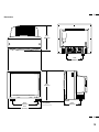
2. Part Names and Functions
Front View / Rear View ............................................................................................................. 3
Terminal Board ........................................................................................................................... 5
Remote Control Unit ............................................................................................................... 11
Battery Installation and Replacement / Remote Control Cautions / Operating Range ................ 15
Functions of DIP SW ................................................................................................................. 17
3. Installation
Wiring Diagram ........................................................................................................................ 19
Connecting Your PC or Macintosh Computer .................................................................... 21
Connecting Your VCR or Laser Disc Player .......................................................................... 22
Connecting Your Document Camera .................................................................................. 22
Connecting Your NEC IDC Series Scan Converter .............................................................. 22
Daisy-chain Your monitors ...................................................................................................... 23
D-Sub 15 Pin RGB Signal Composition .................................................................................. 24
External Speaker Connections .............................................................................................. 25
4. Operation
Power/General Controls/Degaussing ................................................................................... 27
Using OSM Controls ................................................................................................................. 28
Direct Control Screen ............................................................................................................. 29
Accessing OSM ........................................................................................................................ 32
OSM Menus .............................................................................................................................. 32
Visual Controls Group ............................................................................................................. 32
H-position/H-width/Pin-cushion Controls Group .................................................................. 33
V-position/V-height/V-linearity Controls Group ................................................................... 33
Keystone/Tilt/Rotation/Scan Select Controls Group ........................................................... 34
RGB Controls Group ................................................................................................................ 35
OSM Location/OSM Turn Off Time Control ........................................................................... 35
Source Information .................................................................................................................. 36
Volume Control ....................................................................................................................... 36
Reset Control ........................................................................................................................... 37
OSM System Control Menu .................................................................................................... 38
PC/External Control Function ................................................................................................ 41
Command Reference ............................................................................................................ 42
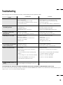
5. Troubleshooting ............................................................................................................. 45
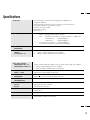
6. Specifications ................................................................................................................ 47
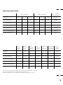
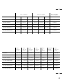
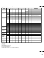
7. Timing Charts
Input Signal Reference Chart ................................................................................................ 53
Typical Input Signal Timing ..................................................................................................... 57
Signal Identification for Raster Preset .................................................................................... 61
8. Service and Support ..................................................................................................... 63
This manual covers both the XP37 Plus and the XM 37 Plus multimedia monitors. The operating
procedures are common to both models.
5
1
OSM and IPM are trademarks of NEC Technologies, Inc.
IBM PC/AT, PS/2, VGA, S-VGA, 8514/A and XGA are registered
trademarks of International Business Machines Corporation.
Apple and Macintosh are registered trademarks of Apple Computer,
Inc.
Microsoft is a registered trademark of Microsoft Corporation. Windows is
a trademark of Microsoft Corporation.
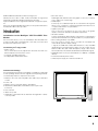
Introduction
Introduction to the MultiSync XP37 Plus/XM37 Plus
Monitor
This section introduces you to your new MultiSync XP37 Plus/XM37 Plus
monitor, provides a list of materials that comes with your monitor and
describes the features and controls.
The features you’ll enjoy include:
•Simple controls
Let you make all necessary adjustments and selections with one
button simplicity from the remote control.
•37” CRT(35” viewable image size)
• True displayable 1024 x768 resolution
• On-screen menus
Plain English and clear instructions with graphic icons show you exactly
how to adjust your screen image.
• Flexible inputs
Connect up to four different inputs at once and switch among them
with a touch of a button to seamlessly integrate information from a
computer and VCR into one presentation.
• Signal loop-through
Lets you run up to 2 monitors from one source, which can greatly
simplify connections and reduce hardware requirements.
• Attractive cabinets
A sleek, sophisticated cabinet design complements your presentation
environment and enhances the professionalism of your presentations.
• Microsoft Plug and Play compatibility
The only monitors in their class to include this standard that
automatically optimizes display settings.
• Supports most IBM VGA, S-VGA, XGA, Macintosh or any other RGB
signals within a horizontal frequency range or 15.75 to 95 kHz (15.75 to
65 kHz for XM37 Plus) and a vertical frequency range of 40 to 120 Hz.
This includes NTSC, PAL, SECAM, and M-NTSC standard video signals.
• MultiCable allows hook up to either Macintosh or IBM-PC compatible
directly.
• Front bezel and rear panel controls
• Universal power supply from 100 Vac thru 240 Vac
Contents of the Package
The following lists all of the items included in your MultiSync multimedia
monitor package. Please save the original box and packing materials
for future transportation or shipment of this monitor.
1. MultiSync XP37 Plus (XP-3790)/XM37 Plus (XM-3760) multimedia
monitor
2. Power cord
3. Wireless remote control unit and two AA batteries
4. PC/Macintosh MultiCable (15-Pin Mini D-Sub To 15-pin D-Sub
Connector)
5. User' s manual
6. Quick set up card
7. Registration card : Please fill out and return the registration card as
soon as possible.
POWER
ON
OFF
DEGAUSS
VIDEO 1 VIDEO 2 RGB 1
POSITION / CONTROL
RGB 2
PROCEED
EXIT
SCAN
WIDTH
HEIGHT SIDE PIN NORMAL
NORMAL
BRIGHT CONTRAST MUTE VOLUME
MULTIMEDIA MONITOR
RD-346E
79644641
STANDBY
/POWER
POWER
2
6
3
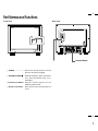
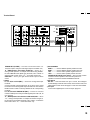
Part Names and Functions
Front View
Rear View
POWER
ON
OFF
DEGAUSS
VIDEO 1 VIDEO 2 RGB 1
POSITION / CONTROL
RGB 2
PROCEED
EXIT
SCAN
WIDTH
HEIGHT SIDE PIN NORMAL
NORMAL
BRIGHT CONTRAST MUTE VOLUME
STANDBY
/POWER
3
MULTIMEDIA MONITOR
RD-346E
POWER
2
79644641
1
VIDEO 1
VIDEO 2
RGB AUDIO
RGB 1
REMOTE EXTERNAL CONTROL
THROUGHPUT
BNC
BNC
S
IN
IN
THROUGH
OUT
THROUGH
OUT
R
S
VIDEO
1
IN
L (MONO )
RGB PROCEED
1
IN/OUT
EXIT
IN
2
THROUGH
OUT
THROUGH
OUT
HIGH
2
DIP SW
75Ω
ON
RGB 2
HIGH
75Ω
AUDIO
R
STANDBY
/POWER
75Ω
AUDIO
L (MONO )
R
IN
IN
THROUGH
OUT
THROUGH
OUT
POWER
4
R
L (MONO )
HIGH
G
B
H/CS
SPEAKER SELECT
V
INT
IN
EXT
EXT SPEAKER
L (MONO )
RIGHT
12345678
AC IN
LEFT
SPEAKRS MUST
HAVE MORE THAN
5WATT RATING
INPEDANCE 8 OHM
THROUGH
OUT
HIGH
75Ω
HIGH
75Ω
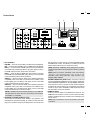
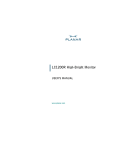
Terminal Board
1 POWER ......................... Press to turn the main power on and off
when the AC power is supplied.
2 STANDBY/POWER
... When this indicator is green, the monitor
is on; when the indicator is red, it is in
standing by.
3 Remote Sensor Window .. Receives infrared signal from the
handheld remote control.
4 Remote Control Holder .... Place remote control unit here when not
in use.
4
7
5
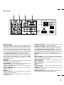
Terminal Board
6
7
VIDEO 1
VIDEO 2
RGB AUDIO
RGB 1
REMOTE EXTERNAL CONTROL
THROUGHPUT
BNC
BNC
S
S
THROUGH
OUT
IN
L (MONO )
RGB PROCEED
1
2
2
EXIT
THROUGH
OUT
THROUGH
OUT
THROUGH
OUT
VIDEO
1
IN/OUT
IN
IN
IN
R
5
HIGH
DIP SW
75Ω
ON
RGB 2
HIGH
75Ω
AUDIO
R
R
L (MONO )
HIGH
75Ω
AUDIO
L (MONO )
R
IN
IN
THROUGH
OUT
THROUGH
OUT
G
B
H/CS
SPEAKER SELECT
V
INT
IN
EXT
EXT SPEAKER
L (MONO )
RIGHT
12345678
AC IN
LEFT
SPEAKRES MUST
HAVE MORE THAN
5WATT RATING
INPEDANCE 8 OHM
THROUGH
OUT
HIGH
75Ω
5 KEY CONTROL
PROCEED.....Press to access OSM. The OSM screen is displayed.
EXIT.....Press to exit the OSM mode. The OSM screen disappears.
RGB 1/+.....Press to select an RGB video source that is connected
to the RGB 1 input terminal (D-SUB 15 pin type). When you are in
the OSM mode, this button works as the plus button.
RGB 2/-.....Press to select an RGB video source that is connected
to the RGB 2 input terminals (BNC type). When you are in the OSM
mode, this button works as the minus button.
VIDEO 1/▲.....Press to select an NTSC, PAL, SECAM or M-NTSC
compatible video source that is connected to the VIDEO 1 input
terminal (BNC type or S-VIDEO 1 IN). When you are in the OSM
mode, this button works as the up button.
VIDEO 2/▼.....Press to select an NTSC, PAL, SECAM or M-NTSC
compatible video source that is connected to the VIDEO 2 input
terminal (BNC type or S-VIDEO 2 IN). When you are in the OSM
mode, this button works as the down button.
NOTE: S-VIDEO IN terminals will take preference over VIDEO IN
terminals when the video source is connected to each terminal
and VIDEO 1 or 2 selected.
6 EXTERNAL CONTROL IN(D-Sub 15-pin)
This terminal is used when power ON/OFF, input selection, and
DEGAUSS are operated externally (by external control). See also
page 41 for external control port pin assignments. You can also use
HIGH
75Ω
this connector to connect your PC to control the MultiSync XP37
Plus/XM37 Plus monitor. This allows you to utilize your PC and
serial communication protocol to control the monitor.
NOTE: Select EXT. CONTROL ON by setting pin No. 6 of DIP
SW to the ON position when operating the monitor by external
control.
NOTE: When in the EXT. CONTROL mode, the following
operations of the supplied wireless remote control are not
possible: Power control ON/ OFF, Input selection, and
Degauss switch ON/OFF.
EXTERNAL CONTROL OUT (D-Sub 15-pin).....Connect to a second
monitor’s EXTERNAL CONTROL input to relay the signal input
at the EXTERNAL CONTROL IN. The EXTERNAL CONTROL
OUT terminal is used to connect several monitors together
and allows all of the monitors to be controlled by one external
control. No. 6 pin (EXT. CONTROL) of DIP SW must be set to
the ON position on all of the monitors.
7 REMOTE IN/OUT
Connect a remote cable to the REMOTE IN terminal. The
REMOTE OUT terminal is used to connect several monitors
together and allows all of the monitors to be controlled by one
remote control.
NOTE: Up to 50 monitors can be connected in the serial
connection.
6
8
7
Terminal Board
A
0
VIDEO 1
VIDEO 2
8
9
RGB AUDIO
RGB 1
REMOTE EXTERNAL CONTROL
THROUGHPUT
BNC
BNC
S
S
THROUGH
OUT
IN
L (MONO )
RGB PROCEED
1
2
2
EXIT
THROUGH
OUT
THROUGH
OUT
THROUGH
OUT
VIDEO
1
IN/OUT
IN
IN
IN
R
HIGH
DIP SW
75Ω
ON
RGB 2
HIGH
75Ω
AUDIO
R
R
L (MONO )
HIGH
75Ω
AUDIO
L (MONO )
R
IN
IN
THROUGH
OUT
THROUGH
OUT
G
B
H/CS
SPEAKER SELECT
V
INT
IN
EXT
EXT SPEAKER
L (MONO )
RIGHT
12345678
AC IN
LEFT
SPEAKRES MUST
HAVE MORE THAN
5WATT RATING
INPEDANCE 8 OHM
THROUGH
OUT
HIGH
75Ω
8 RGB 1 (MultiCable)
RGB Input/Throughput.....Attach either end of the MultiCable to a
computer, and then attach the other end to either of these two
connectors. You can then use the remaining connector, if you
wish, to output the computer signal to a monitor. (If you do use a
second monitor, turn the monitor switch to “on.”) Either connector
can be used for input or output, however they cannot both be
used for input simultaneously. It can damage your computer.
75 Ω/HIGH Impedance Select Switch.....This switch should be “75Ω”
for normal use without external termination or when your RGB
signal should be terminated with 75Ω. Switch to the “HIGH”
position when you have another monitor attached to your RGB
through-put connector.
9 RGB AUDIO
AUDIO R IN.....This is where you connect RGB right audio output
from a computer or another RGB source.
AUDIO L(MONO)IN.....This is where you connect RGB left audio
output from a computer or another RGB source.
AUDIO R THROUGH OUT.....Connect to a second monitor’ s
RGB right audio input.
AUDIO L THROUGH OUT.....Connect to a second monitor’s
RGB left audio input.
0 VIDEO 2
VIDEO 2 IN (BNC type).....Connect another VCR or laser disk
player here to display the video.
S-VIDEO 2 IN.....Connect S-Video input from another external
source like a VCR.
HIGH
75Ω
THROUGH OUT (BNC type).....Connect to a second monitor’ s video
input to relay the video signal input at VIDEO 2 IN.
THROUGH OUT (S-VIDEO).....Connect to a second monitor’ s Sconnector input to relay the video signal input at S-VIDEO 2 IN.
75 Ω/HIGH Impedance Select Switch for BNC type.....Set to “75 Ω”
during normal operation. In multiple connections using VIDEO 2
IN and THROUGH OUT (BNC type) terminals, set to “HIGH” on all
but the last monitor. Set to “75 Ω” on the last monitor only.
AUDIO R IN.....This is your right channel audio input for stereo
sound.
AUDIO L IN (MONO).....This is your left channel audio input for
stereo sound coming from video equipment or audio system. It
also serves as the mono audio input.
AUDIO R THROUGH OUT.....Connect to a second monitor’ s right
channel audio input.
AUDIO L THROUGH OUT.....Connect to a second monitor’ s left
channel audio input.
A VIDEO 1
VIDEO 1 IN (BNC type).....Connect a VCR or laser disk player here
to display the video.
S-VIDEO 1 IN.....Here is where you connect S-Video input from an
external source like a VCR.
THROUGH OUT (BNC type).....Connect to a second monitor’ s video
input to relay the video signal input at VIDEO 1 IN.
8
9
9
Terminal Board
VIDEO 1
VIDEO 2
RGB AUDIO
RGB 1
REMOTE EXTERNAL CONTROL
THROUGHPUT
BNC
BNC
S
S
THROUGH
OUT
L (MONO )
RGB PROCEED
1
2
2
EXIT
THROUGH
OUT
THROUGH
OUT
THROUGH
OUT
VIDEO
1
IN/OUT
IN
IN
IN
R
IN
HIGH
DIP SW
75Ω
ON
RGB 2
HIGH
75Ω
AUDIO
R
R
L (MONO )
HIGH
75Ω
AUDIO
L (MONO )
R
IN
IN
THROUGH
OUT
THROUGH
OUT
G
B
H/CS
12345678
SPEAKER SELECT
V
INT
IN
EXT
AC IN
EXT SPEAKER
L (MONO )
RIGHT
LEFT
SPEAKRES MUST
HAVE MORE THAN
5WATT RATING
INPEDANCE 8 OHM
THROUGH
OUT
HIGH
75Ω
HIGH
B
THROUGH OUT (S-VIDEO).....Connect to a second monitor’ s Sconnector input to relay the video signal input at S-VIDEO 1 IN.
75 Ω/HIGH Impedance Select Switch for BNC type.....Set to “75 Ω”
during normal operation. In multiple connections using VIDEO 1
IN and THROUGH OUT (BNC type) terminals, set to “HIGH” on
all but the last monitor. Set to “75 Ω” on the last monitor only.
AUDIO R IN.....This is your right channel audio input for stereo
sound.
B RGB 2
R, G, B, H/CS and V IN (BNC).....These are analog RGB input
terminals.
Connect external components with R, G, B, H/CS, and V output
terminals to these analog RGB input terminals. Be sure that the
RGB connection cable is correctly attached to the corresponding
terminals.
R, G, B, H/CS and V THROUGH OUT (BNC).....Connect to a second
monitor’s RGB inputs to relay the RGB signal inputs at R, G, B, H/
CS, and V IN.
75 Ω/HIGH Impedance Select Switches for RGB and H/CS&V.....Set to
“75 Ω” during normal operation. In multiple connections using R, G,
B, H/CS and V IN and OUT terminals, set to “HIGH” on all but the
last monitor. Set to “75 Ω” on the last monitor only.
75Ω
C
D
E
C EXT SPEAKER
RIGHT + ....... Connect RIGHT speaker positive wire here.
RIGHT - ........ Connect RIGHT speaker negative wire here.
LEFT - .......... Connect LEFT speaker negative wire here.
LEFT + ......... Connect LEFT speaker positive wire here.
SPEAKER SELECT INT/EXT Select Switch.....Set to the INT position
for built-in monitor speakers. Set to the EXT position for
speakers connected to the EXT SPEAKER terminals.
D DIP Switch
DIP SW..... This DIP switch sets Sync. Control, the Intelligent
Power Manager, external control on/off, remote control on/off, and
OSM system control on/off. See pages 17 and 18 for more details.
E AC Input
Connect the supplied power cord’ s three-pin plug here.
10
10
11
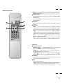
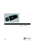
Remote Control Unit
NOTE: When not in use the remote control unit is conveniently stowed in the
holder on the rear panel.
1 POWER ON/OFF
Press POWER ON to turn the monitor on when the STANDBY/POWER
indicator is lit red.
Press POWER OFF to turn the monitor off and the monitor will go into the
standby condition.
2
POWER
OFF
ON
DEGAUSS
VIDEO 1 VIDEO 2 RGB 1
POSITION / CONTROL
Press to demagnetize the picture tube in the manual operation. See also
RGB 2
PROCEED
EXIT
4
1
2 DEGAUSS
3
5
6
page 27.
3 Input Select
VIDEO 1 ..... Press to select an NTSC, PAL, SECAM or M-NTSC
compatible video source from a VCR, laser disc player, document camera,
or an S-Video source from a VCR connected to the VIDEO 1 IN terminal.
SCAN
VIDEO 2 ..... Press to select an NTSC, PAL, SECAM or M-NTSC
compatible video source from a VCR, laser disc player, document camera,
WIDTH
HEIGHT SIDE PIN NORMAL
or an S-Video source from a VCR connected to the VIDEO 2 IN terminal.
RGB 1 ....... Press to select an RGB video source from a computer
NORMAL
BRIGHT CONTRAST MUTE VOLUME
connected to the RGB 1 IN terminal.
RGB 2 ....... Press to select an RGB video source from a computer, NEC
MULTIMEDIA MONITOR
RD-346E
scan converter or document camera connected to the RGB 2 IN terminal.
79644641
OSM Control
4 POSITION/CONTROL
) ...... Adjusts the vertical position of the image up and
POSITION(
down, and the horizontal position of the image from left to right.
CONTROL ( + / - ) ..... Moves the bar in the + or - direction to increase or
decrease the adjustment in an OSM menu.
CONTROL(
/
) .. Select one of the controls in an OSM menu. Press
select a higher item in the menu; press
to
to select a lower item in the menu.
5 PROCEED
Press to access OSM. When an adjustment item is selected, a press of this
button returns to its icon selection screen.
6 EXIT
Press to exit the OSM mode.
NOTE: The direct keys such as BRIGHT, CONTRAST, WIDTH, HEIGHT,
SIDE PIN can access each control while in the OSM mode.
12
11
13
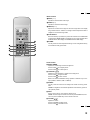
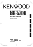
Raster Control
7 WIDTH ( + / -)
Adjusts the horizontal size of the image.
8 HEIGHT ( + / -)
Adjusts the vertical size of the image.
9 SIDE PIN ( + / -)
Adjusts the curvature of the edges of the left and right side of the display
POWER
OFF
ON
DEGAUSS
image either inward or outward. The image should be adjusted to attain a
VIDEO 1 VIDEO 2 RGB 1
POSITION / CONTROL
RGB 2
PROCEED
EXIT
9
SCAN
7
8
B
C
WIDTH
HEIGHT SIDE PIN NORMAL
NORMAL
BRIGHT CONTRAST MUTE VOLUME
MULTIMEDIA MONITOR
RD-346E
0
A
D
F
straight line on the left and right sides.
0 SCAN SELECT
Each time this key is pressed, the picture size switches from OVER SCAN
for large size to UNDER SCAN for small size and vice versa. Normally select
OVER SCAN for video display and UNDER SCAN for RGB display.
A NORMAL
This key resets the raster adjustment settings of user changeable memory
and recalls the factory preset data.
E
79644641
Visual Control
B BRIGHT ( / )
Adjusts the overall image and screen brightness.
Press and hold for a brighter picture.
Press and hold for a darker picture.
C CONTRAST ( / )
Adjusts the image brightness in relation to the background.
Press and hold for higher contrast.
Press and hold for lower contrast.
NOTE: The VISUAL CONTROL storing operation is effective only for one
input (VIDEO1, VIDEO 2, RGB 1 or RGB 2).
D NORMAL
This key resets the visual control settings and recalls the factory preset
data.
NOTE: The brightness and contrast adjustment level are factory preset at
the optimum position.
E MUTE
Press to cancel sound ; press again to restore sound.
NOTE: The other ways to restore sound are to press POWER OFF, then
ON or to press VOLUME keys on the remote control unit.
F VOLUME ( / )
Adjusts the volume.
Press and hold to increase sound.
Press and hold to decrease sound.
14
12
15
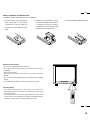
Battery Installation and Replacement
The remote control is powered by two 1.5V AA batteries.
1. Turn the remote control unit upside
down. Press down on the battery
compartment grip and slide the
compartment in the direction of the
arrow.
2. Install the two new batteries, making
sure that their polarity matches the (+)
(-) diagrams inside the battery
compartment. Incorrect polarity could
damage the remote control unit.
3. Close the battery compartment cover.
Remote Control Cautions
• Do not drop or mishandle the remote control unit.
• Do not get the remote control unit wet. If the remote gets wet, wipe it dry
immediately.
• Avoid heat and humidity.
• When not using the remote control unit for a long period, remove the
batteries.
• Do not use new and old batteries together, or use different types of batteries
together.
• Do not take apart the batteries, heat them, or throw them into a fire.
STANDBY
/POWER
POWER
Operating Range
• The infrared signal operates by line-of-sight up to a distance of
approximately 22 feet/7 m and within a 60 degree angle of the remote
sensor of the monitor.
• The monitor will not function if there are objects between the remote control
and the sensor or if strong light falls on the sensor. Weak batteries will also
prevent the remote control from properly operating the monitor.
30
30
POWER
ON
OFF
DEGAUSS
VIDEO 1 VIDEO 2 RGB 1
POSITION / CONTROL
RGB 2
PROCEED
EXIT
SCAN
WIDTH
HEIGHT SIDE PIN NORMAL
NORMAL
BRIGHT CONTRAST MUTE VOLUME
MULTIMEDIA MONITOR
RD-346E
79644641
16
13
17
Set the No. 1 pin to the ON/SHORT position when sync on green signals are
necessary for synchronization with an external component.
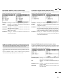
Functions of DIP SW
SHORT
ON
When a composite signal is present, the picture may be distorted. If this
happens, set the No.2 pin to the OFF/OPEN position.
1
2
3
4
5
6
7
8
OPEN
Functions and Settings of DIP SW
This DIP switch is used for Sync. Control, Intelligent Power Manager, External
control, wireless control, and OSM control. To change a switch setting use a
pointed object, such as a pen or pencil, to push the switch to the desired
position.
Set all the pins except No. 2 and 7 to the OFF/OPEN position during normal
operation.
The pins nos 3 and 5 are not used.
Pin No 1 and 2(Sync. Control )
The No. 1 and 2 pins set Sync. Control.
Set the No. 1 pin to the OFF/OPEN position and the No. 2 pin to the ON/
SHORT position during normal operation. The monitor automatically
determines if the input signal is separate sync, composite sync or sync on
green signal in this order.
Pin No. 4 (Intelligent Power Manager)
This function saves power.
When Intelligent Power Manager control is on, by using the monitor’ s
horizontal and vertical SYNC signals, the monitor can be prompted into the
different IPM modes. The following is the description of the LED indicator for
the IPM power saving modes:
Mode
On
Standby
Standby
LED Indicator
Green
Red (Steady)
Amber(Blinking quickly)
Suspend
Amber(Blinking moderately)
Off
Amber(Blinking slowly)
Power Off
No Light
Power Saving
None
None
Minimum
(Quickest recovery)
Moderate
(EPA<30 watts, Moderate recovery)
Maximum
(EPA<30 watts, Slowest recovery)
No Power Used (Fully Off)
NOTE: The Intelligent Power Manager works only for the RGB input. If
selecting the VIDEO input, or when connecting to no signal source, the
Intelligent Power Manager does not work.
Pin No. 6 (EXT. CONTROL)
When this switch is set to ON/SHORT, the External Control function is
activated. See page 41 for pin assignments. If you have some monitors you do
not want to control by remote, set to OFF/OPEN.
Pin No. 7 (REMOTE ON/OFF)
When this switch is set to ON/SHORT, the monitor can be controlled by the
wireless remote control unit.
Pin No. 8 (OSM System Control Menu ON/OFF)
When this switch is set to ON/SHORT, the system control menu is displayed.
In this menu the following features are enabled:
Power on mode set (POWER ON MODE)
Rear control key on/off (KEY CONTROL)
Language selection (LANGUAGE)
Video mode (auto/manual) selection (VIDEO MODE)
OSM on/off (OSM ON/OFF)
PC-control on/off (PC-CONTROL)
For the setting procedures to set the items, see pages 38 to 40.
18
14
19
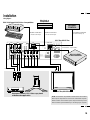
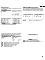
Installation
Wiring Diagram
Macintosh or
Compatibles
IBM XGA/SuperVGA/VGA or Compatibles
EXTERNAL
CONTROL
IBM/MAC MultiCable
IBM/MAC MultiCable
To D-SUB 15 Pin input
To D-SUB 15 Pin input
To EXTERNAL CONTROL
(D-SUB 15 Pin input)
XP37 Plus/XM37 Plus
VIDEO 1
VIDEO 2
RGB AUDIO
RGB 1
REMOTE EXTERNAL CONTROL
THROUGHPUT
BNC
BNC
S
S
THROUGH
OUT
IN
L (MONO )
RGB PROCEED
1
2
2
EXIT
THROUGH
OUT
THROUGH
OUT
THROUGH
OUT
VIDEO
1
IN/OUT
IN
IN
IN
R
HIGH
To R,G,B,H/CS, V inputs (BNC)
DIP SW
75Ω
ON
RGB 2
HIGH
75Ω
AUDIO
R
R
IN
THROUGH
OUT
75Ω
AUDIO
L (MONO )
IN
R
L (MONO )
HIGH
THROUGH
OUT
G
B
H/CS
SPEAKER SELECT
V
INT
IN
EXT
EXT SPEAKER
L (MONO )
RIGHT
SPEAKERS MUST
HAVE MORE THAN
5WATT RATING
INPEDANCE 8 OHM
THROUGH
OUT
HIGH
75Ω
HIGH
12345678
AC IN
NEC IDC SERIES
SCAN CONVERTER
LEFT
HIR
OYUK
AIZAS
USUS
USUS
SWA
75Ω
HIRO
YUK
AIZ
To VIDEO IN R, L, inputs
STANDBY
/POWER
POWER
XP37Plus/XM37Plus
Document camera, VCR, Video copy stand
or Multimedia application
NOTE: The two D-Sub 15-pin RGB 1 connectors here can be used to
either input or output video to or from a PC or Macintosh computer.
Either connector can be used for input or output, however they cannot
both be used for input simultaneously. It can damage your computer.
20
15
21
Connecting Your PC or Macintosh Computer
Connecting your PC or Macintosh computer to your MultiSync XP37 Plus/
XM37 Plus via the MultiCable connection system will enable you to display
your computer's screen image. All of these following display standards are
supported:
VGA 640 x 480 for graphics, VGA 640 x 400 for graphics, VGA 640 x 350 for
graphics, VGA 720 x 400 for text, VGA 720 x 350 for text, SuperVGA 800 x
600, and XGA 1024 x 768, 1280x1024 standards above 60 Hz such as Sun,
Silicon Graphics, HP, workstation standards; Macintosh at 640 x 480, 832 x
624, 1024 x 768, and 1152 x870(XP37 Plus only).
To connect to a PC, Macintosh or computer equipped with a XGA/SuperVGA/
VGA adapter or compatible graphics adapter, simply:
1. Turn off the power to your monitor and computer.
2. If your PC does not support Super XGA/VGA/VGA you will need to install
an XGA/SuperVGA/VGA graphics board. Consult your computer's owner's
manual for your XGA/SuperVGA/VGA configuration. If you need to install a
new board, see the manual that comes with your new graphics board for
installation instructions.
3. Use the supplied MultiCable to connect your computer to the monitor. For a
PC, use the smaller 15-pin connector on the cable to connect to your
computer's video port; use the larger 15-pin connector on the cable to connect to the monitor. For Macintosh, it's just the opposite. Use the larger 15pin connector on the cable to connect to your computer's video port; use the
smaller 15-pin connector on the cable to connect to the monitor. (You can
also use your own video cable if you wish. For a PC cable, use the smaller
15-pin connector on the monitor. For a Macintosh cable, use the larger 15pin connector on the monitor.)
4. Turn on the monitor and the computer.
NOTE: Refer to your computer's owner's manual for more information
about your computer's video output requirements and any special identification or configuring your monitor's image and monitor may require.
Connecting Your VCR or Laser Disc Player
Connecting Your Document Camera
Using a common RCA cable and RCA audio cables (not provided) to connect
your VCR or laser disc player to your MultiSync XP37 Plus/XM37 Plus monitor. To make these connections, simply:
1. Turn off the power to your monitor and VCR or laser disc player.
2. Connect one end of your RCA video cable to the video output connector on
the back of your VCR or laser disc player, connect the other end to the
VIDEO 1 or 2 input terminal(BNC-type) of the monitor. NOTE: You will need
an RCA to BNC adaptor (not included) to convert to the XP37Plus/
XM37Plus monitor. Use standard RCA audio patch cords to connect the
audio from your VCR or laser disc player to your monitor (if your VCR or
laser disc player has this capability). Be careful to keep your right and left
channel connections correct for stereo sound.
3. Turn on the monitor and the VCR or laser disc player.
You can connect your MultiSync XP37 Plus/XM37 Plus monitor to a document
camera. To do so, simply:
1. Turn off the power to your monitor and document camera.
2. Use a standard video cable to connect your document camera to the
VIDEO 1 or 2 input terminal(BNC-type) of the monitor.
3. Turn on the monitor and the document camera.
NOTE: Refer to your document camera's owner's manual for more
information about your camera's video output requirements .
NOTE: Refer to your VCR or laser disc player owner's manual for more
information about your equipment's video output requirements.
NOTE: S-VIDEO IN terminals will take preference over VIDEO IN terminals when a component is connected to each terminal and VIDEO 1 or 2
selected.
Connecting Your NEC IDC Series Scan Converter
You can connect an NEC IDC series scan converter to the monitor to improve
the quality of your video images. To do so:
1. Turn off the power to your monitor and scan converter.
2. Use a cable (RGB HV 5 conductor BNC/BNC) supplied with the scan
converter to connect the RGB 2 inputs of the monitor.
3. Turn on the monitor and the scan converter.
22
16
23
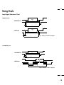
Daisy-chaining Your monitors
The REMOTE IN/OUT terminals allow you to control monitors by one remote
control.
NOTE: The connection of three XP37 Plus/XM37 Plus monitors or more with
THROUGH OUT (VIDEO 1 or 2) terminals may degrade image quality.
To do so:
When using the VIDEO inputs:
THROUGH OUT (VIDEO 1) Connections
1. Connect THROUGH OUT 1 BNC or S-VIDEO 1 OUT to external components to relay the signal input at VIDEO 1 IN(BNC-type), or S-VIDEO 1 IN.
2. Connect the external component mono audio or stereo left channel audio
input to L AUDIO.
3. Connect the external component stereo right channel audio input to R AUDIO.
4. Set the 75Ω/HIGH impedance select switch of the corresponding input signal (BNC, S-VIDEO) on all but the last monitor to “HIGH” position. On only
the last monitor is set to “75Ω” position.
THROUGH OUT (VIDEO 2) Connections
1. Connect THROUGH OUT 2 BNC or S-VIDEO 2 OUT to external component
to relay the signal input at VIDEO 2 IN(BNC-type) or S-VIDEO 2 IN.
2. Connect the external component mono audio or stereo left channel audio
input to L AUDIO.
3. Connect the external component stereo right channel audio input to R AUDIO.
4. Set the 75Ω/HIGH impedance select switch of the corresponding input signal
(BNC, S-VIDEO) on all but the last monitor to “HIGH” position. On only the
last monitor is set to the “75Ω” position.
5. Connect the REMOTE OUT of the monitor to the REMOTE IN of the next
monitor using the optional remote cable.
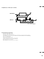
When using the RGB inputs:
THROUGH OUT Connections
1. (RGB1): Connect D-Sub 15-pin THROUGH OUT to an RGB input connector
of other monitors.
(RGB2): Connect the R.G.B.H/CS and V THROUGH OUT terminals to relay
the signal input at the R.G.B.H/CS and V IN terminals.
2. Set all the 75Ω/HIGH impedance select switches on all but the last monitor to
“HIGH” position. On only the last monitor is set to the “75Ω” position.
3. Connect the REMOTE IN of the monitor to the REMOTE OUT of the next
monitor using the optional remote cable.
NOTE: ''Plug and Play'' is available only for the monitor connected directly
to a personal computer with the D-Sub 15-pin RGB connector. Therefore,
''Plug and Play'' does not work for monitors connected with the THROUGH
OUT terminal. This is because only the RGB video, the horizontal, and the
vertical sync. signal is output from the THROUGH OUT terminals.
NOTE: ''Plug and Play'' is not available for the RGB 2 BNC terminals.
D-Sub 15 Pin RGB Signal Composition
Pin Assignments and Signal Levels for 15 pin RGB (Analog)
4 3 2 1
10 9 8 7 6
15 14 13 12 11
5
8
7
6
5
4
3
15 14 13 12 11 10
2
1
9
D-SUB 15pin RGB Input Connector (ANALOG ONLY)
Pin No.
1
2
3
12
13
14
15
4
5
6
7
8
11
10
9
Signal to be connected (D-SUB 15 pin)
RED
GREEN or Sync Green
BLUE
No Connection
H. or Composite sync
V.SYNC
No Connection
GND
GND
GND
GND
GND
GND
No Connection
No Connection
Pin No.
2
5
9
7
3
12
15
1
4
6
11
13
8
10
14
Through output (MAC 15 pin)
RED
GREEN or Sync Green
BLUE
SDA (PnP)
H. or Composite sync
V.SYNC
SCL (PnP)
GND
GND
GND
GND
GND
No Connection
No Connection
No Connection
24
17
25
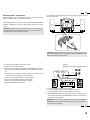
External Speaker Connections
External speakers may be connected to the monitor to reproduce sound from
VIDEO 1, VIDEO 2, RGB 1 or RGB 2 signal sources.
External speakers may be connected directly to the EXTERNAL SPEAKERS
terminals or indirectly by connecting a stereo system amplifier to the audio
outputs.
If non-shielded speakers are used, they must be located a minimum of 4 feet
away from the monitor.
SPEAKER SELECT
INT
EXT
Right
4 ft.
4 ft.
120cm
120cm
VIDEO 1
VIDEO 2
RGB AUDIO
RGB 1
REMOTE EXTERNAL CONTROL
THROUGHPUT
BNC
WARNING: Speakers that are installed next to the monitor must be
shielded against electromagnetic field which can cause color distortion in
the CRT and is not covered under the warranty.
BNC
S
R
S
RGB PROCEED
1
IN/OUT
EXIT
2
THROUGH
OUT
THROUGH
OUT
THROUGH
OUT
VIDEO
1
IN
L (MONO )
IN
IN
IN
THROUGH
OUT
HIGH
Left
2
DIP SW
75Ω
ON
RGB 2
HIGH
75Ω
R
75Ω
AUDIO
L (MONO )
R
IN
THROUGH
OUT
G
B
H/CS
SPEAKER SELECT
V
INT
IN
EXT
EXT SPEAKER
L (MONO )
RIGHT
12345678
AC IN
LEFT
SPEAKRS MUST
HAVE MORE THAN
5WATT RATING
INPEDANCE 8 OHM
THROUGH
OUT
HIGH
75Ω
HIGH
75Ω
-
|
HT
IG
R
{
+
R
L (MONO )
HIGH
AUDIO
IN
THROUGH
OUT
|-
{+
CAUTION: Unplug the monitor and all connected components before connecting external speakers. Use only speakers with 8-ohm impedance and a
power output rating of 5 watts or more.
To connect external speakers directly to the monitor:
1. Strip the ends of the speaker wires.
2. Press down a button below the EXTERNAL SPEAKERS terminals, insert
the speaker wire and release the button to secure a speaker wire connection:
[a] Connect the right speaker (located at right side of the monitor when
viewed from the front) positive (+) wire to RIGHT +.
[b] Connect the right speaker negative (-) wire to RIGHT -.
[c] Connect the left speaker negative (-) wire to LEFT -.
[d ]Connect the left speaker positive wire (+) to LEFT +.
3. Set SPEAKER SELECT switch at EXT.
VIDEO or
RGB AUDIO L and R outputs of XP37Plus/XM37Plus
R
L (MONO)
IN
LINE OR
AUX INPUT
LINE OR
AUX INPUT
L
THROUGH
OUT
R
STEREO AMP
JGHDYSTEOYII DYASGHIROYUKIAIZAWA
DFFGGGG
AFHUJTT
2Q
DFFGGGG
2Q
ZZXXC
ADFGRTRYT
AFHUJTT
2Q
HJJKKKASDFFF
ADFGRTRYT
2Q
SFGHHHJJ
CCVDFVFF
BNGGDFDFGHY
SFGHHHJJ
To connect the monitor to stereo system speakers:
1. Connect L AUDIO output to the stereo amplifier L AUX input.
2. Connect R AUDIO output to the stereo amplifier R AUX input.
3. Set SPEAKER SELECT switch at EXT to use external speakers only. For
center channel audio fill, set SPEAKER SELECT at INT for sound from both
monitor and external speakers.
IMPORTANT: Do not connect speakers to both the monitor EXTERNAL
SPEAKERS terminals and to the stereo amplifier. This could damage both
the monitor and the speakers.
26
18
27
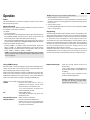
Operation
Power
This section describes how to select a computer or video source and how to
adjust the picture and sound.
General Controls
Before you turn on your MultiSync XP37 Plus/XM37 Plus monitor ensure that
the computer or video source is turned on.
1)To adjust:
1. Turn On The Monitor
The power button is on the front panel of the monitor. By turning this switch on,
the STANDBY/POWER indicator will turn to green and the monitor will
become ready to use. OSM is also usable from the rear panel.
After you press the POWER OFF button on the remote control, the monitor will
go into its standby mode and the STANDBY/POWER indicator will glow red.
2. Select The Computer Or Video Source
Press the “VIDEO 1” or “VIDEO 2” (VCR, document camera, or laser disc
player), or “RGB 1” or ” RGB 2”(computer) button on the remote control to
display the image. Or press the button on the rear panel to select your video
source: “VIDEO 1”, “VIDEO 2”, “RGB 1”, or “RGB 2”.
NOTE 1: In the U.S.A. the standard video signal format is NTSC, therefore
make sure that the AUTO or NTSC is selected on OSM system control
menu. See page 40.
Using OSM Controls
NEC's new OSM, or On-Screen Manager, System offers the ultimate form of
monitor controls. Keys on the remote control unit or rear panel allow you to
easily navigate through menus and adjust controls.
OSM controls include extended controls such as Brightness, Contrast, Size,
Position, Pin cushion, Keystone, Vertical Linearity, Scan Select and other
OSM utilities. Adjustments are saved instantly. The currently addressed
control can be reset to factory settings by pressing the NORMAL key.
OSM keys on the remote control unit function as follows:
PROCEED
: accesses the OSM controls. When an
adjustment item is selected, a press of this
button returns to its icon selection screen.
-in the color temperature: proceeds to the
control for RGB gain and bias.
EXIT
: exits the OSM controls.
-in the RGB gain and bias: return to the color
temperature screen.
POSITION CONTROL up/down : selects one of the control items.
POSITION CONTROL-/+
: increase or decrease the settings level.
: selects a group icon at top of the OSM screen
when any one of them is highlighted without
any specific control selected.
NOTE 2: Select the over scan mode for VIDEO display.
3. Adjust The Raster or The Picture Control.
You can adjust the raster such as the horizontal size, vertical size or side
pincushion correction, and the brightness and contrast of the image with the
remote control.
4. Turning Off The monitor.
Press the POWER OFF button on the remote control or press the POWER
button on the front panel.
Degaussing
The earth's magnetic field and other magnetic sources can magnetize a color
picture tube causing patches of impure colors. This monitor automatically
demagnetizes the picture tube for 5 seconds each time the monitor is switched
on. Sometimes during transportation a severe magnetic field can be
encountered which may require demagnetizing to clear the problem. Also, if
powered on for extended periods of time, magnetic fields can be produced by
the CRT itself, causing color impurities. In these cases, use the DEGAUSS
key once to demagnetize the picture tube. Pressing this key once
demagnetizes the picture tube for 5 seconds.
CAUTION: Please allow a minimum of 30 minutes to elapse between uses of
the DEGAUSS key, when not switching from mode to mode. Do not hold the
key down continuously to avoid decreasing the life of the degauss circuitry.
NORMAL (RASTER/VISUAL)
: resets the currently selected control to the
factory setting.
-when a specific group icon is highlighted, this
key resets all the specific controls settings or all
the settings.
-when a specific control is selected: this key
resets the selected adjustments.
NOTE: The NORMAL function is not valid in
the OSM Turn Off Time, Language Select
menus, and Volume Control.
28
1
29
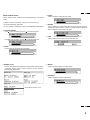
Direct Control Screen
You can adjust the raster, visual and sound using the direct key on the remote
control.
To switch to another control screen, press any one of the other keys.
*To end the OSM display, press EXIT.
*If no key operation is made within 3 seconds, the OSM display will disappear.
a. POSITION/CONTROL
Press to move the image right. Press
Press
to move the image up. Press
c. HEIGHT
Press to adjust the vertical size of the image.
d. SIDE PIN
Press to adjust the curvature of the edges of the left and right side of the
display image either inward or outward. The image should be adjusted to
attain a straight line on the left and right sides.
to move the image left.
to move the image down.
e. SCAN
Press to select the scan mode: over scan and under scan.
b. WIDTH
Press to adjust the horizontal size of the image.
f. NORMAL (raster)
Press to reset all the stored adjustment raster data and recall the factory
preset data. When a specific control is selected, this key resets the
selected raster adjustments.
g. BRIGHT
Press to adjust the brightness of video display.
h. CONTRAST
Press to adjust the contrast of video display.
Specific adjustment item to be rest
30
2
31
i. NORMAL( visual)
Press to reset all the stored adjustment visual data and recall the factory
preset data. When a specific control is selected, this key resets the selected
visual adjustments.
j. MUTE
Press to turn off the sound for a short period of time; press again to restore
the sound.
k. VOLUME
Press
to increase the sound: press
to decrease the sound.
NOTE:
When pressing a key that does not correspond to the function currently
in use, the following message will be displayed on the monitor.
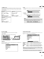
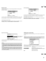
Accessing OSM
Visual Controls Group
Press the PROCEED key on the remote control or rear panel.
To turn off OSM
Press the EXIT key on the remote control or rear panel.
The visual controls allow you to adjust the picture controls such as
brightness, contrast, color, tint, and sharpness.
VIDEO
VIDEO 1 VIDEO 2 RGB 1
POSITION / CONTROL
RGB 2
RGB PROCEED
1
1
2
2
PROCEED
PROCEED
EXIT
EXIT
EXIT
OSM Menus
On-Screen Manager' s menu of Controls gives you an overview of the
selection of controls available.
BRIGHTNESS
CONTRAST
SHARPNESS
COLOR
TINT
: Pressing + or - increases or decreases the image brightness level.
: Pressing + or - increases or decreases the image contrast level.
: Pressing + or - increases or decreases the image sharpness level.
: Pressing + or - increases or decreases the image color saturation level
: Pressing + or - increases or decreases the red and green values.
NOTE: The color, tint and sharpness controls are not available for RGB
input, and the tint is not available for PAL input.
NOTE: Pressing the visual NORMAL key resets all the visual controls to the
factory settings when only the visual controls group icon is highlighted.
32
3
33
H-position/H-width/Pin-cushion Controls Group
V-position/V-height/V-linearity Controls Group
The H-position/H-width/Pin-cushion Controls allow you to adjust the horizontal
position, horizontal size and pin-cushion of the image.
The V-position/V-height/V-linearity Controls allow you to adjust the vertical
position, vertical size and vertical linearity of the image.
H-POSITION
H-WIDTH
V-POSITION
V-HEIGHT
: Pressing + or - moves the image horizontally right or left.
: Pressing + or - decreases or increases the horizontal size of
the image (wider or narrower).
PIN-CUSHION : Pressing + or - decreases or increases the curvature of the
sides either inward or outward.
PIN-BALANCE : Pressing + or - decreases or increases the curvature of the
sides to right or to left.
PIN-CORNER : Pressing + or - decreases or increases the curvature of the four
corners inward outward.
NOTE: The V-LINEARITY controls allow you to adjust the spacing of the
areas on the screen. The object of this control is to ensure that a one-inch
circle is a true one-inch circle where ever it is drawn on the screen.
: Pressing + or - moves the image vertically up or down.
: Pressing + or - increases or decreases the vertical size of the
image (taller or shorter).
V-LINEARITY 1 : Pressing + increases the spacing between the lines near the
top and decreases the lines near the bottom at the same time;
pressing - increases the spacing between the lines near the
bottom and decreases the lines near the top at the same time.
V-LINEARITY 2 : Pressing + or - increases or decreases the spacing between
the lines near the top of your screen and near the bottom of
your screen at the same time.
Keystone/Tilt/Rotation/Scan Select Controls Group
The Keystone/Tilt/Rotation/Scan Select Controls allow you to adjust the raster
rotation or angle of the sides of your display and to select either Under Scan
(for RGB display) or Over Scan (for VIDEO display).
• draw equally spaced horizontal lines using a drawing application that has a
ruler.
•use the V-LINEARITY 1 and 2 controls to adjust the spacing between
the lines near the top and the bottom of your screen.
KEYSTONE (trapezoidal) : Pressing + or - increases or decreases the bottom of
the screen to be the same as the top.
TILT
: Pressing + or - increases or decreases the tilt of your
display.
ROTATION (raster rotation) : Pressing + or - rotates the entire display clockwise or
counter clockwise.
SCAN SELECT
: Pressing + or - selects the over scan mode or the
under scan mode.
34
4
35
RGB Controls Group
OSM Location/OSM Turn Off Time Control
The RGB Controls allow you to adjust the color temperature and the white
balance for RGB input.
You can choose where you would like OSM image to appear on your screen.
Selecting OSM location allows you to manually adjust the OSM menu left, right,
up, or down. The OSM menu will stay on as long as it is in use. In the OSM Turn
Off Time submenu, you can select how long the monitor waits after the last
touch of a key to shut off the OSM menu. The preset choices are 5, 10, 30, and
120 seconds. Note that 30 seconds is the factory preset.
COLOR TEMP.
: Pressing + selects the color temperature: 10500 K, 9300K,
6500K or custom.
OSM H-POSI
: Pressing + or - moves the OSM menu right or left.
OSM V-POSI
: Pressing + or - moves menu up or down.
OSM TURN OFF TIME : Pressing + or - selects the preset time in increasing or
Pressing the PROCEED key proceeds to the RGB gain and bias adjustment.
This adjustment allows you to adjust the white balance.
R, G, B-GAIN
R, G, B-BIAS
: Pressing + or - increases or decreases the gain level for each color.
: Pressing + or - increases or decreases the bias level for each color.
Source Information
Volume Control
Source Information provides you information about the current resolution
display and technical data including the horizontal and vertical frequency.
The Volume control allows you to adjust the volume.
NOTE: These adjustments are for RGB mode only.
VOLUME : Pressing + or - increases or decreases the volume.
NOTE: When you mutes the sound, the MUTE display appears.
H-FREQ
V-FREQ
H-POL
V-POL
NEG
POS
:
:
:
:
:
:
indicates the horizontal frequency of the current input signal.
indicates the vertical frequency of the current input signal.
indicates the polarity of the horizontal sync. signal.
indicates the polarity of the vertical sync. signal.
indicates the polarity is negative.
indicates the polarity is positive.
36
5
37
All Visual Settings
Reset Control
The Reset control allows you to return image parameters to factory presets.
All Raster Settings
The above warning statement will appear to confirm that you do want to reset
all raster settings. If you want to reset all raster settings, press PROCEED.
The above warning statement will appear to confirm that you do want to reset all
visual settings. If you want to reset all visual settings, press PROCEED.
The following items can be reset:
BRIGHTNESS, CONTRAST, COLOR, TINT, SHARPNESS, COLOR TEMP.,
R-GAIN, G-GAIN, B-GAIN, R-BIAS, G-BIAS, and B-BIAS.
The following items can be reset:
H-POSI, H-WIDTH, PIN-CUSHION, PIN-BALANCE, PIN-CORNER, V-POSI,
V-HEIGHT, V-LIN1, V-LIN2, KEYSTONE, TILT and ROTATION.
Specific Item Settings
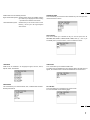
OSM System Control Menu
The OSM System control menu allows you to set a various conditions of the
monitor.
Specific adjustment
item to be reset.
NOTE: This control is available only when No. 8 pin of the DIP switch is set at
the ON position. The DIP switch is located on the back cabinet.
The above warning statement will appear to confirm that you do want to reset
individual settings.
NOTE:
• In addition to OSM controls, adjustments can be directly accessed with the
remote control keys. When adjusting with the remote control keys, the onscreen display for the related adjustment appears instead of the OSM
menu.
• When OSM ON/OFF is set at OFF in the System Control menu(see the
following section ), OSM controls are not available while the remote control
direct access is possible.
OSM keys on the remote control unit function as follows:
POSITION CONTROL up/down : highlights one of the control items in the System
control menus.
POSITION CONTROL +
: proceeds to the selected menu choice.
POSITION CONTROL : exits the current control and returns to its original
System control menus.
EXIT
: exits the OSM controls.
38
6
39
OSM windows have the following elements:
Right-oriented delta symbol : indicates further choices are available. Use the
up or down keys to highlight the item. Pressing
+ proceeds to the selected control screen.
Left-oriented delta symbol : indicates that you can exit the current control.
Pressing - returns you to its original System
control menus.
POWER ON MODE
This control allows you to set the monitor to default to any one of its inputs each
time the monitor is turned on.
KEY CONTROL
This control allows you to disable the keys on the rear panel such as
PROCEED, EXIT, VIDEO 1, VIDEO 2, RGB 1, RGB 2, down, up, -, and +. If you
accidentally hit any one of the buttons, it does not affect the monitor.
KEY
LANGUAGE
OSM menus are available in six languages: English, German, French,
Spanish, Italian, and Swedish.
VIDEO MODE
This control allows you to select the NTSC, PAL, or SECAM video standard.
Normally select AUTO.
OSM ON/OFF
This control allows you to enable the OSM control.
The OSM control is available when ON is selected. When the OSM does not
appear, the visual and raster controls are available with the remote control.
PC-CONTROL
This control allows you to activate the PC-control function.
For more information see the following pages.
40
7
41
PC/External Control Function
4 3 2 1
10 9 8 7 6
15 14 13 12 11
5
PC/External Control Port Pin Assignments
D-SUB 15pin (Input/Output)
Pin No.
1
6
2
7
11
12
3
8
9
4
5
10
13
14
15
Signal Name
No Connection
Receive Data
No Connection
Transimit Data
No Connection
Clear to Send
No Connection
Request to Send
Ground
Input Select
Input Select
Power ON/OFF
No Connection
Degauss ON/OFF
Signal Ground
NOTE: If EXT.CTL is set to ON, only EXT.CTL will be effective for the
functions :Input selection, Power ON/OFF and Degauss ON/OFF.
If EXT.CTL is set to OFF, PC CTL will be effective. Pin No.8 is
connected to pin No. 12.
External Control
Pin No.
EXT-CTL
EXT-CTL
EXT-CTL
EXT-CTL
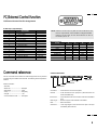
Command reference
You can control the main functions from external equipment such as personal
computer using the PC/EXT CTL terminals. The following sections explain the
interface.
Interface Condition
• RS-232C
• Baud rate ------------------------- 9600 bps
• Data length ----------------------- 8 bits
• Parity ------------------------------- Odd parity
• Stop bit ---------------------------- 1 bit
• Communications mode -------- Full duplex
VIDEO1
VIDEO2
RGB1
RGB2
POWER OFF
POWER ON
DEGAUSS OFF
DEGAUSS ON
4
OPEN
GND
OPEN
GND
-
5
OPEN
OPEN
GND
GND
-
-
-
10
-
14
-
OPEN
GND
-
OPEN
GND
Control Data Format
8bit
8bit
8bit
8bit
8bit
8bit
8bit
Data
Data length
Command 2
UNIT ID
Command 1
8bit
Check Sun
Command 1 ........ Code based on the command system
UNIT ID ............... Code allocated to each equipment (Allocate 80H to the
XP37 Plus/XM37 Plus)
Command 2 ......... Code allocated to the main functions of the XP37 Plus/XM37
Plus
Data Length ........ Number of bytes of the data that is transmitted
Data .................... Data transmitted
Check Sum ......... Lower eight digits of sum total of the first byte to the byte
immediately before the last.
42
8
43
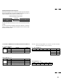
Command Communication Sequence
When external equipment such as a personal computer gives the command to
the XP37 Plus/XM37 Plus, the XP37 Plus/XM37 Plus returns an ACK. So
make sure that the external equipment receives this ACK.
Command sending/receiving sequence
Command
External equipment
(PC)
XP37 Plus/XM37 Plus
ACK
The XP37 Plus/XM37 Plus returns an ACK if it has received the command
correctly.
If it has not received the command correctly due to data error, it will return
nothing. Therefore, when the external equipment send a command, make
sure that it received the ACK.
PC CONTROL COMMAND LIST FOR USE WITH THE XP37 Plus/XM37 Plus
PC → XP37 Plus/XM37 Plus
COM2
COM1
4E
9F
4F
A1
Contents
Power On
Power Off
Degauss Control
Length
00
00
00
Example: Input switching (VIDEO 1) from the PC to the XP37 Plus/XM37
Plus(when the address selector equals 0)
PC → XP37 Plus/XM37 Plus
COM1
DF
UA
COM2
Length
80
B0
02
Data 1
00
Data 2
VIDEO1 : 01
VIDEO2 : 02
RGB1 : 03
RGB2
XP37 Plus/XM37 Plus → PC
COM1
COM2
3F
4E
4F
B0
7F
A1
Contents
Power On (ACK)
Power Off (ACK)
Input Switching (ACK)
Degauss Control(ACK)
Length
00
00
00
01
: 04
Sum
12
13
14
15
XP37 Plus/XM37 Plus → PC
COM1
3F
UA
80
COM2
B0
Length
00
Data 1
6F
44
9
45
Troubleshooting
Before arranging for service by the NEC Service Center, check the following to be sure repairs are needed.
Possible Cause
Problem
No Picture or Sound
Power cord unplugged.
Plug in power cord.
Power outlet inactive.
Be sure wall switch is on and outlet has power.
Switch to ON or connect to an active AC outlet.
Power of external equipment is not ON.
External equipment has been incorrectly connected.
Sound OK; poor picture
with VIDEO signal input.
Correction
Correct all connections.
Incorrect input selection.
Press correct RGB1, RGB 2, VIDEO 1 or VIDEO 2 button.
Improper control setting.
Adjust picture controls as needed.
Try another location for the monitor.
Local interference.
Cable interconnections.
Be sure all connections are secure.
Input impedance is not correct level.
Check 75 ohm high impedance select switch.
Sound OK; poor picture with
RGB signal input.
Improper control setting.
Incorrect 15 PIN connector pin connections.
Adjust picture controls as needed.
Check pin assignments and connections.
Picture OK; poor or no sound.
Cable interconnections.
Volume is not adjusted.
Be sure all connections are secure.
Adjust volume.
Poor audio connections from external source.
Correct audio connections.
Adjust volume controls.
Improper control settings.
MUTE key is ON.
Press again to restore sound.
Poor sound from external speakers
Cable interconnections.
Secure all cable connections.
or stereo system speakers
Improper volume setting.
Check volume controls of all components.
Remote control does not work.
Weak batteries.
Install new batteries.
Obstacle between Remote Control and Sensor
Point remote control directly at Sensor Window.
Window. (Wireless)
You are not within the effective operating range.
Use the remote control unit within 30° left and right
(Wireless)
of center (at a distance of within 22ft).
Incorrect setting of No. 7 pin of the DIP SW. (Wireless)
Set Pin no. 7 of DIP SW to ON/SHORT.
When in the EXT. CONTROL mode, the remote
Set Pin no.6 of DIP SW to OFF/OPEN.
control unit will not operate the monitor.
STANDBY/POWER indicator is
Horizontal and/or vertical sync signal is not present
blinking
when the Intelligent Power Manager control is on.
Check the input signal.
In the following case, power off the monitor immediately and contact your dealer or authorized NEC Service Center.
The monitor turns off in 5 seconds after powering on and then the STANDBY/POWER indicator blinks in one second intervals. It indicates that the power
supply circuit or, one or more fans have been damaged.
46
10
47
Specifications
Picture tube
35 inch Visual size; 37 inch CRT size (Diagonal), Type M89LAK113K
108 degree deflection
Stripe trio pitch Ph 0.85 mm at center, Ph 1.05 mm at corner/Pv 0.87 mm
Invar mask, Medium-short persistence phosphor
Anti-static electricity coating
Optical filter coating
Dynamic focus
RGB Input Terminals
RGB 1 :
:
:
:
:
D-SUB 15pin/mini D-SUB 15pin RGB 2: (R, G, B, H/CS and V)
Video : Analog 0.7Vp-p/75 Ohms (Positive)
Sync. : Separate Sync. TTL level, 0.7 - 4.0Vp-p/75 Ohms..........RGB 2 only
Horizontal Sync.
(Positive/Negative)
Vertical Sync.
(Positive/Negative)
Composite Sync. TTL Level
(Positive/Negative)
Composite Sync. On Green Video 0.3Vp-p (Negative)
RGB Output Terminals
THROUGH OUT
RGB 1 : D-SUB 15 pin/mini D-SUB 15 pin
Video Input Terminals
VIDEO 1/2
S-VIDEO (Video 1/2)
1.0Vp-p, 75 Ohms unbalanced (BNC-Jack), Composite video signal, Sync-negative.
Y
: 1.0Vp-p, 75 Ohms unbalanced, Sync-negative.
C : 0.28Vp-p, 75 Ohms unbalanced, Color burst level.
Video Output Terminals
THROUGH OUT (Video 1, 2)
THROUGH OUT (S-VIDEO 1, 2)
RGB 2 : BNC (R, G, B, H/CS and V)
1.0Vp-p, 75 Ohms unbalanced (BNC Jack), Composite video signal, Sync-negative.
Y : 1.0Vp-p, 75 Ohms unbalanced, Sync-negative.
C : 0.28Vp-p, 75 Ohms unbalanced, Color burst level.
Audio Input Terminals
VIDEO 1, 2 / RGB
Left (Mono) : 0.5 Vrms, high impedance (Pin-Jack)
Right : 0.5Vrms, high impedance (Pin-Jack)
Audio Output Terminals
THROUGH OUT
Left : 0.5 + 0.1 Vrms, less than 22 K Ohms (Pin-Jack)
Right : 0.5 + 0.1 Vrms, less than 22 K Ohms (Pin-Jack)
External Control
(IN/THROUGH OUT)
mini D-SUB 15pin (IN/THROUGH OUT)
SOUND Output
Internal
External
2.5W+2.5W (THD 10%) at 16 Ohm
5W+5W (THD10%) at 8 Ohm
Speaker
Oval type 9 X 5.5 cm
16 Ohm, 2pcs.
Display Colors
Analog Input: Unlimited colors
Synchronization Range
Horizontal: XP37Plus; 15.7/31 KHz to 95 KH XM37Plus; 15.7/31 KHz to 65 KHz (Automatically)
Vertical:40 Hz to 120 Hz (Automatically)
48
11
49
Maximum Resolution
RGB 1024( H) X 768(V) pixels
VIDEO Horizontal: 500 lines /S-VIDEO Horizontal : 600 lines
Video Bandwidth
RGB: 70 MHz at-3dB
VIDEO: 5 MHz at-3dB
Display Area
RGB : 95% Scan (Typically)
VIDEO: 7% Overscan
Retrace Time
Horizontal: 15.75kHz: 7.0µsec, 30kHz<fH<50kHz:3.3µsec,
51kHz<fH<80kHz:2.9µsec, 81kHz<fH<95kHz:2.7µsec
Vertical: 0.4 msec
Current Rating
AC 100-120 V/220-240 V, 50/60 Hz
Power Consumption
XP37 Plus(XP-3790): 4.5 A (maximum) / XM37 Plus(XM-3760): 4.5A (maximum)
Dimensions
872(W) x 744(H) x 590(D) mm / 34.4(W) x 29.3(H) x 23.3(D) inches
Weight
103.5 kg / 228.2 lbs
Environmental Considerations
Operating Temperature
Humidity
Altitude
Storage Temperature
Humidity
Altitude
Regulations :
UL Approved (UL 1950, CSA 950)
Meets DOC Canada requirements
Meets FCC class A requirements
Meets DHHS requirements
Meets RED ACT
:
:
:
:
:
:
0 to 40
0 to 90%
0 to 10,000 feet
-10 to 50
0 to 95%
0 to 45,000 feet
All specifications are subject to change without notice.
50
12
51
Dimensions
23.3''
(590mm)
VIDEO 1
VIDEO 2
RGB AUDIO
RGB 1
REMOTE EXTERNAL CONTROL
THROUGHPUT
BNC
BNC
S
IN
IN
THROUGH
OUT
THROUGH
OUT
R
S
VIDEO
1
IN
L (MONO )
RGB PROCEED
1
IN/OUT
EXIT
IN
2
THROUGH
OUT
THROUGH
OUT
HIGH
2
DIP SW
75Ω
ON
RGB 2
HIGH
75Ω
AUDIO
R
R
L (MONO )
HIGH
75Ω
AUDIO
L (MONO )
R
IN
IN
THROUGH
OUT
THROUGH
OUT
G
B
H/CS
SPEAKER SELECT
V
INT
IN
EXT
EXT SPEAKER
L (MONO )
RIGHT
12345678
AC IN
LEFT
SPEAKRS MUST
HAVE MORE THAN
5WATT RATING
INPEDANCE 8 OHM
THROUGH
OUT
HIGH
75Ω
HIGH
75Ω
15.8''
(400mm)
29.3''
(744mm)
25.6''
(650mm)
34.4''
(872mm)
3.6''(90mm)
16.8''
(425mm)
52
13
53
Timing Charts
Input Signal Reference Chart
Separate Sync.
VIDEO
D
C
HORIZONTAL
E
B
A
VIDEO
VERTICAL
Q
R
S
P
Sync. Polarity: Positive / Negative
O
Composite Sync.
VIDEO
HORIZONTAL
D
C
E
B
A
VIDEO
Q
VERTICAL
R
S
P
O
Sync. Polarity: Positive / Negative
54
14
55
Composite Sync. & Video (Sync. on Green)
VIDEO
HORIZONTAL
B
E
D
C
A
VIDEO
VERTICAL
P
P
R
Q
S
O
Sync. Polarity: Negative
Recommended Sync Signal Timing
Horizontal sync duty should be 3 to 30%.
Horizontal sync width should exceed 0.9 µsec.
Horizontal back porch should exceed 2.0 µsec at sync on green and 1.2 µsec at others except when at 15KHz.
Horizontal blanking should exceed: 7.0µse at fH 15.75kHz, 3.3µsec at 30 kHz<fH<50kHz, 2.9µusec at 51kHz<fH<80kHz,
and 2.7µsec at 81kHz<fH<95kHz
Vertical sync duty should be 0.2 to 10%.
Vertical sync width should exceed 40 µsec or 2 horizontal lines.
Vertical sync width plus back porch should exceed 0.4 msec.
Interlaced signals are not recommended.
Interlaced signals with composite sync may not be displayed.
56
15
57
Typical Input Signal Timing
VGA Compatible
Resolution
Mac U , Quadra,
or LC Compatible
XGA-2 Compatible
640~ 350
720~ 400
640~ 480
720~ 350
720~ 400
640~ 480
640~ 480
Horizontal Frequency
31.469KHz
31.469KHz
31.469KHz
39.444KHz
39.444KHz
39.375KHz
35.000KHz
(A) Horizontal Period
31.778µsec
31.778µsec
31.778µsec
25.352µsec
25.352µsec
25.397µsec
28.570µsec
(B) Horizontal Pulse Width
3.813µsec
3.813µsec
3.813µsec
3.042µsec
3.042µsec
3.048µsec
2.120µsec
(C) Horizontal Back Porch
1.589µsec
1.589µsec
1.589µsec
1.522µsec
1.522µsec
1.524µsec
3.170µsec
(D) Horizontal Active Area
26.058µsec
26.058µsec
26.058µsec
20.282µsec
20.282µsec
20.317µsec
22.810µsec
0.318µsec
0.318µsec
0.318µsec
0.508µsec
0.508µsec
0.508µsec
0.180µsec
VESA
640~ 480
at 72Hz
VESA
800~ 600
at 56Hz
(E) Hrizontal Front Porch
Resolution
VESA
800~ 600
at 60Hz
VESA
800~ 600
at 72Hz
MAC U
&
Quadra
8514/A & XGA
Interlaced
Compartible
VESA
1024~ 768
at 60Hz
640~ 480
800~ 600
800~ 600
800~ 600
832~ 624
1024~ 768
Horizontal Frequency
37.860KHz
35.156KHz
37.879KHz
48.077KHz
49.725KHz
35.587KHz
48.363KHz
(A) Horizontal Period
26.413µsec
28.444µsec
26.400µsec
20.800µsec
20.111µsec
28.100µsec
20.677µsec
(B) Horizontal Pulse Width
1.270µsec
2.000µsec
3.200µsec
2.400µsec
1.117µsec
3.910µsec
2.092µsec
(C) Horizontal Back Porch
4.063µsec
3.556µsec
2.200µsec
1.280µsec
3.910µsec
1.247µsec
2.462µsec
(D) Horizontal Active Area
20.317µsec
22.222µsec
20.000µsec
16.000µsec
14.524µsec
22.760µsec
15.754µsec
(E) Horizontal Front Porch
0.762µsec
0.667µsec
1.000µsec
1.120µsec
0.559µsec
0.178µsec
0.369µsec
1024~ 768
*VGA, XGA, XGA-2, and 8514/A are the trademarks of International Business Machines Corporation.
*Macintosh II, Quadra, and LC are the trademarks of Apple Computer Inc.
*VESA is the trademark of a non-profit organization, Video Electronics Standards Association.
58
16
59
VGA Compatible
Resolution
640~ 350
720~ 400
Mac U , Quadra,
or LC Compatible
XGA-2 Compatible
640~ 480
720~ 400
720~ 350
640~ 480
640~ 480
Vertical Frequency
70.080Hz
70.080Hz
59.940Hz
87.850Hz
87.850Hz
75.000Hz
66.667Hz
(O) Vertical Period
14.268msec
14.268msec
16.683msec
11.383msec
11.383msec
13.333msec
15.000msec
(P) Vertical Pulse Width
0.064msec
0.064msec
0.064msec
0.051msec
0.051msec
0.051msec
0.090msec
(Q) Vertical Back Porch
1.716msec
0.890msec
0.793msec
1.496msec
0.862msec
0.813msec
1.110msec
(R) Vertical Active Area
11.504msec
13.156msec
15.762msec
8.873msec
10.141msec
12.190msec
13.710msec
(S) Vertical Front Porch
0.985msec
0.159msec
0.064msec
0.963msec
0.329msec
0.279msec
0.090msec
VESA
640~ 480
at 72Hz
Resolution
640~ 480
VESA
800~ 600
at 56Hz
800~ 600
VESA
800~ 600
at 60Hz
VESA
800~ 600
at 72Hz
MAC U
&
Quadra
800~ 600
800~ 600
832~ 624
8514/A & XGA
Interlaced
Compartible
VESA
1024~ 768
at 60Hz
1024~ 768
1024~ 768
Vertical Frequency
72.809Hz
56.250Hz
60.317Hz
72.187Hz
74.550Hz
86.960Hz
60.000Hz
(O) Vertical Period
13.735msec
17.778msec
16.579msec
13.853msec
13.414msec
11.499msec
16.667msec
(P) Vertical Pulse Width
0.079msec
0.057msec
0.106msec
0.125msec
0.060msec
0.112msec
0.124msec
(Q) Vertical Back Porch
0.740msec
0.626msec
0.607msec
0.478msec
0.784msec
0.577/0.563msec
0.600msec
(R) Vertical Active Area
12.678msec
17.067msec
15.840msec
12.480msec
12.549msec
10.824msec
15.880msec
(S) Vertical Front Porch
0.238msec
0.028msec
0.026msec
0.770msec
0.020msec
0.000/0.014msec
0.062msec
60
17
61
Signal Identification for Raster Preset
MODE
MODE1
Polarity
Hor
Ver
-
State
Hor
-
-
Ver
-
Frequency
Hor
Ver
-
-
NEC
USER
PRESET PRESET
YES-1
15.5-16.0KHz
MODE2
30-33KHZ
REMARKS
YES-1
NTSC
YES-2
RGB 15kHz
YES-2
YES-3
PAL/SECAM
-
-
-
YES-3
YES-4
VESA I-Standard 640x480(31.5KHz/60Hz)
-
-
-
-
-
YES-4
-
(H)
H
-
-
-
YES-5
IBM 640x350(31.5KHz/71Hz)
NEG
NEG
-(H)
POS
POS
POS
NEG
NEG
POS
(H)
H
-
-
-
YES-6
IBM 640x400(31.5KHz/71Hz)
MODE3
NEG
(NEG)
(H)
H
-
-
-
YES-7
HDTV(33.75KHz/60Hz)
33-37KHZ
POS
NEG
(H)
H
-
POS
POS
(H)
H
-
-
-
-
L
-
NEG
(NEG)
(H)
H
-
-
POS
NEG
(H)
H
-
-
-
POS
POS
(H)
H
-
-
-
-
-
L
-
-
NEG
(NEG)
(H)
H
-
POS
NEG
(H)
H
-
POS
POS
(H)
H
-
-
MODE4
37-43KHz
MODE5
43-49KHz
MODE6
49-54KHz
-
-
-
YES-7
-
YES-4
YES-8
VESA 800x600 (35.1KHz/56Hz)
60 or greater
-
YES-9
VESA I-Standard 1024x768 (35.5KHz/87Hz)
-
YES-5
YES-10
MAC 640x480(35KHz/67Hz)
YES-11
VESA 640x480(37.5KHz/75Hz)
YES-11
-
YES-6
YES-12
VESA 800x600(37.9KHz/60Hz)
-
YES-13
REUTER 640x480(38.4KHz/72Hz)
-
YES-7
YES-14
VESA 1024x768 (48.4kHz/60Hz)
-
-
YES-14
-
-
-
-
YES-15
VESA 800x600 (46.9KHz/75Hz)
L
-
-
-
YES-16
REUTER 800x600 (48.1KHz/72Hz)
60 or less
(NEG)
(NEG)
(H)
H
-
-
-
YES-17
H-98 1120x750 (50.0KHz/60.1Hz)
-
-
-
L
-
-
YES-8
YES-18
MAC 832x624 (49.7KHz/75Hz)
-
YES-9
YES-19
VESA 1024x768 (56.5KHz/70Hz)
(NEG)
(NEG)
(H)
(H)
-
MODE8
(POS)
(POS)
(H)
H
-
-
YES-10
YES-20
VESA 1024x768 (60.0KHz/75Hz)
58-64KHz
-
-
-
L
-
-
-
YES-21
MAC 1024x768 (60.2KHz/75Hz)
H
-
-
YES-11
YES-22
VESA 1280x1024 (64.6KHz/60Hz)
L
-
-
-
YES-23
MAC 1152x870 (68.7KHz/75Hz)
-
YES-12
YES-24
VESA 1280x1024 (80.0KHz/75Hz)
-
YES-13
YES-25
VESA 1600x1200 (93.8KHz/75Hz)
MODE7
54-58KHz
MODE9
(NEG)
(NEG)
64-74KHz
-
-
MODE10
(H)
-
(POS)
(POS)
(H)
(H)
-
(POS)
(POS)
(H)
(H)
-
74-85KHz
MODE11
85-95KHz
NOTE:
L=NEG.SYNC
H=POS.SYNC
"-" or "()" =ignored
Factory:13 (10 preset for XM37 Plus)
User:25 (22 preset for XM37 Plus)
The modes 9(MAC 1152x870), 10, and 11 apply to XP37 Plus only.
62
18
63
Service and Support Policies
NEC Technologies is committed to providing the highest quality service
and support for your MultiSync presentation monitor. A customer
service group that is dedicated to the support of this product line is
available to provide a single point of contact for technical support,
trouble shooting, service and repair issues.
Please address all questions concerning the following subjects to the
phone number listed below:
For technical support or any questions concerning the
operation of this product.
To arrange for on-site repair service during the warranty period
or after its expiration.
For the location of your nearest authorized NEC service center.
To report a DOA product and verify its status for return
authorization.
1-800-836-0655
Due to the size and weight of large screen presentation monitor
products, it is preferable to solve problems on-site rather than to incur
the expense and risk of damage in return shipping. NECís service
policies and procedures make it as effortless as possible for you to
receive factory authorized and trained service at your location.
Eligibility/Return for Exchange Procedure
If a product is suspected of being DOA, customers must call NECTECH
VSD Technical Support. A representative will assist in making the
product fully functional or verify it as a DOA.
VSD Technical Support 1-800-836-0655
NEC technical support will provide a procedure for repair instead of
exchange.
On-site Service/Repair Policy
NEC offers on-site service and repair for all of our MultiSync presentation
monitor products of 37" and larger screen size. Warranty repair is
provided by our service-authorized Visual Systems Division Dealers and
network of factory-trained independent service providers. If you are
experiencing a problem with your monitor, please contact the
authorized NEC Visual Systems Division dealer from which it was
purchased. If this is a reseller who is unable to provide service, call NEC
directly at 1-800-836-0655.
DOA Policy
A product is considered DOA if it fails to function according to current
published specifications because of defects in NECTECH factory
materials and/or workmanship during the first 30 days from the date of
purchase by the end user. After the 30 day period any defective
product will be considered a warranty repair.
A product is NOT considered DOA if it is functional but the box is
damaged or it is missing contents such as manuals, cables, etc.
NECTECH reserves the right to repair rather than replace any
product.
Any questions concerning service and repair policies or procedures
can also be addressed in writing to:
NEC Technologies
Visual Systems Division
Customer Service
1250 North Arlington Heights Road
Itasca, Illinois 60143
If the product is determined to be DOA, the Technical Support
Representative will request the following information in order to issue a
Material Return Authorization (MRA) number:
Product model number
Serial number
A complete description of the problem
If approved, an MRA number and return address will be issued. All
product to be returned must be shipped freight pre-paid in its original
carton to a designated NECTECH facility. The customer assumes the
risk of loss. The defective product must be received by NECTECH within
21 calendar days from the date the MRA was issued.
64
19
20