1
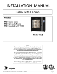
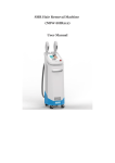
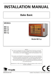
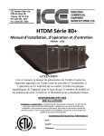
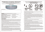
POOL HEAT PUMP UNIT SHP48 Chlorine or Salt Pools Inground / Aboveground Indoor /Outdoor Installation & Instruction Manual CONTENTS 1. Preface 2. Specifications 2.1 Performance Data of Swimming Pool Heat Pump Unit 2.2 Dimensions for Swimming Pool Heat Pump Unit 3. Installation and Connection 3.1 Installation of System 3.2 Swimming Pool Heat Pump Location 3.3 How Close to Your Pool? 3.4 Swimming Pool Heat Pump Plumbing 3.5 Swimming Pool Heat Pump Electrical Wiring 3.6 Initial Start-up of the Unit 4. Usage and Operation 4.1 Function of controller 4.2 The controller usage 4.3 Parameter table 5. Maintenance and Inspection 5.1 Maintenance 5.2 Trouble Shooting Guide 5.3 Connection of PCB illustration 5.4 Connection of PCB illustration 6. Appendix 6.1 Cautions & Warnings 6.2 Cable specification 1. PREFACE In order to provide our customers with quality, reliability and versatility, this product has been made to strict production standards. This manual includes all the necessary information about installation, trouble shooting, and maintenance. Please read this manual carefully before you install the unit. The manufacturer of this product will not be held responsible if someone is injured or the unit is damaged as a result of improper installation or poor maintenance. These instructions should be followed carefully. The unit must be installed by qualified personnel. The unit can only be repaired by qualified personnel or an authorized dealer. Maintenance and operation must be carried out according to the recommended time and frequency, as stated in this manual. Use genuine standard spare parts only. Failure to comply with these recommendations will invalidate the warranty. The Pool Heat Pump Unit heats the swimming pool water and keeps the temperature constant. The heat pump has the following characteristics: Flexibility – Heating & Cooling This unit provides both heating and cooling of a pool or other large water supply. It can maintain a consistent temperature automatically. Solar-Ready This unit it designed to operate on solar panels when configured per HotSpot Energy solar heat pump pool heater procedures. Durability The heat exchanger is made of PVC & titanium tube which can withstand prolonged exposure to swimming pool water. The housing is a non-metallic, rustproof enclosure. Installation flexibility- Indoor/outdoor / aboveground/in-ground This unit can be used for in-ground or aboveground pools, salt or chlorine. Quiet operation This unit has an efficient rotary/scroll compressor and a low-noise fan motor, this guarantees its quiet operation. Advanced controls This unit is micro-computer controlled, allowing all operational parameters to be set. Operation status can be displayed on the controller’s LED display. 2. SPECIFICATIONS 2.1 Performance data of Pool Heat Pump Unit *** REFRIGERANT : R410A UNIT Heating Capacity Heating Power Input Running Current Power Supply Compressor Quantity Compressor Fan Quantity Fan Power Input Fan Rotate Speed Fan Direction Noise Water Connection Water Flow Volume Water Pressure Drop (max) Unit Net Dimensions (L/W/H) Unit Shipping Dimensions (L/W/H) Net Weight/Shipping Weight Model kW Btu/h kW A W RPM dB(A) Inch GPM Psi mm Inch kg SHP48 (PASWR030) 14.0 48000 2.45 8.3 230V~/60Hz 1 Rotary 1 120 850 Horizontal 56 1.5” 22GPM 1.45 W44” x D20” x H35” See nameplate/See package label See nameplate/See package label Heating: Outdoor air temp: 75F/66F, Inlet water temp: 79F 2. SPECIFICATION 2.2 The dimensions for Swimming Pool Heat Pump Unit 3. INSTALLATION AND CONNECTION 3.1 Installation Illustration Installation items: The factory only provides the main unit and the water unit; the other items in the illustration are user provided. Attention: Please follow these steps when using for the first time: 1. Open valve and charge with water. 2. Make sure that the pump and the water-inlet pipe have been filled with water. 3. Close the valve and start the unit. 3. INSTALLATION AND CONNECTION 3.2 Pool Heat Pump Location The unit will perform well in any outdoor location provided that the following three factors are present: 1.Fresh Air 2. Electricity 3. Pool filter piping/pumping The unit may be installed virtually anywhere outdoors. For indoor pools please consult the supplier. Unlike a gas heater, it has no draft or pilot light problems in a windy area. DO NOT place the unit in an enclosed area with a limited air volume, where the units discharge air will be re-circulated. DO NOT place the unit near shrubs or other obstacles, which can block air inlet. 3.3 How Close To Your Pool? Normally, the pool heat pump is installed within 25 feet of the pool. The greater the distance between the pool and the heater, the greater the heat loss from the plumbing. The plumbing is often buried. Therefore, the heat loss is minimal for runs of up to 50 feet (50 feet to and from the pump = 100 feet total), unless the ground is wet or the water table is high. A very rough estimate of heat loss per 100 feet is 0.6kW-hour, (2000BTU) for every 5F difference in temperature between the pool water and the ground surrounding the pipe, which translates to about 3% to 5% increase in run time. 3. INSTALLATION AND CONNECTION 3.4 Swimming Pool Heat Pump Plumbing The Swimming Pool Heat Pumps exclusive rated flow titanium heat exchanger requires no special plumbing arrangements except a bypass (please set the flow rate according to the nameplate). The water pressure drop is less than 1.45 Psi at max flow rate. Since there is no flame or other high temperatures source, the unit does not need metal plumbing. The PVC pipe can be run straight into the unit. Location in plumbing loop: Connect the unit in the pool pump discharge (return) line downstream of all filter and pool pumps, and upstream of any chlorinators, ozonators or chemical pumps. (See illustration) Standard models have slip glue fittings which accept 1.5” or 50mm PVC pipe for connection to the pool or spa filtration plumbing. By using a 1.5” to 1.5” you can plumb 1.5” PVC pipe. Give serious consideration to adding a 1.5” PVC sch 40 union (Lowes item #188234) at the unit inlet and outlet to allow easy draining of unit for winterizing and to provide easier access should servicing be required. Condensation: Since the heat pump cools down the air about 4-5F, water may condense on the fins of the horseshoe shaped evaporator. If the relative humidity is very high, this could be as much as several liters an hour. The water will run down the fins into the base pan and drain out through the barbed plastic condensation drain fittings on the side of the base pan. This fitting is designed to accept ¾” clear vinyl tubing which can be pushed on by hand and run to a suitable drain. It is easy to mistake the condensation for a water leak inside the unit. NOTE: A quick way to verify that the water is condensation is to shut off the unit and keep the pool pump running. If the water stops running out of the base pan, it is condensation. AN EVEN QUICKER WAY, IS TO TEST THE DRAIN WATER FOR CHLORINE - if there is no chlorine present the water is condensation. 3. INSTALLATION AND CONNECTION 3.5 Swimming Pool Heat Pumps Electrical Wiring NOTE: Although the units heat exchanger is electrically isolated from the rest of the unit, grounding and bonding the unit is still required to protect you against short circuits inside the unit. The unit has a separate molded-in junction box with a standard electrical conduit nipple already in place. Just remove the screws and the front panel, feed your supply lines in through the conduit nipple and connect them to the three conductors already in the junction box (four connections if three phase). The Heat Pump should be connected by electrical conduit, UF cable or other suitable means as specified (as permitted by local electrical authorities) to a dedicated AC power supply branch circuit equipped with the proper circuit breaker, disconnect or time delay fuse protection. When configured for solar usage, the heat pump must be connected to a dedicated breaker in the SPP-supplied Power Manager. See separate instructions for installing and connecting the solar panels. Disconnect - A disconnect means (circuit breaker, fused or un-fused switch) should be located within sight of and readily accessible from the unit. This is common practice on commercial and residential air conditioners and heat pumps. It prevents remotely-energizing unattended equipment and permits turning off power at the unit while the unit is being serviced. Follow the required standards of the AHJ. When using the SPP solar Power Manager the disconnect is included. 3.6 Initial startup of the unit NOTE-In order for the unit to heat the pool or spa, the filter pump must be running to circulate water through the heat exchanger. Startup Procedure - After installation is completed: 1. Turn on your filter pump. Check for water leaks and verify flow to and from the pool. 2. Turn on the electrical power supply to the unit, and then press the key ON/OFF of controller. It should start in few seconds. 3. After running a few minutes, make sure the air leaving the top (side) of the unit is cooler. (Between 5-10F) 4. With the unit operating turn the filter pump off. The unit should also turn off automatically. 5. Allow the unit and pool pump to run 24 hours a day until desired pool water temperature is reached. When the water-in temperature reaches the setting, the unit shuts off. The unit will now automatically restart (as long as your pool pump is running) when the pool temperature drops more than 2F below set temperature. Note: Time Delay - The unit is equipped with a 3 minute built-in solid state restart delay included to protect control circuit components and to eliminate restart cycling and contactor chatter. This time delay will automatically restart the unit approximately 3 minutes after each control circuit interruption. Even a brief power interruption will activate the solid state 3 minute restart delay and prevent the unit from starting until the 3 minute countdown is completed. Power interruptions during the delay period will have no effect on the 3 minute countdown. 4. USAGE AND OPERATION 4.1 Function of controller 1) Button function NO Symbol Name On/Off Mode Clock Up Function Press this button to start up or shut down the unit, cancel the current operation, or go back to the upper interface Press this button to switch modes or save parameter setting Press this button to set the clock and timer Press this button to move up or increase parameter value Down Press this button to move down or decrease the parameter value 4. USAGE AND OPERATION 2) Display function Symbol Meaning Cooling Heating Automatic Electricheating ON OFF IN Inlet water OUT Outlet water TEMP Temperature VOL min Timer on Timer off Flow Minute Fahrenheit °C Centigrade SET Parameter setting Lock Function It is displayed when the unit is in cooling mode. It is displayed when the unit is in heating mode and flashes when in defrost mode. It is displayed when the unit is in automatic mode. It is displayed when the unit is in electric-heating mode. (Swimming pool unit without this display) It is displayed when the timer is on. It is displayed when the timer is off. It is displayed when the main display area gives the inlet water temperature. (measured value) It is displayed when the AUX display area gives the outlet water temperature. (measured value) It is displayed when the main/AUX display area gives temperature. It is displayed when the main display area gives the water flow value. It is displayed when the main display area gives minute value. It is displayed when the main/AUX display area gives Fahrenheit value. It is displayed when the main/AUX display area gives centigrade value. It is displayed when the parameter can be set. It is displayed when the keyboard is locked. 4. USAGE AND OPERATION 4.2 Controller usage 4.2.1 Starting up and shutting down In the off condition, press “ “ for 0.5s to start up the unit, and the aux display-area shows water outlet temperature; in the running condition, press “ and the aux display area shows “OFF”. ” for 0.5s to shut down the unit Attention: The operation of starting up and shutting down can only be done in the main screen. For example: 4.2.2 Modes switching In the main screen, you can switch different modes of cooling, heating, auto mode by pressing “ “. Attention: The modes switching is useless if the unit you buy is single-cold/single-heat unit. For example: 4. USAGE AND OPERATION 4.2.3 Temperature setting In the main screen, press “ “ or “ ” and the current mode target-temperature flashes, then press “ “ to increase the Value or press “ “ to decrease it. Press “ ”saves the setting parameter and jumps back to the main screen; Press “ ” cannot save the setting parameter but goes back to the main screen; Attention: if there is no operation for 5s, the system will remember parameter setting back to the main screen. For example: 4.2.4 Clock setting In the main screen, press “ ” twice, hours start to flash, and press “ ” to increase value or press “ ” to decrease value. Press “ ” to save setting: At the same time, minutes start to flash, press “ ” to increase value or press “ ” to decrease value and again, press “ ” to save the setting. Pressing “ ”, cannot save the setting parameter return back to main screen. Attention: If there is no operation for 5s system will remember parameter setting and back to the main screen. For example: 4. USAGE AND OPERATION 4.2.5 Timer setting In the main screen, press “ ” and hold for 2 seconds with “on” flashing, at this time you can set the timer to on (the unit timer is on), then press “ ” again and hold for 2 seconds and the “off” flashes, you can set the time off (the unit timer is off). If you want to cancel the timer off, in the “off” flashing screen, press “ ” to cancel. Attention: 1) If there is no operation for 5s, system will remember clock setting and go back to the main screen. 2) By pressing “ ” until the “off” is flashing, you can set the timer off without timer on. 4. USAGE AND OPERATION 4. USAGE AND OPERATION 4.2.6 Cancel the timer setting Press “ ” for 2s and the “ON” is flashing, at this time, press “ on; it is the same as canceling the setting of timer off. For example: ” to cancel the setting of timer 4. USAGE AND OPERATION 4.2.7 Keyboard lock To avoid unauthorized operation, please lock the controller after parameter setting. At the main screen, press “ ” for 5 seconds, the keyboard will be locked. When the keyboard is locked, press “ ” for 5 seconds, the keyboard will be unlocked. NOTE: When the unit is in alarming state, the key lock can be removed automatically. 4.2.8 Malfunction display There will be a malfunction code showing on the controller screen when a malfunction occurs. You can refer to the malfunction table (5.2 Trouble Shooting Guide) to find out the failure cause and solution. For example: 4.3 Parameter table Meaning Heating inlet target temp. Cooling inlet target temp Default 81F 81F Remark Adjustable Adjustable Auto inlet target temp. 81F Adjustable 5. MAINTENANCE AND INSPECTION 5.1 Maintenance Check the water supply often. You should avoid the condition of “no water” or air entering into system, as this will affect the unit’s performance and reliability. You should clear the pool/spa filter regularly to avoid damage to the unit as a result of the dirty or clogged filter. The area around the unit should be dry, clean and well ventilated. Clean the side heating exchanger regularly to conserve efficiency. The refrigeration system should only be serviced by a certified technician. Check the power supply and cable connection often. Should the unit begin to operate abnormally, you should switch it off and contact a qualified technician for service. Drain all water from the water pump and plumbing system, so that freezing of the water in the pump or system does not occur. You should drain the water at the bottom of water pump if the unit will not be used for an extended period of time. You should check the unit thoroughly and fill the system with water fully before using it for the first time after a service or repair. 5.2 Trouble Shooting Guide Malfunction Water inlet temp. sensor failure Display P01 Water outlet temp sensor failure P02 Ambient temp sensor failure P04 Pipe temp sensor failure P05 Evaporator temp sensor failure P07 High pressure protection E01 Low pressure protection E02 Flow switch failure E03 Temp difference between waterinlet and outlet is excessive. E06 Anti-freezing under coding mode E07 The primary anti-freezing protection starts The second anti-freezing protection starts Communication failure E19 E29 E08 Cause The water inlet temp sensor is open or short circuit. The water outlet temp sensor is open or short circuit. The ambient temp sensor is open or short circuit. The pipe temp sensor is open or short circuit The evaporator temp sensor is open or short circuit The exhaust pressure is high, high pressure switch activation The suction pressure is low, low pressure switch activation No water or little water in water system Water flow volume not enough, water system pressure difference is small Water flow volume not enough Ambient temperature is too low Ambient temperature is too low Communication failure between remote wire controller and main board Solution Check or change the water inlet temp sensor Check or change the water outlet temp sensor Check or change the ambient temp sensor Check or change the pipe temp sensor Check or change the evaporator temp sensor Check high pressure switch and cooling return circuit Check low pressure switch and cooling return circuit Check the flow volume, water pump is failure or not Check the flow volume, plumbing system may be blocked. Check the flow volume, water system is jammed or not Check the wire connection between remote wire controller and main board 5. MAINTENANCE AND INSPECTION 5.3 Connection of PCB illustration Connections explanation: No. 1 2 3 4 5 6 7 8 9 10 11 12 13 14 15 16 17 18 19 Symbol OUT1 OUT2 OUT3 OUT4 OUT5 AC-N NET GND 12V D|01 GND D|02 GND D|03 GND D|04 GND D|05 GND D|06 GND A|01 GND A|02 GND A|03 GND A|04 GND A|05 GND A|06 GND Meaning Compressor of system1 (220-230VAC) Water pump (220-230VAC) 4way valve (220-230VAC) High speed of fan motor (220-230VAC) Low speed of fan motor (220-230VAC) Neutral wire Wired controller On/Off Switch (input) (no use) Flow switch (input) (normal close) Low pressure protect High pressure protect No use No use Suction temp. (input) Water in temp. (input) Water out temp. (input) Temp. of coil (input) Ambient temp. (input) No use 5. MAINTENANCE AND INSPECTION 5.4 Connection of PCB illustration Connections explanation: No. 1 2 3 4 5 6 7 8 9 10 11 12 Symbol ACN ACL L3 N1 L5 CN1 CN4 PRS1 PRS2 NET1 TP1 TP2 Meaning Neutral wire Power line 4way valve (220-230VAC) Neutral wire High speed of fan motor (220-230VAC) Fan 1 feedback signal Fan 2 feedback signal Pressure sensor 1 Pressure sensor 2 Wired controller Ambient temp. (input) No use 6. APPENDIX 6.1 Recommendations, Cautions & Warnings 1. The unit can only be repaired by an authorized dealer. 2. A light weight pool cover is recommended to limit water evaporation and heat loss. Pool heating requirements and calculations are based on using a cover. 3. The recommended pool heating temperature setting is 82° F. 4. This appliance is not intended for use by persons (including children) with impaired sensory or mental capabilities, or lack of experience and knowledge, unless they have been given supervision or instruction concerning use of the appliance by a person responsible for their safety. Children should be supervised to ensure that they do not play with the appliance. 5. Please make sure that the unit and power connections have an adequate earth ground. 6. If the supply cord is damaged, it must be replaced by the manufacturer or our service agent or similarly qualified person in order to avoid a hazard. 7. Directive 2002/95/EC (RoHs): This product is compliant with directive 2002/95/EC (RoHs) concerning restrictions for the use of harmful substances in electric and electronic devices. 8. The unit CANNOT be installed near flammable gas. 9. Make sure that there is a circuit breaker for the unit, lack of the proper circuit breaker can lead to damage, electrical shock or fire. 10. The heat pump located inside the unit is equipped with an over-load protection system. It does not allow for the unit to start for at least 3 minutes from a previous shutdown. 11. Installation must be performed in accordance with the NEC/CEC by authorized person only. 12. USE SUPPLY WIRES SUITABLE FOR 167°F. 13. Caution: Single wall heat exchanger, not suitable for potable water connection. 6. APPENDIX 6.2 Cable Specification 1. Single phase unit Nameplate maximum current No more than 13A 13~25A 25~30A 30~40A 40~55A 55~70A Phase line Earth line MCB Leakage protector 2 x 16 AWG 2 x 12 AWG 2 x 10 AWG 2 x 8 AWG 2 x 6 AWG 2 x 4 AWG 16 AWG 16 AWG 12 AWG 10 AWG 8 AWG 6 AWG 30mA less than 0.1 sec 30mA less than 0.1 sec 30mA less than 0.1 sec 30mA less than 0.1 sec 30mA less than 0.1 sec 30mA less than 0.1 sec 20A 40A 40A 63A 80A 100A Signal line n x 20 AWG 2. Three phase unit Nameplate Phase line Neutral Earth line MCB Leakage protector Signal line maximum line current No more than 13A 3 x 16 AWG 16 AWG 16 AWG 20A 30mA less than 0.1 sec 13~25A 3 x 12 AWG 12 AWG 16 AWG 40A 30mA less than 0.1 sec 25~30A 3 x 10 AWG 12 AWG 12 AWG 40A 30mA less than 0.1 sec n x 20 AWG 30~40A 3 x 8 AWG 12 AWG 10 AWG 63A 30mA less than 0.1 sec 40~55A 3 x 6 AWG 12 AWG 8 AWG 80A 30mA less than 0.1 sec 55~70A 3 x 4 AWG 12 AWG 6 AWG 100A 30mA less than 0.1 sec When the unit will be installed at outdoor, please use the cable which can against UV.