1
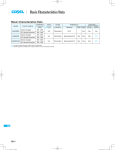
SWIMMING POOL HEAT PUMP UNIT
Installation & Instruction Manual
Hydro-Pro+ Premium
Item codes:
7000855– 7000856– 7000857– 7000858– 7002050– 7002051
CONTENTS
1. Preface
1
2. Specifications
2
2.1 Performance Data of Swimming Pool Heat Pump Unit
2
2.2 Dimensions for Swimming Pool Heat Pump Unit
3
3. Installation and Connection
4
3.1 Installation of System
4
3.2 Swimming Pool Heat Pumps Location
5
3.3 How Close to Your Pool?
5
3.4 Swimming Pool Heat Pumps Plumbing
6
3.5 Swimming Pool Heat Pumps Electrical Wiring
7
3.6 Initial Start-up of the Unit
7
4. Usage and Operation
4.1 Function of the controller
8
8
4.2 Usage of the controller
10
4.3 Parameter table
17
5. Maintenance and Inspection
17
5.1 Maintenance
17
5.2 Malfunction table
18
6. Appendix
19
6.1 Appendix 1
19
6.2 Appendix 2
20
6.2 Appendix 3
24
1. PREFACE
In order to provide our customers with quality, reliability and versatility, this product has
been made to strict production standards. This manual includes all the necessary
information about installation, debugging, discharging and maintenance. Please read this
manual carefully before you open or maintain the unit. The manufacture of this product will
not be held responsible if someone is injured or the unit is damaged, as a result of
improper installation, debugging, or unnecessary maintenance. It is vital that the
instructions within this manual are adhered to at all times. The unit must be installed by
qualified personnel.
The unit can only be repaired by qualified installer centre , personnel or an authorised
dealer.
Maintenance and operation must be carried out according to the recommended time and
frequency, as stated in this manual.
Use genuine standard spare parts only.
Failure to comply with these recommendations will invalidate the warranty.
Swimming Pool Heat Pump Unit heats the swimming pool water and keeps the temperature
constant. For split type unit, The indoor unit can be Discretely hidden or semi-hidden to
suit a luxury house.
Our heat pump has following characteristics:
1 Durable
The heat exchanger is made of PVC & Copper Nickle tube which can withstand
prolonged exposure to swimming pool water.
2 Installation flexibility
The unit can be installed outdoors or indoors.
3 Quiet operation
The unit comprises an efficient rotary/ scroll compressor and a low-noise fan motor,
which guarantees its quiet operation.
4 Advanced controlling
The unit includes micro-computer controlling, allowing all operation parameters to be
set. Operation status can be displayed on the LED wire controller. Remote controller can be
chosen as future option.
1
2.SPECIFICATION
2.1 Performance data of Swimming Pool Heat Pump Unit
*** REFRIGERANT : R410A
Model
Hydro-Pro+ premium 7
Hydro-Pro+ premium 10
kW
6.0
8.0
Btu/h
20400
27200
kW
1.41
1.87
A
6.4
8.5
230V~/50Hz
230V~/50Hz
1
1
Compressor
rotary
rotary
Fan Quantity
1
1
W
120
120
RPM
850
850
horizontal
horizontal
dB(A)
51
54
Water Connection
mm
50
50
Water Flow Volume
m 3/h
2.5
3.4
Water Pressure Drop (max)
kPa
Unit Net Dimensions (L/W/H)
mm
10
10
See the drawing of the units
Unite Shipping Dimensions (L/W/H)
mm
See package label
kg
See nameplate/See package label
UNIT
Heating Capacity
Heating Power Input
Running Current
Power Supply
Compressor Quantity
Fan Power Input
Fan Rotate Speed
Fan Direction
Noise
Net Weight/Shipping Weight
UNIT
Model
Hydro-Pro+ premium 14
Hydro-Pro + premium 19
kW
11.5
15.5
Btu/h
39100
52700
kW
2.48
3.48
A
11.3
15.8
230V~/50Hz
230V~/50Hz
1
1
Compressor
rotary
scroll
Fan Quantity
1
1
W
120
120
RPM
850
850
horizontal
horizontal
dB(A)
56
56
mm
50
50
Water Flow Volume
3
m /h
5.0
6.5
Water Pressure Drop (max)
kPa
10
10
Unit Net Dimensions (L/W/H)
mm
See the drawing of the units
Unite Shipping Dimensions (L/W/H)
mm
See package label
kg
See nameplate/See package label
Heating Capacity
Heating Power Input
Running Current
Power Supply
Compressor Quantity
Fan Power Input
Fan Rotate Speed
Fan Direction
Noise
Water Connection
Net Weight/Shipping Weight
2
2.SPECIFICATION
2.2 The dimensions for Swimming Pool Heat Pump Unit
Hydro-Pro+ premium 7/Hydro-Pro+ premium 10
unit mm
Water Inlet
¦50
Water Outlet
¦50
683
Drainage
¦25
1003
455
430
630
Water Inlet
¦50
875
H ydro-Pro+ premium 14 / Hydro-Pro+ premium 19
Water Outlet
¦50
Drainage
¦25
Horizontal vision
1118
500
475
790
Vertical vision
3
unit mm
3.INSTALLATION AND CONNECTION
3.1 Installation illustration
Sand filter
Water inlet
(or other type filter)
Water pump
Valve
Water supply
Water outlet
Pool
Chlorinator cell
Installation items:
The factory only provides the main unit and the water unit; the other items in the illustration
are necessary spare parts for the water system ,that provided by users or the installer.
Attention:
Please follow these steps when using for the first time
1.Open valve and charge water.
2.Make sure that the pump and the water-in pipe have been filled with water.
3.Close the valve and start the unit.
ATTN: It is necessary that the water-in pipe is higher than the pool surface.
4
3.INSTALLATION AND CONNECTION
3.2 Swimming Pool Heat Pumps Location
The unit will perform well in any outdoor location provided that the following three factors are
presented:
1. Fresh Air - 2. Electricity - 3. Pool filter piping
The unit may be installed virtually anywhere outdoors. For indoor pools please consult the
supplier. Unlike a gas heater, it has no draft or pilot light problem in a windy area.
70
0m
2000mm
500mm
DO NOT place the unit in an enclosed area with a limited air volume, where the units
discharge air will be re-circulated.
DO NOT place the unit to shrubs which can block air inlet. These locations deny the unit of a
continuous source of fresh air which reduces it efficiency and may prevent adequate heat
delivery.
Air inlet
m
30
Air outlet
0
25
0m
m
800mm
m
0m
70
0m
Air outlet
1000mm
Air inlet
m
3.3 How Close To Your Pool?
Normally, the pool heat pump is installed within 7.5 metres of the pool. The longer the
distance from the pool, the greater the heat loss from the piping. For the most part ,the piping
is buried. Therefore, the heat loss is minimal for runs of up to15 meters(15 meters to and from
the pump = 30 meters total), unless the ground is wet or the water table is high. A very rough
estimate of heat loss per 30 meters is 0.6 kW-hour,(2000BTU) for every 5 ¡ difference in
temperature between the pool water and the ground surrounding the pipe, which translates to
5
3.INSTALLATION AND CONNECTION
3.4 Swimming Pool Heat Pumps Plumbing
The Swimming Pool Heat Pumps exclusive rated flow titanium heat exchanger requires no
special plumbing arrangements except bypass(please set the flow rate according to the
nameplate). The water pressure drop is less than 10kPa at max. Flow rate. Since there is no
residual heat or flame Temperatures, The unit does not need copper heat sink piping. PVC
pipe can be run straight into the unit.
Location: Connect the unit in the pool pump discharge (return) line downstream of all filter
and pool pumps, and upstream of any chlorinators, ozonators or chemical pumps.
Standard model have slip glue fittings which accept 32mm or 50 mm PVC pipe for
connection to the pool or spa filtration piping. By using a 50 NB to 40NB you can plumb 40NB
Give serious consideration to adding a quick coupler fitting at the unit inlet and outlet to allow
easy draining of unit for winterizing and to provide easier access should servicing be
required.
From pump
PVC COUPLER
RECOMMENDED(Provided)
To pool
CONDENSATION
DRAIN
BARB FTG
Condensation: Since the Heat pump cools down the air about 4 -5¡, water may condense on
the fins of the horseshoe shaped evaporator. If the relative humidity is very high, this could
be as much as several litres an hour. The water will run down the fins into the basepan and
drain out through the barbed plastic condensation drain fitting on the side of the basepan.
This fitting is designed to accept 20mm clear vinyl tubing which can be pushed on by hand
and run to a suitable drain. It is easy to mistake the condensation for a water leak inside the
unit.
NB: A quick way to verify that the water is condensation is to shut off the unit and keep the
pool pump running. If the water stops running out of the basepan, it is condensation. AN
EVEN QUICKER WAY IS to TEST THE DRAIN WATER FOR CHLORINE - if the is no chlorine
present, then it's condensation.
6
3.INSTALLATION AND CONNECTION
3.5 Swimming Pool Heat Pumps Electrical Wiring
NOTE: Although the unit heat exchanger is electrically isolated from the rest of the unit, it
simply prevents the flow of electricity to or from the pool water. Grounding the unit is still
required to protect you against short circuits inside the unit. Bonding is also required.
The unit has a separate molded-in junction box with a standard electrical conduit nipple
already in place. Just remove the screws and the front panel, feed your supply lines in
through the conduit nipple and wire-nut the electric supply wires to the three connections
already in the junction box (four connections if three phase). To complete electrical hookup,
connect Heat Pump by electrical conduit, UF cable or other suitable means as specified (as
permitted by local electrical authorities) to a dedicated AC power supply branch circuit
equipped with the proper circuit breaker, disconnect or time delay fuse protection.
Disconnect - A disconnect means (circuit breaker , fused or un-fused switch) should be
located within sight of and readily accessible from the unit, This is common practice on
commercial and residential air conditioners and heat pumps. It prevents remotely-energizing
unattended equipment and permits turning off power at the unit while the unit is being
serviced.
3.6 Initial startup of the Unit
NOTE- In order for the unit to heat the pool or spa, the filter pump must be running to
circulate water through the heat exchanger.
Start up Procedure - After installation is completed, you should follow these steps:
1. Turn on your filter pump. Check for water leaks and verify flow to and from the pool.
2. Turn on the electrical power supply to the unit, then press the key ON/OFF of wire
controller, It should start in several seconds.
3. After running a few minutes make sure the air leaving the top(side) of the unit is
cooler(Between 5-10 ¡)
4. With the unit operating turn the filter pump off. The unit should also turn off automatically,
5. Allow the unit and pool pump to run 24 hours per day until desired pool water emperature is
reached. When the water-in temperature reach setting, The unit just shuts off. The unit will
now automatically restart (as long as your pool pump is running)when the pool temperature
drops more than 2¡below set temperature.
Time Delay- The unit is equipped with a 3 minute built-in solid state restart delay included to
protect control circuit components and to eliminate restart cycling and contactor chatter.
This time delay will automatically restart the unit approximately 3 minutes after each control
circuit interruption. Even a brief power interruption will activate the solid state 3 minute
restart delay and prevent the unit from starting until the 5 minute countdown is completed.
Power interruptions during the delay period will have no effect on the 3 minute countdown.
7
4. USAGE AND OPERATION
4.1 Function of controller
Main display area
OFF
ON
A
F min
SET
TEMP
IN
C VOL
3
MODE
SET
TEMP
OUT
2
Aux. Display area
1
5
4
Button functions:
NO
Symbol
Name
Function
Mode
Press this button can start up or shut down the unit,
cancel the current operation or back to the upper
interface
Press this button can switch modes or save
parameter setting.
3
Clock
Press this button can set the clock and timer
4
Up
5
Down
1
2
On/off
MODE
SET
Press this button can move up or increase
parameter value.
Press this button can move down or decrease the
parameter value.
8
4. USAGE AND OPERATION
Display functions:
Symbol
A
Function
Meaning
Cooling
It is showed when the unit in cooling mode.
Heating
It is showed when the unit in heating mode and flashed
in defrosting.
Automatic
It is showed when the unit in automatic mode.
Electricheating
It is showed when the unit in electric-heating mode.
ON
Timer on
It is showed when the unit sets the timer on
OFF
Timer off
It is showed when the unit sets the timer off
IN
Inlet water
OUT
TEMP
It is showed when the main display area gives the inlet
water temperature.(measured value)
It is showed when the AUX display area gives the outlet
Outlet water water temperature.(measured value)
Temperature It is showed when the main/ AUX display area gives
temperature
It is showed when the main display area gives the water
flow value
VOL
Flow
min
Minute
F
Fahrenheit
It is showed when the main/AUX display area
gives Fahrenheit value
C
Centigrade
It is showed when the main/AUX display area
gives centigrade value
SET
Parameter
setting
It is showed when the parameter can be setted.
Lock
It is showed when the main display area gives minute value
It is showed when the keyboard is locked.
9
4. USAGE AND OPERATION
4.2.The controller usage
4.2.1 Starting up and shutting down
In the off interface, press"
" for 0.5s can start up the unit, and aux. display-area shows
water outlet temperature; In the running interface, press"
" for 0.5s can shut down the unit
and aux. display-area shows ¡OFF¡.
Attention: the operation of Starting up and shutting down can only be done in the main interface.
For example:
Water inlet
temperature Water outlet
Water outlet
Actual Mode display
temperature
temperature Actual Mode display
Press¡
TEMP
OUT
MODE
SET
¡
C
TEMP
IN
MODE
SET
TEMP
OUT
for 0.5 second
can switch
between unit
on and unit off
On unit
Off unit
4.2.2 Modes switching
If it is cold/ heat unit, in the main interface, you can switch different modes of cooling,
MODE
SET If it is cold/heat and electric heat unit, in the main
heating, auto mode by pressing
interface, you can switch different modes of cooling, heating, auto mode, electric heating
mode, heating and electric heating modes by pressing MODE
SET
Attention: The modes switching is useless if the unit you buy is single-cold/ single-heat unit.
For example:
A
Press
TEMP
OUT
MODE
SET
MODE
SET
Press
TEMP
OUT
MODE
SET
MODE
SET
TEMP
OUT
Press
Press
TEMP
OUT
10
MODE
SET
MODE
SET
MODE
SET
MODE
SET
TEMP
OUT
MODE
SET
4. USAGE AND OPERATION
4.2.3 Temperature setting
In the main interface press
or
and the current mode target-temperature flashes, then
press
to increase the temp.value, or press
to decrease it.
Press
can save setting parameter and back to the main interface
Press
can not save setting parameter but back to the main interface
MODE
SET
Attention£If there is no operation for 5s system would remember parameter setting and back
For example:
Cooling target temperature
Press
or
C
TEMP
IN
TEMP
OUT
SET
TEMP
MODE
SET
C
TEMP
OUT
MODE
SET
Press
or
to change the value
Press
to save value
MODE
SET
C
TEMP
IN
TEMP
OUT
MODE
SET
SET
TEMP
C
TEMP
OUT
setting
MODE
SET
4.2.4 Clock setting
In the main interface press
twice, hours will start to flash and press
to increase value
or press
to decrease value and press
to save setting
At the same time, minute start to flashing press
to increase value or press
to decrease
value and press
to save setting.
Press
can not save setting parameter and back to main interface.
Attention: If there is no operation for 5s system will remember parameter setting and back to
the main interface.
For example:
11
4. USAGE AND OPERATION
Hour minute
C
TEMP
IN
TEMP
OUT
Flashing
Press
MODE
SET
TEMP
OUT
Press
Flashing
C
TEMP
IN
TEMP
OUT
Press
to save hour
value setting
MODE
SET
C
TEMP
IN
¡
Press
or
¡
¡
¡
C
TEMP
OUT
MODE
SET
Flashing
C
TEMP
IN
TEMP
OUT
Flashing
TEMP
IN
MODE
SET
MODE
SET
Flashing
Press
or
¡
C
TEMP
IN
TEMP
OUT
MODE
SET
Press
to save minute value setting
C
TEMP
IN
TEMP
OUT
12
MODE
SET
4. USAGE AND OPERATION
4.2.5 Timer setting
In the main interface press
hold on 2 seconds and "on" is flashing, at this time,
you can set the timer on means the unit timer is on then press
again and hold on
2 seconds and "off" is flashes you can set the timer off means the unit timer is off.
If you want cancel the timer off, In the "off" flashing interface press
to cancel
Attention 1) If there is no operation for 5s, the system will remember clock setting and back to
the main interface.
2) By pressing "
" till the "off" flashing, you can set the timer off without timer on.
Flashing
ON
C
TEMP
IN
MODE
SET
TEMP
OUT
C
TEMP
IN
Press
MODE
SET
TEMP
OUT
for 2 seconds
Press
Flashing
Flashing
ON
ON
C
TEMP
IN
press
or
MODE
SET
TEMP
OUT
C
TEMP
IN
MODE
SET
TEMP
OUT
Press
Flashing
Flashing
ON
ON
C
TEMP
IN
TEMP
OUT
press
or
MODE
SET
C
TEMP
IN
Press
TEMP
OUT
13
MODE
SET
4. USAGE AND OPERATION
Flashing Flashing
Flashing
ON
ON
OFF
OFF
C
TEMP
IN
MODE
SET
TEMP
OUT
Press
or
¡
ON
ON
OFF
C
MODE
SET
TEMP
OUT
C
TEMP
IN
Press
MODE
SET
TEMP
OUT
The timer on and off has been set
Flashing Flashing
ON
ON
OFF
OFF
C
TEMP
OUT
Flashing Flashing
OFF
TEMP
IN
TEMP
IN
MODE
SET
TEMP
OUT
Flashing Flashing
Press
or
C
TEMP
IN
Press
Press
C
TEMP
IN
MODE
SET
TEMP
OUT
14
MODE
SET
4. USAGE AND OPERATION
4.2.6 Cancel the timer setting
Press
for 2s and "ON" is flashing at this time, press
to cancel the setting of timer on;
It is the same way to cancel the setting of timer off .
For example:
The timer on/off has been set
"ON" is flashing
ON
ON
OFF
OFF
TEMP
IN
TEMP
OUT
C
Press
MODE
SET
for 2s
"OFF" is flashing
C
TEMP
IN
The setting of timer on has
been cancelled
Press
OFF
TEMP
IN
TEMP
OUT
OFF
C
Press
MODE
SET
for 4s
TEMP
OUT
C
TEMP
IN
TEMP
OUT
C
TEMP
IN
The setting of timer off has
been cancelled
Press
MODE
SET
TEMP
OUT
MODE
SET
15
MODE
SET
4. USAGE AND OPERATION
4.2.7 Keyboard lock
To avoid mis-operation, please lock the controller after parameter setting.
At the main interface, press
for 5 seconds, the keyboard will be locked.
When the keyboard is locked, press
or 5 seconds, the keyboard will be unlocked.
NOTES: When the unit is in alarming state, the key lock can be removed automaticly.
C
TEMP
IN
TEMP
OUT
Hold on
C
TEMP
IN
MODE
SET
TEMP
OUT
MODE
SET
Locked
4.2.8 Malfunction display
There will be malfunction code showing on the controller screen when relative malfunction
occurs.
You can refer to the malfunction table to find out the failure cause and solution.
For example:
MODE
SET
16
Water inlet temp. Sensor failure
4. USAGE AND OPERATION
4.3 Parameter table
Default
Remark
Heating inlet target temp.
27ºC
Adjustable
Cooling inlet target temp.
27ºC
Adjustable
Auto inlet target temp.
27ºC
Adjustable
Meaning
5.1 Maintenance
Check the water supply device and the release often. You should avoid the condition of no
water or air entering into system, as this will influence unit's performance and reliability.
You should clear the pool/spa filter regularly to avoid damage to the unit as a result of the
dirty of clogged filter.
The area around the unit should be dry, clean and well ventilated. Clean the side heating
exchanger regularly to maintain good heat exchange as conserve energy .
The operation pressure of the refrigerant system should only be serviced by a certified
technician .
Check the power supply and cable connection often,.Should the unit begin to operate
abnormally, switch it off and contact the qualified technician.
Discharge all water in the water pump and water system ,so that freezing of the water in the
pump or water system does not occur. You should discharge the water at the bottom of
water pump if the unit will not be used for an extended period of time. You should check the
unit thoroughly and fill the system with water fully before using it for the first time after a
17
5. MAINTENANCE AND INSPECTION
5.2 Malfunction table
You can refer to the malfunction table to find out the failure cause and solution.
malfunction
display
Indicator
Power on
resolution
Reason
Off
On
Normal working
Inlet temp. Sensor failure
P01
1 On 1 off
The temp. Sensor is broken or short circuit
Check or change the temp. Sensor
Outlet temp. Sensor failure
P02
2 on 1 off
The temp. Sensor is broken or short circuit
Check or change the temp. Sensor
Recovery temp. Sensor failure
P033
3 on 1 off
The temp. Sensor is broken or short circuit
Check or change the temp. Sensor
Check or change the temp. Sensor
Ambient temp. Sensor failure
P04
4 on 1 off
The temp. Sensor is broken or short circuit
Coil 1 temp. Sensor failure
P15
5 on 1 off
The temp. Sensor is broken or short circuit
Coil 2 temp. Sensor failure
P25
5 on 1 off
The temp. Sensor is broken or short circuit
Check or change the temp. Sensor
Suction 1 temp. Sensor failure
P17
7 on 1 off
The temp. Sensor is broken or short circuit
Check or change the temp. Sensor
P27
7 on 1 off
The temp. Sensor is broken or short circuit
Check or change the temp. Sensor
P181
8 on 1 off
The temp. Sensor is broken or short circuit
Check or change the temp. Sensor
P182
8 on 1 off
The temp. Sensor is broken or short circuit
Check or change the temp. Sensor
P19
9 on 1 off
The temp. Sensor is broken or short circuit
Check or change the temp. Sensor
P29
9 on 1 off
The temp. Sensor is broken or short circuit
Check or change the temp. Sensor
High pressure1 protection
E11
11 on 1 off
The high-preesure switch is broken
Check the pressure switch and cold circuit
High pressure2 protection
E21
11 on 1 off
The high-preesure switch is broken
Check the pressure switch and cold circuit
Low pressure1 protection
E12
12 on 1 off
The low-preesure switch is broken
Check the pressure switch and cold circuit
Low pressure2 protection
E22
12 on 1 off
The low-preesure switch is broken
Check the pressure switch and cold circuit
Water flow failure
E03
13 on 1 off
No water/little water in water
system
Check the pipe water flow and water pump
Water flow over-low failure
E035
13 on 1 off
No water/little water in water
system
Check the pipe water flow and water pump
Elctrical-heat over heat failure
E04
14 on 1 off
Electrical-heat is over heat
Check or change electrical-heat
Compressor 1 overload failure
E101
21 on 1 off
Compressor is overload
Check the compressor functionality
Compressor 2 overload failure
E201
21 on 1 off
Compressor is overload
Check the compressor functionality
Check the pipe water flow and whether water
system is jammed or not
Suction 1 temp. Sensor failure
Discharge 1 temp. Sensor failure
Discharge 2 temp. Sensor failure
Antifreezing 1 temp.
Sensor failure
Antifreezing 2 temp.
Sensor failure
Check or change the temp. Sensor
Water-inlet and outlet
temp. difference
E06
16 on 1 off
Water flow is not enough
and low differential pressure
The system 1use side
antifreezing protection
E171
17 on 1 off
Water flow is not enough
Check the pipe water flow and whether water
system is jammed or not
The system 2 use side
antifreezing protection
E271
17 on 1 off
Water flow is not enough
Check the pipe water flow and whether water
system is jammed or not
The system 1heat source
side antifreezing protection
E172
17 on 1 off
Water flow is not enough
Check the pipe water flow and whether water
system is jammed or not
The system 2 heat source
side antifreezing protection
E272
17 on 1 off
Water flow is not enough
Check the pipe water flow and whether water
system is jammed or not
E19
19 on 1 off
The ambient temp. Is low
/
E29
19 on 1 off
The ambient temp. Is low
/
Discharge Temp. Of system 1
is too high
P182
8 on 1 off
The compressor is overload
Check the compressor functionality
Discharge Temp. Of system 2
is too high
P282
8 on 1 off
The compressor is overload
System protection
E05
8 on 1 off
The protection system is failure
The primary anti-freezing
protection
The secondary anti-freezing
protection
Defrosting
Communication failure
/
/
Flashing
E08
/
Communication failure between
wire controller and main board
18
Check the compressor functionality
Check each protection point of the system
/
Check the wire connection between
remote wire controller and main board
6.APPENDIX
Appendix 1.Connection of PCB illustration
N
N
L
RO 01
RO 02
RO 03
RO 04
RO 05
RO 06
RO 07
RO 08
RO 09
CN1
CN5
CN6
GND
GND
GND
GND
GND
GND
GND
GND
GND
GND
GND
GND
GND
GND
GND
GND
GND
GND
GND
GND
GND
GND
GND
GND
GND
GND
GND
DI/DO 1
GND
DI/DO 2
DI 11
DI 12
DI 10
DI 09
DI 08
DI 07
DI 06
DI 05
DI 03
DI 02
DI 04
AI 12(50K)
AI 10
AI 11(50K)
AI 09
AI 08
AI 07
AI 06
AI 05
AI 03
AI 04
AI 02
DI 01
AI 01
NET
5V
12V
GND
PC4001
Connections explanation:
NO. Symbol
NO. Symbol
Meaning
Meaning
1
AC-L
Live line
21
DI 07
Water flow switch protection input
2
AC-N
Null line
22
DI 08
Electric heater overload protection input
3
RO 01
Compressor 1 output(220VAC)
23
DI 09
Compressor 1 overload protection input
4
RO 02
Compressor 2 output(220VAC)
24
DI 10
Compressor 2 overload protection input
5
RO 03
High speed of fan output(220VAC)
25
DI 11
System protection input
6
RO 04
Low speed of fan output(220VAC)
26
DI 12
Emergency switch input
7
RO 05
Water pump output(220VAC)
27
AI 01
Water input temperature input
8
RO 06
4-way valve output(220VAC)
28
AI 02
Water output temperature output
9
RO 07
Electric heater output(250VAC)
29
AI 03
System 1 fan coil temperature input
10
RO 08
Spray valve output(220VAC)
30
AI 04
System 2 fan coil temperature input
11
RO 09
Alarm system output(220VAC)
31
AI 05
Ambient temperature input
12
DI/DO 1
Mode indicator output
32
AI 06
System 1 antifreeze temperature input
13
DI/DO 2
Emergency switch output
33
AI 07
System ١ antifreeze temperature input
14
DI 01
Flow rate input
34
AI 08
System 1 suction temperature input
15
DI 02
System 1 high pressure protection input
35
AI 09
System 2 suction temperature input
16
DI 03
System 1 low pressure protection input
36
AI 10
No use
17
DI 04
System 2 high pressure protection input
37
AI 11(50K)
18
DI 05
System 2 low pressure protection input
38
AI 12(50K) System 2 discharging temperature input
Connecting to the remote controller
39
CN1
System 2 electric expansion valve output
Phase sequence protection
40
CN6
System 1 electric expansion valve output
19
20
NET GND ١٢V
DI 06
19
System 1 discharging temperature input
6.APPENDIX
Appendix 2 : Explosive view of the unit
MODEL Hydro-Pro+ Premium 10
NO.
Code
Part name
NO.
Code
Part name
1
32008-210098
chassis
22
32008-120009
condenser
2
32008-220035
front plate
23
2000-3909
2-way wire connector
3
20000-220068
weatherproof box
24
32012-210078
controller box
4
95005-310210
LCD wire controller
25
2004-1437
4-way valve
5
32012-210080
fan grill
26
32009-220029
wiring box£black£
6
3500-2701
axial fan
27
2000-3603
low pressure switch
7
32012-210079
controller box cover
28
2002-1451
electronic expansion valve
8
20000-330022
axial fan motor
29
32008-210096
right plate
9
32008-210099
strutting board
30
2001-3605
high pressure switch
10
2000-3510
compressor capacitor
31
20000-140150
needle valve
11
32008-210097
back grill
32
20000-360005
water flow switch
12
32012-210108
motor trestle
33
2000-3242
outlet water temp sensor
13
2000-3242
ambient temp sensor
34
2000-3242
inlet water temp sensor
14
32008-210036
top cover
35
32008-120008
titanium heat exchanger
15
2000-3501
fan motor capacitor
36
3500-1401
liquid-vapor separator
16
2000-1415
screw
37
3400-2203
drain-pipe joint
17
2000-2802
pressure meter
38
32008-210095
center spacer
18
4000-3901
5-way wire connector
39
2001-1163
compressor(N21)
19
20000-340060
3-way cored wire
20
95005-310114
Pc4001 controller
21
2000-3619
relay
Note
20
Note
6.APPENDIX
Appendix 2 : Explosive view of the unit
MODEL Hydro-Pro+ Premium14
NO.
Code
Part name
Note
NO.
Code
Part name
1
32009-210128
chassis
22
35012-120001
condenser
2
32009-220028
front plate
23
20000-340060
3-cored wire
3
20000-220068
weatherproof box
24
32009-210125
controller box
4
95005-310210
LCD wire controller
25
2001-1491
4-way valve
5
34006-210049
fan grill
26
32009-220029
wiring box black
6
2000-2705
axial fan
27
2000-3603
low pressure switch
7
32009-210024
controller box cover
28
20000-140151
electronic expansion valve
8
20000-330019
axial fan motor
29
32009-210131
right plate
9
32009-210025
strutting board
30
2001-3605
high pressure switch
10
2000-3510
compressor capacitor
31
20000-140150
needle valve
11
32009-210130
back grill
32
20000-360005
water flow switch
12
32009-210129
motor trestle
33
2000-3242
outlet water temp sensor
13
2000-3242
ambient temp sensor
34
2000-3242
inlet water temp sensor
14
32009-220027
top cover
35
32009-120013
titanium heat exchanger
15
2000-3508
fan motor capacitor
36
3500-1401
liquid-vapor separator
drain-pipe joint
16
2000-3802
pressure meter
37
3400-2203
17
20000-360007
1-phase AC contactor
38
32009-210124
center spacer
18
2000-3909
2-way wire connector
39
20000-110027
compressor (H51)
19
4000-3901
5-way wire connector
20
95005-310114
Pc4001controller
21
2000-3619
relay
21
Note
6.APPENDIX
Appendix 2 : Explosive view of the unit
MODEL Hydro-Pro+ premium19
NO.
Code
Part name
NO.
Code
Part name
1
32009-210128
chassis
22
35012-120001
condenser
Note
2
32009-220028
front plate
23
2000-3933
3-way wire connector
3
20000-220068
weatherproof box
24
32009-210125
controller box
4
95005-310210
LCD wire controller
25
2001-1491
4-way valve
5
34006-210049
fan grill
26
32009-220029
wiring box (black)
6
2000-2705
axial fan
27
2000-3603
low pressure switch
7
32009-210024
controller box cover
28
20000-140151
electronic expansion valve
8
20000-330019
axial fan motor
29
32009-210131
right plate
9
32009-210025
strutting board
30
2001-3605
high pressure switch
10
2000-3524
compressor capacitor
31
20000-140150
needle valve
11
32009-210130
back grill
32
20000-360005
water flow switch
12
32009-210129
motor trestle
33
2000-3242
outlet water temp sensor
13
2000-3242
ambient temp sensor
34
2000-3242
inlet water temp sensor
14
32009-220027
top cover
35
32009-120013
titanium heat exchanger
15
2000-3508
fan motor capacitor
36
3500-1401
liquid-vapor separator
drain-pipe joint
16
2000-3802
pressure meter
37
3400-2203
17
20000-360007
1-phase AC contactor
38
32009-210124
center spacer
18
2000-3909
2-way wire connector
39
20000-110053
compressor(S76)
19
2000-3920
3-way wire connector
20
95005-310114
PC4001controller
21
2000-3619
relay
22
Note
6.APPENDIX
Appendix 2 : Explosive view of the unit
MODEL Hydro-Pro+ Premium 7
NO.
Code
Part name
NO.
Code
Part name
1
32008-210098
chassis
22
3406-1204
condenser
2
32008-220035
front plate
23
2000-3909
2-way wire connector
controller box
Note
3
20000-220068
weatherproof box
24
32012-210078
4
95005-310210
LCD wire controller
25
2001-1418
4-way valve
5
32012-210080
fan grill
26
32009-220029
wiring box black
6
3500-2701
axial fan
27
2000-3603
low pressure switch
7
32012-210079
controller box cover
28
2003-1402
electronic expansion valve
8
20000-330022
axial fan motor
29
32008-210096
right plate
high pressure switch
9
32008-210099
strutting board
30
2001-3605
10
2000-3504
compressor capacitor
31
20000-140150
needle valve
11
32008-210097
back grill
32
20000-360005
water flow switch
12
32012-210108
motor trestle
33
2000-3242
outlet water temp sensor
13
2000-3242
ambient temp sensor
34
2000-3242
inlet water temp sensor
14
32008-210036
top cover
35
32025-120005
titanium heat exchanger
15
2000-3501
fan motor capacitor
36
3500-1401
liquid-vapor separator
16
2000-1415
screw
37
3400-2203
drain-pipe joint
17
2000-2802
pressure meter
38
32008-210095
center spacer
18
4000-3901
5-way wire connector
39
20000-110077
compressor(H67)
19
20000-340060
3-way cored wire
20
95005-310114
Pc4001 controller
21
2000-3619
relay
23
Note
6.APPENDIX
N
C1
1
N
L
N
K1
WHT
2
C2
BLK
FM
TO POWER
SUPPLY TO PUMP
220-240V~/50Hz
BLU
WHT
ORG
RED
Hydro-Pro+ Premium 7
24
N
N
GND DI /DO 2
DI 12
GND DI /DO 1
Remote out
Remote
Cool\Heat
DI 11
GND
GND
Remote in
DI 10
DI 09
GND
GND
DI 08
GND
N
FS
FS
01
5
6
N
N
3
4
N
7
8
N
L
N
L
CC CR
CS
CS
CR
N
N
N
1
2
COMP
RED
P
L
N
DI 06
GND
FS
K5
P
CC
BLK
CC
RED BLU
DI 07
DI 05
GND
L
DI 04
GND
HP LP
L
SUT
L
AT
L
L
L
GND
N
L
K1
RO 01
DI 03
GND
RO 02
F-H
RO 03
HP
HP
LP
LP
DI 02
GND
GND
K5
RO 05
AI 10
t
5K
5K
t
5K
5K
IT OT CT
RO 04 F-L
RO 06
AI 09
GND
RO 08
GND
4V
RO 07
AI 08
GND
AI 06
AI 07
GND
AI 04
GND
t
AT
AI 03
GND
t
AT
AI 02
GND
5V
GND
AI 01
t
5K
IT
IT
OT
OT
CT
CT
GND
DI 01
GND
Controller
K1
SUT
SUT
RO 09
AI 05
GND
CN1
CN5
CN6
12V
NET
GND
BRN
Y/G
BLU
GND
PC4001
K5
GND AI 12(50)
4V
5
GND AI 11(50)
N
EEV
N
Appendix 3: Circuit diagram of the unit
AT Ambient temperature
COMP Compressor
CT Coil temperature
EEV Electronic expand valve
FM Fan motor
FS Flow switch
HP Highpressure protection
IT Inlet water temperature
K1 Relay ofcompressor
K5 Relay of pump
LP Low pressure protection
OT Outlet water temperature
SUT Suction temperature
4V 4 way valve
6.APPENDIX
CC
N
C1
1
N
L
N
K1
WHT
2
C2
BLK
FM
TO POWER
SUPPLY TO PUMP
220-240V~/50Hz
BLU
WHT
ORG
RED
Hydro-Pro+ Premium 10
25
N
GND DI /DO 2
GND DI /DO 1
Remote out
Remote
Cool\Heat
DI 11
DI 12
GND
DI 10
Remote in
GND
GND
GND
DI 09
N
DI 08
GND
N
FS
FS
01
5
6
N
N
3
4
N
7
8
N
L
N
L
CC CR
CS
CS
CR
N
N
N
1
2
COMP
RED
P
L
N
DI 06
GND
FS
K5
P
L
L
L
DI 07
DI 05
GND
L
DI 04
GND
HP LP
L
SUT
L
AT
BLK
CC
RED BLU
GND
N
L
K1
RO 01
DI 03
GND
RO 02
F-H
RO 03
HP
HP
LP
LP
DI 02
GND
GND
K5
RO 05
AI 10
GND AI 12(50)
RO 06
AI 09
GND
RO 08
4V
RO 07
AI 08
GND
t
5K
5K
K1
GND
AI 06
AI 07
GND
AI 04
5K
IT OT CT
t
5K
t
AT
AI 03
GND
t
AT
AI 02
GND
5V
GND
GND
t
5K
IT
IT
OT
OT
CT
CT
AI 01
GND
GND
DI 01
GND
Controller
K5
SUT
SUT
RO 09
AI 05
GND
CN1
CN5
CN6
12V
NET
BRN
Y/G
BLU
GND
PC4001
N
4V
5
RO 04 F-L
EEV
GND AI 11(50)
N
Appendix 3: Circuit diagram of the unit
AT Ambient temperature
COMP Compressor
CT Coil temperature
EEV Electronic expand valve
FM Fan motor
FS Flow switch
HP Highpressure protection
IT Inlet water temperature
K1 Relay ofcompressor
K5 Relay of pump
LP Low pressure protection
OT Outlet water temperature
SUT Suction temperature
4V 4 way valve
6.APPENDIX
N
L
CC
N
KM1
CS
RED
CR
WHT
C1
1
2
N
N
Remote
in
Remote
Cool/heat
Remote
out
GND DI /DO 2
GND
DI 12
DI 11
GND
GND DI /DO 1
DI 10
GND
GND
DI 09
GND
DI 08
N
N
N
01
5
6
N
N
7
8
N
3
4
COMP
CC CR
CS
N
N
P
L
DI 07
DI 06
N
N
L
L
P
L
GND
GND
FS
DI 05
GND
N
FS
N
N
BLK
CC
RED BLU
N
L
DI 04
GND
LP
HP LP
N
SUT
N
AT
N
5K
t
1
2
K5
FS
RO 02
RO 01
DI 03
GND
L
F-H
DI 02
GND
HP
LP
HP
RO 03
K1
RO 04 F-L
RO 05 K5
AI 10
GND AI 12(50)
RO 06
GND
RO 07
AI 09
GND
RO 08
AI 08
GND
GND
AI 04
GND
KM1
SUT
AI 06
AI 07
GND
AT
AT
AI 03
GND
K5
L
IT OT CT
t
5K
AI 02
GND
CT
t
5K
OT
CT
t
5K
5V
AI 01
GND
GND
IT
OT
GND
IT
DI 01
GND
BLU
Controller
t
5K
12V
NET
GND
BRN
Y/G
PC4001
SUT
RO 09
AI 05
GND
CN1
CN5
CN6
4V
5
GND AI 11(50)
4V
EEV
N
N
Appendix 3: Circuit diagram of the unit
C2
BLK BLU
FM
TO POWER
SUPPLY TO PUMP
220-240V~/50HZ
ORG
Hydro-Pro+ Premium 14
26
WHT
RED
AT Ambient temperature
COMP Compressor
CT Coil temperature
EEV Electronic expand valve
FM Fan motor
FS Flow switch
HP High pressure protection
IT Inlet water temperature
KM1 Contactor of compressor
K5 Relay of pump
LP Low pressure protection
OT Outlet water temperature
SUT Suction temperature
4V 4 way valve
6.APPENDIX
KS
CC
CC
BLK BLU
FM
ORG
WHT
RED
L
Hydro-Pro+ Premium 19
27
3
4
01
5
6
GND
GND DI /DO 2
DI 11
GND
GND DI /DO 1
DI 10
GND
DI 12
DI 09
GND
DI 08
GND
N
N
N
N
Remote
in
Remote
Cool/heat
Remote
out
DI 06
DI 07
FS
GND
FS
DI 05
GND
GND
N
L
DI 04
GND
L1
N
KM1
C3
L
220-240V~/50HZ
KM1
5
C2
1
L1
2
KS
TO POWER TO PUMP
SUPPLY
N
CR
CS
N
L N
C1
L
DI 03
GND
N
N
FS
N
7
8
N
N
HP LP
CH
RED
KS N N
CC
L
P
L N
COMP WHT
CC CR
CS
CS CS CS
L L L
BLU N
RED L
K5
RO 01
RO 02
K1
N
50K
ET
N
5K
SUT
N
5K
AT
1
2
BLK
LP
F-H
DI 02
GND
HP
LP
HP
ET
RO 03
RO 04 F-L
AI 10
RO 07
t
t
N N N
IT OT CT
GND
RO 05 K5
AI 09
GND
RO 08
4V
RO 06
AI 08
AI 07
GND
AI 04
GND
t
SUT
AI 06
GND
AI 03
GND
AT
AT
AI 02
GND
CT
t
5K
OT
CT
t
5K
5V
AI 01
GND
GND
IT
IT
OT
t
5K
DI 01
GND
Controller
SUT
RO 09
AI 05
GND
CN1
CN5
CN6
12V
NET
GND
BRN
Y/G
BLU
GND
PC4001
GND AI 12(50)
KM1
GND
5
GND AI 11(50)
K5
4V
EEV
ET
N
N
Appendix 3: Circuit diagram of the unit
AT Ambient temperature
COMP Compressor
CT Coil temperature
CH Compressor heater
EEV Electronic expand valve
ET Exhausttemperature
FM Fan motor
FS Flow switch
HP Highpressure protection
IT Inlet water temperature
KM1 Contactor of compressor
KS Relay of compressor start
K5 Relay of pump
LP Low pressure protection
OT Outlet water temperature
SUT Suction temperature
4V 4 way valve