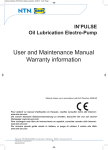
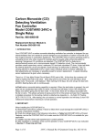
1
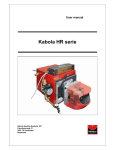
Production from 2006-09
GB 122i
THIS DOCUMENT MUST ABSOLUTELY BE READ BEFORE STARTING THE
INSTALLATION.
INSTRUCT USER AND LEAVE THIS DOCUMENT WITH THE HEATER FOR
REFERENCE.
Instruction manual version GB122i Argus
Heaters for GB
Date: 16-10-2008
Heaters for natural gas G20 and Propane
This installation and user manual contains the installation and users instructions for the standard and
axial model of the TR-series. For the centrifugal, duct or air curtain models, additional instructions are
provided in an appendix. This manual is produced specifically for the gas, electrical and mechanical
installer. Also, it contains instructions how to install, use and maintain the heater. To assure a safe and
efficient operation of this unit air heater, it is absolutely necessary to apply the instructions in the
manual(s) correctly.
Page
1
INTRODUCTION:
2
2
CONTENT:
2
3
GENERAL
3
3.1
4
GUARANTEE
3
APPLICATION RESTRICTIONS
4.1
4.2
3
PRE-CHECK
PROTECTION DEGREE
3
3
5
TECHNICAL DETAILS:
4
6
INSTALLATION
5
6.1
6.2
6.3
6.4
6.5
6.6
7
POSITIONING
POSITIONING THE HEATER
GAS CONNECTION
ELECTRICAL CONNECTION
AIR INTAKE / COMBUSTION PRODUCTS DISCHARGE
AIR INTAKE FROM INSIDE B22
5
5
6
6
7
8
FUNCTIONING OF THE UNIT
7.1
7.2
7.3
7.4
7.5
7.6
8
8
GENERAL
HEAT DEMAND
DELTA-T-REGULATION (TEMPERATURE CONTROLLED DE-STRATIFICATION FAN)
SUMMER VENTILATION
HIGH LIMIT PROTECTION
DESCRIPTION HEATER CONTROL HC
8
9
9
9
9
10
PUTTING INTO OPERATION AND ADJUSTMENT
8.1
8.2
8.3
8.4
9
10
GENERAL
START BY USING THE SERVICE-BUTTON
START BY USING THE THERMOSTAT
TO SIMULATE A LOCK OUT CONDITION
10
11
11
11
ADJUSTING THE GAS-CONTROL
10
10.1
11
11.1
11.2
11.3
12
12.1
12.2
12.3
13
12
PROBLEM SOLVING
12
GENERAL
12
MAINTENANCE / SPARE PARTS
14
GENERAL INSPECTION
INSPECTION OF THE HEATER
SPARE PARTS
14
14
15
EXAMPLES ELECTRICAL INSTALLATION
15
INSTALLATION WITH MODULATING ROOM THERMOSTAT
INSTALLATION OF MORE HEATERS ON ONE THERMOSTAT
INSTALLATION WITH ON/OFF THERMOSTAT
15
15
16
ELECTRICAL DIAGRAM
Instructions Air heaters type TR (GB 122i)
17
Page 2/17
General
The TR unit air heaters are direct fired gas heaters with an output up to 100 kW. The heat
exchanger is built with S-shaped tubes, each having its own atmospheric burner. Depending on
the power of the heater, there are more burners and tubes in one appliance.
Further the heater is provided with a sophisticated control sequence to maintain a comfortable
room temperature and even air distribution.
It is imperative that the installation and maintenance of this appliance are carried out by
qualified gas engineers, and strictly according to our instructions.
2.1
Guarantee
The guarantee is invalidated when the air heaters are not installed in accordance with this
manual.
!
!
Important!
The installation and maintenance of this air heater should be performed by an
authorised competent installer in accordance with this manual.
3.1
Pre-check
Before unpacking and installation, please check (i.e. on the data badge) if the heater
corresponds to the order and if it is suitable for the local present provisions (gas type, gas
pressure, electrical supply etc.)
The installation must comply with all applicable local and national standards.
The installation of the air heater must be in accordance with the relevant requirements of the
Gas Safety Regulations (for example in GB; The Institute of Gas Engineers IGE UP-1 and 2),
Building Regulations and the IIE Regulations also incorporating the gas safety (installation and
use) regulations. Other national and/or local regulations may apply (the Local Authority, Fire
Officer and Insurers)
The competent installer must make sure the heater operates correctly and must instruct the
user about the safe operation of the heater.
A ventilation gap of 30 cm is required from the top and bottom of the heater to any flammable
materials.
If this heater is taking its combustion air from within the room in which it is located, the
necessary ventilation requirements must be followed for gas safety regulations.
The heater should not be installed in areas containing any corrosive or explosive vapours, high
moisture or dust concentrations, negative pressures or temperatures higher than 30°C; please
consult Winterwarm or your supplier, otherwise the guarantee will become invalidated.
Make sure that the warm air can be blown out freely. There should absolutely be no (possibility
of) materials within 5m from the front of the heater.
The heater has been tested in detail on safety and correct operating settings before leaving the
factory. It has been adjusted for the type of gas that is stated on the data badge. Should there
be any doubt, please contact your supplier.
3.2
Protection degree
The heater has a protection degree of IP20, which means it can be used in a dry and not very
dusty environment. This also goes for the Winterwarm room-thermostat.
Instructions Air heaters type TR (GB 122i)
Page 3/17
"
#
!
Type
Maximum nominal heat input (Nett)
Minimum nominal heat input (Nett)
Efficiency max power
Efficiency min power
Maximum heat output
Minimum heat output
Max air output (+ temp increase)
Throw horizontal (max)
Throw vertical (max. warm)
Sound level
Electric Connection
Thermostat communication bussystem (low voltage)
Power Consumption
Power Consumption Amps
Gas connection
pressure swich point
Flue / air connectionvoer
parallel
Minimum suspension height horizontal throw
Minimum suspension height vertical throw
kW
kW
%
%
kW
kW
m3/h
m
m
dB(A)
Vac
TR10
10,8
6,5
91,9
87,9
9,9
5,7
2000
12,0
4,0
42
230
TR15
16,2
9,7
91,6
87,4
14,9
8,5
2000
12,0
4,0
42
230
TR20
21,5
14,5
91,8
88,6
19,7
12,8
2000
12,0
4,0
42
230
TR24
26,0
17,5
92,1
89,1
23,9
15,6
3000
16,0
5,0
45
230
W
A
G"
mbar
mm
m
m
200
0,9
1/2"
0,98
80
1,7
4,0
200
0,9
1/2"
0,98
80
1,7
4,0
200
0,9
1/2"
0,8
80
1,7
4,0
190
0,8
1/2"
0,75
80
1,7
4,0
20
20
20
20
30
30
30
30
1110
290
630
760
250
190
110
Ø 80
Ø 80
1/2"
250
235
80
175
50
50
1110
290
630
760
250
190
110
Ø 80
Ø 80
1/2"
250
235
80
175
50
50
2000
290
630
760
250
190
110
Ø 80
Ø 80
1/2"
250
235
80
175
50
55
1040
540
630
80
760
763
426
250
190
110
Ø 80
Ø 80
1/2"
470
145
95
75
80
67
Natural gas G20
Min supply pressure
Class
Max gas consumption
d injectors
burnerpressure high
burnerpressure low
CO2 high (indication)
NOx klass
Gas category II2H3P
G20 (H) mbar
Clas.
G20 (H) m3/h
nx Ø mm
(H) mbar
mbar
G20 (H) %
Propane G31,
Gas category II2H3P
G31 (P) mbar
Clas.
G31 (P) kg/h
nx Ø mm
(P) mbar
mbar
G31 (P) %
Min supply pressure
Class
Max gas consumption
d injectors
burnerpressure high
burnerpressure low
CO2 high (indication)
NOx klass
Dimensions
A
B
C
D
E
F
G
H
I
K
M
N
O
P
R
S
T
U
weight
TR28 TR40
30,0
43,5
20,5
30,0
92,3
91,7
89,5
88,7
27,7
39,9
18,3
26,6
3000 4000
16
22
5
6
45
48
230
230
Argus Link
200
300
0,9
1,3
1/2"
3/4"
0,98
0,98
80
100
1,7
1,7
4
4
TR50
54,0
36,5
91,6
88,4
49,5
32,3
5000
26
6
50
230
TR60
65,5
44,0
91,8
88,9
60,1
39,1
6000
28
6
50
230
TR80 TR100
87,0 110,0
59,0
73,5
92,4
92,0
89,7
90,0
80,4 101,2
52,9
66,2
8000 10.000
30
30
6
6
52
54
230
230
425
1,8
3/4"
1,50
100
1,7
4
350
1,5
3/4"
1,50
130
1,7
4
600
2,6
3/4"
1,15
130
1,7
4
750
3,3
3/4"
1,50
130
1,7
4
20
20
20
20
20
20
B22, C12, C32
1,1
1,7
2,3
2,8
3,2
4,6
5,7
6,9
9,2
11,6
2x 2,1 3x 2,1 4x 2,1 5x 2,1 6x 2,1 8x 2,3 10x2,3 12x 2,3 16x 2,3 22x 2,3
10,1
10,2
10,0
9,5
9,0
7,3
7,30
8,00
7,80
8,0
3,7
3,65
4,5
4,4
4,1
3,5
3,3
3,6
3,5
3,6
7,1
7,4
8
7,2
8,0
8,0
8
8,0
7,8
7,2
3
3
3
3
3
3
3
3
3
3
30
30
30
30
30
30
B22, C12, C32
0,9
1,3
1,7
2,1
2,4
3,5
4,3
5,2
6,9
8,8
2x 1,4 3x 1,4 4x 1,4 5x 1,4 6x 1,3 8x 1,4 10x 1,4 12x 1,4 16x 1,4 22x 1,4
23,8
24,2
22,7
20
27,5
23,0 22,40 23,5 22,80 20,1
8,9
9,0
10,5
9,5
13,0
11,0
10,4
10,5
10,5
9,0
7,9
8,6
9
8,3
9,5
9,2
9,4
9,1
9
8,6
3
3
3
3
3
3
3
3
3
3
mm
mm
mm
mm
mm
mm
mm
mm
mm
mm
mm
mm
mm
mm
mm
mm
mm
mm
kg
1040
540
630
80
760
763
426
250
190
110
Ø 80
Ø 80
1/2"
470
145
95
75
80
70
1130
540
700
120
760
763
426
250
225
140
Ø 100
Ø 100
3/4"
470
195
95
165
70
85
1130
1000
700
80
760
763
875
580
60
225
Ø 130
Ø 130
3/4"
930
185
175
165
90
135
1130
1000
700
120
760
763
875
580
60
225
Ø 130
Ø 130
3/4"
930
185
175
165
90
150
1130
1250
700
120
760
763
1125
580
60
225
Ø 130
Ø 130
3/4"
1180
185
300
165
60
200
R
E
Diam M
S
D
1130
670
700
120
760
763
550
250
225
140
Ø 100
Ø 100
3/4"
600
195
95
165
80
100
G
Electra
C
H
P
B
K
F
i
U
Gas O"
4X M10
4X M10
F
T
A
Instructions Air heaters type TR (GB 122i)
Page 4/17
$
5.1
!
Positioning
•
min
300
Check and make sure that the support is solid
enough.
• Keep sufficient distance between the heater and any
obstruction, in connection with safety and access for
service and maintenance. Pay particularly attention
to any flammable materials. Please take into account
the possibility to open the door of the heater for the
necessary service and maintenance work. Make
sure the airflow to and from the heater is unhindered.
Any obstacles should be at least 5 metres away from
the front of the heater.
• The heater can be installed horizontally or vertically, the positioning is almost completely
free. See the drawings.
• The heater is provided with 3 times four M10 threaded sockets on the top, bottom and
behind as fixing points. Use preferably the Winterwarm suspension kits.
• Make sure that after fitting, there is no mechanical tension on any connecting gas or electric
supplies.
• If the heater is installed with the air stream vertically downwards, the maximum suspension
height is 6 meters. Otherwise the warm air will not reach the floor.
Attention:
See the application-restrictions in this manual (Chapter 4) for more installation restrictions.
Min 650
5.2
SERVICE
Positioning the heater
Horizontally
Horizontally upside down
At an angle down
0 - 90°
At an angle down
0 - 90°
horizontal but not with an
inclination.
Instructions Air heaters type TR (GB 122i)
Vertically
Page 5/17
Wall console (standard)
TR20 t/m TR100
art.nr. GA.8580
Wall console (turnable) art.nr. GA.8670
TR20 t/m TR50
+90°
turnable horizontal or
turnable forward
0°
-90°
5.3
45°
Gas connection
The gas supply line has to meet the national valid requirements and possibly the local
requirements of the building inspector, police or fire brigade. (In GB it must comply with Gas
Engineers publication UP-1 and UP-2 together with BS 6891.)
A manual isolation valve in the supply line must be placed within reach of the heater, and all gas
lines must be mounted without any mechanical tension.
When testing the supply lines with pressures above 60 mbar, this manual valve at the heater
must be closed.
The working and standing supply pressure must be between 17mbar and 30mbar, measured at
the inlet pressure nipple of the gas control in the heater.
The burner pressure is pre-adjusted (high/low, see technical details). The burner pressure can
be measured on the P-out measure point on the gas valve.
5.4
Electrical connection
5.4.1 230Vac supply
The installation must comply with local and national requirements, (as well as IEE regulations).
The unit heater is delivered completely internally wired. Where controls of any type are to be
added (e.g. room thermostat), the relevant wiring diagrams must be followed. Never use a room
thermostat to interrupt the electrical supply to the heater!
Make provisions to completely isolate the heater for maintenance purposes. This can be an
isolation switch (min. 3mm contact opening gap), a power plug or a non-switched fuse spur.
The wiring diagram for the heater can be found towards the end of this manual.
The supply is 230Vac. with earth. The control circuit is a two wire low voltage Argus-link bus
communication.
5.4.2 Room thermostat
The heater can be controlled by special Winterwarm room thermostats:
The DB8; specially designed digital clock thermostat with optimizer. It can control 1 to 8 air
heaters.
The Multi Therm Standard; specially designed digital thermostat. It can control 1 to 8 air
heaters.
The Interface board; specially designed interface module for connecting the air heaters with
other appliances. (0-10V signal, On/Off signal, high/low signal, reset and different
outputs.
ON/OFF thermostat; The heater can be controlled with a simple on/off thermostat. In that case
some important functions will not be available, like reset and modulation.
Instructions Air heaters type TR (GB 122i)
Page 6/17
In all cases the communication between the heater and the thermostat is based on a two wire,
low-voltage connection. In the appliance the wire for the thermostat has to be connected to
connection 4 and 5 (see also electrical wiring diagram).
In all cases: make sure you use a screened cable.
Cable length:
0 – 50 m
min. 0,13 mm2
50 – 100 m
min. 0,25 mm2
100 – 250 m (max.)
min. 0,50 mm2
The given length is the maximum length between the units and the thermostats.
Never mount the thermostat near aerials of internal communication networks.
These emit radiation that could lead to disturbance of the thermostat. Always keep
some meters distance.
In an EMC disturbance sensitive environment, a so-called sealed “twisted pair”
cable must be used. Before connecting, switch off the tension from the heater.
Connect the earth shield of the cable only to the earth terminal in the heater.
When mounting the thermostat, pay attention to the following items:
• Mount the thermostat in a place where the air can circulate freely pass the thermostat. Make
sure that the sun does not shine directly upon the thermostat (in the winter). Do not place
the thermostat on a cold wall. Place the thermostat on an inner wall, free from draught.
• Never place the thermostat into the throw of the heater.
5.4.3 Fuses
On the heater control (HC) there are two fuses. (See electrical wiring diagram.)
F1 and F2 are in the power supply of the heater. Replace the fuse only by a fuse of the same
type.
5.5
Air intake / combustion products discharge
Check for compliance with local/national regulations.
The combined Winterwarm combustion-air supply/combustion-gas outlet device (roof terminal or
wall terminal) has to be used, only then the installation is CE approved. See installation
drawings.
Never connect a roof terminal for condensing appliances; rain can damage the heater through
the discharge pipes.
Make sure the roof terminal is at least 0,5m above roof level. Use only pipes and bends for
overpressure with profiled sealing-rings.
5.5.1 Maximum flue length
Vertical: 9 meters is the maximum length between the heater and its flue outlet.
Horizontal: 6 meters is the maximum length between the heater and the flue outlet.
When bends are used, the pressure drop will increase and therefore a 90° bend will count as 2
metres and a 45° bend as 1 metre. All flue pipes must be of the same diameter as the flue
spigots on the heater, and all flue joints must be sealed. For further information regarding the
flue system please contact your supplier.
5.5.2 Air intake from outside C12, C32
In case of a vertical flue outlet, the outlet must at least point out 0,5m above the roof surface.
Make sure that the air intake openings are free of any obstruction.
Always take the local regulations into account.
Instructions Air heaters type TR (GB 122i)
Page 7/17
Vertical discharge
TR20-28:
DDV 80/125 art.nr. IA.8202
TR40-50:
DDV100/150 art.nr. IA.8101
TR60-100: DDV130/200 art.nr. IA.8305
5.6
Horizontal discharge
CT 80/125 art.nr. IA.8113
CT100/150 art.nr. IA.8112
CT130/200 art.nr. IA.8312
Air intake from inside B22
No influence
< 23°
%
&
7.1
General
> 0,5 m
No influence
> 0,5 m
In case the unit is used as class B22 (air intake from inside the room) the air outlet needs to be
placed in the area where there is less or little influence from the building. See drawing here
below. In that case, the outlet must point out at least 0,5m above roof level. For details see local
regulations.
In case the inclination is bigger than 23 ° please pay special attention to the
combustion exit.
Put the delivered gauze in the air inlet stump of the heater, in order to avoid things to
fall in. See drawing.
No influence
> 23°
' ( #
The unit can heat as well as ventilate. By using the temperature-sensor on the unit and the one
in the room-thermostat, the temperature-difference between the two in the room is monitored.
Should the difference become higher than the set value, due to the fact that warm air has
accumulated underneath the roof, the system-fan will start and push the warm air down, acting
as a de-stratification fan.
Instructions Air heaters type TR (GB 122i)
Page 8/17
7.2
Heat demand
If the thermostat indicates heat demand, the following cycle will start:
1. Pre purge: The electronic circuit board acknowledges the heat-demand and the flue
booster fan will start running for 30 seconds. (Display print
1)
2. Ignition: After 30 seconds of pre purge, the electrode will spark for max. 5 seconds, the
gas valve is opened and the gas-air mixture will ignite. (Display print
2)
3. Burn: When the flame is detected (Display print
b) the unit will modulate to the desired
load after ca. 15 seconds. Depending on the given load, the system fan will start
modulating (step-less) as well. The air heater will always run for a minimum of 4
minutes. This is to evaporate eventual condense in the discharge system.
4. End of heat demand: When the heat demand ends, the burner will switch off and the
system fan will continue to run for ca. 3 minutes in order to cool the unit down (Display
print
P).
The unit will try to ignite twice before lockout on flame fault.
In the case of flame failure during operation, the heater will attempt one restart.
When the heater is in lockout you see in the display intermittent A1. On the display of the room
thermostat you see failure 1.
7.3
Delta-T-regulation (temperature controlled de-stratification fan)
In case there is no heat demand, the delta-T-regulation will be active.
When the temperature-difference between the sensor on the unit (the NTC) and the sensor in
the thermostat is bigger than the set value (factory setting standard 8°C), the system fan will
start, at a regulated speed, depending on the differential temperature difference. This operation
ensures an even temperature distribution throughout the building, thus acting as a fully
automatic variable de-stratification fan.
Should this delta-T-regulation not be required, this regulation can be switched off in the menu
Program Settings on the room thermostat. See user manual of the special Winterwarm Room
thermostat.
7.4
Summer ventilation
It is possible to let the ventilator run on a certain speed in the summer. Please follow the
instructions in the manual of the thermostat.
7.5
High limit protection
The unit contains 2 temperature protections. The NTC thermostat monitors the air temperature
electronically. Should the temperature, in a first step, become too high, the burner will modulate
to the minimum input and the system fan will modulate to the maximum speed.
When the temperature still increases, the burner will switch off (on the display you see
intermittent E1). When the heat exchanger has been cooled down to normal level, the burner
will start automatically.
Should the temperature increase to an unacceptable level, the heater will stop (on the display
you see intermittent A2). Only after a manual reset, the heater can start again. Manual reset can
be done on the electronic circuit board or with the special Winterwarm room thermostat
Instructions Air heaters type TR (GB 122i)
Page 9/17
7.6
Description heater control HC
The heater control (HC) controls the unit and communicates with the room thermostat.
Functions integrated in the heater control HC are:
-two wire communication with room thermostat
-spark ignition on burner
-ionisation flame guard on burner
-controlling the gas valve
-modulating the burner
-modulating the system fan
-guarding the temperature of the heat exchanger
-LED signals status of heater, heat demand: green, failure: red
-Status of heater on 8 segment display on heater control HC
-reset of heater
-service mode function
Lay-out print board
J2
J8
J4
J9
J7
Fuse 5AT
J15
U11
S1
J12
T2
J6
S2
on
1 23 4567 8
S3
0
1
Argus vision
J2 Main power connection 230V
J4 Connection for gas valve and system fan
J6 Connection for room thermostat, appliance recognition and the status LEDs green and red
J7 Earth burner
J8 Modulating coil gas valve, fluebooster
J9 not used
J12 Connections for temperature sensors
J15 Ionisation selector
F1 & F2 Fuses 2x 5AT
U11 Status display
S1 Reset service button
S2 Micro switch heater no. Standard 1 to “on”
S3 Power supply thermostat when S2 no.1 to “on”, then S3 on 1, otherwise S3 to 0
T2 Ignition transformer, connection for igniters
)
8.1
'
*!+
General
Prior to packaging, each unit is checked in detail on safety and well functioning. It is among
other things adjusted to the right efficiency of combustion. In general, the heater does not need
to be adjusted after installation, only a check of well functioning is necessary by a competent
person.
Instructions Air heaters type TR (GB 122i)
Page 10/17
The high/low burner pressures can be adapted, if necessary. However, only do this when the
burner pressure turns out to be incorrect after measuring (differences smaller than 0,5mbar do
not need to be adjusted). Never touch the adjusters injudiciously!
In case the installation is done following these instructions, the unit can be put on. Make sure
the gas line is clean, gastight and free from air.
Turn on the electrical supply with the main switch, and leave the door of the heater open, in
order to watch the first start and so become familiar with the functioning of the unit.
In case of warmth demand, the heater will always run for at least 4 minutes, even if the warmth
demand is fulfilled within this time.
The heater will attempt twice to start again, before going on flame failure. Then reset is
necessary.
Do not forget to instruct the end user about a safe use of the heater (presence of gas, place of
the manual gas valve!), the operation of the heater (lock-out indication and reset) and about the
necessary maintenance. This manual must be left with the end user.
8.2
Start by using the service-button
Press the service-button once for 10 seconds, and the unit will commence the ignition-cycle; (30
seconds pre-purge, ignition, 15 seconds flame stabilize, modulating operation)
The burner will then start on minimum load Display print
L/b.
By pressing the service-button again, the burner will go to maximum load. Display print
H/b
Pressing the service-button for a third time will put the unit into normal operation (depending on
if there is warmth demand from the room thermostat).
8.3
Start by using the thermostat
Put the thermostat in the highest position. The start sequence is always the same as under 8.2.
8.4
To simulate a lock out condition
Close the manual gas supply valve. The heater will go on lock-out after a restart attempt. The
display on the electronic circuit board shows [ ]. The red LED will light as well. Check also the
function of the reset button (with gas valve open again), and observe if the heater starts
smoothly.
Display on the print board
stand-by
Pre-purge
System checks and 30 sec. pre purge of the fluebooster
Ignition
The ignitionelectrode sparks 5 sec. and the gas valve opens,
within 5 sec. flame detection should occur.
After 15 sec. stabilisation time, the heater will modulate to the
desired power. The heater will run at least 4 minutes.
The heater will cool the heat exchanger for 3 minutes, and the
fluebooster will post purge for 1 minute.
The system fan is running on the summer ventilation mode.
Burn
Post purge
Blinking
…
Blinking
/
Stand-by
Summer
ventilation
Delta-T-regulation The system fan is running on low position on Delta-Tregulation
Service Low
The heater is running on the service mode. When the heater
/
runs, the heater will run on minimum power.
Service High
The heater is running on the service mode. When the heater
runs, the heater will run on maximum power.
Blinking
Instructions Air heaters type TR (GB 122i)
Page 11/17
,
*!
' # ' !!-
In principle, it is not necessary to adjust the gas
control after putting the unit into operation.
In case it needs to be adjusted, (e.g. after fitting a
new one), this must be done only by a qualified
person. Only use calibrated instruments! A poor
adjustment can lead to overheating and / or
production of toxic carbon monoxide!
The burner pressures can be adjusted as follows:
- Remove the cover from the gascontrol with the
help of a (small) screwdriver.
- Start the unit and first set the high burner
pressure by turning screw ‘B’ (external 8mm).
The High / low coil must be energised !
- De-energise coil (disconnect wire) and set low
burner pressure by turning screw ‘C’ (slot for screwdriver) Do not set lower than 3 mbar in
order to avoid problems with inter-lightning of burnerstrips.
Attention: Always check each burner pressure after any adjustment, as they influence each
other.
Always check the CO production of the heater!!! Too much CO usually means the mixture is too
rich. Adjust this if necessary with the two adjusters (see above)
.
/ + ! 0 '
10.1 General
When it turns out that the problem is not caused by the external circumstances (i.e. no electric
supply power or no gas), please take the following instructions into account. Please remember
the built in waiting times of the heater (do not react too soon!) and the code on the display on
the electronic circuit board.
To simplify the investigation of the failing heater please check first:
• the fuses as well as the wires and plugs in the heater for possible loose contacts.
• Use first the service-button to put the heater in run mode, try later the room thermostat.
Volatile lock out : Can only be reset by hand
Internal failure
Defective print board
Blinking
No flame
Blinking
Blinking
Blinking
Blinking
Blinking
Within 5 sec flame, then flame failure: Cause 1
No flame: Cause 2
Exchanger too hot Heater stops because the temperature of the heat exchanger is
too high: Cause 3
Sensor error
Temperature sensor on heat exchanger error: Cause 4
Too many flame
failures
Too many flame failures on ionization: Cause 1, 5
Internal error
Defective print board
Safety relays
2nd temperature limiter (optional) switched: Cause 3, 10
Blinking
Instructions Air heaters type TR (GB 122i)
Page 12/17
Flame
Flame detection when there should not be a flame
Fluebooster
Fluebooster does not run: Cause 6
Fluebooster runs: Cause 7
Blinking
Blinking
Non volatile lockout: will disappear when the error is cleared.
Blinking
Blinking
Blinking
Blinking
Internal defect
Defective print board
1st temperature
safety
Heater stops because the temperature of the heat exchanger is
too high. When the heater is cooled down, the heater will
restart: Cause 3
Heater recognition does not work: Cause 8
Selection
resistance
Selection
resistance
Reset error
Heater recognition does not work: Cause 8
Too many switches on reset button: Cause 9
Blinking
Cause 1: Within 5 sec flame, then flames failure.
• The flame is not detected. Check the ignition cable and electrode. (cable resistance 1K
ohm
• The heater has electrically a poor earth.
• The print board is defective.
Cause 2:
• There is not enough gas pressure.
• The burner pressure is too low, adjust the gas valve
• The gas valve does not open, check during ignition on 230V on the valve.
• Check whether the ignition electrode sparks, replace cable, electrode
Cause 3: Heat exchanger too hot
• Check if the system fan blows enough air.
• Check the setting of the gas valve, the heater may be overloaded.
Cause 4: Temperature sensor on heat exchanger error.
• The sensor has internally 2 sensors. These differ too much. Measure the resistance from
each sensor, the resistance should be 20K at 25° en 25K at 20°. If the measured values
differ too much, replace sensor.
• Rotate the sensor ¼ turn, so that the contact point is different on the sensor housing.
Cause 5: Too many flame failures while burning
• The setting of the gas valve is not ok, adjust the gas valve
• The flue outlet is blocked
Cause 6: The fluebooster does not run
• fan is blocked or the wiring is bad
• fan is defective
Cause 7: The fluebooster fan runs.
• Check if the fan runs smoothly.
• Check if the fan is not polluted.
• Check if there is water (condense) in the hoses from the pressure switch.
Cause 8: Selection resistance error
• Check the appliance recognition part, replace if necessary
Instructions Air heaters type TR (GB 122i)
Page 13/17
Cause 9: Reset button error
• Too many switches on reset button in a short period of time. This error will disappear
after some time, or if the main power is disconnected for a while.
Cause 10: 2nd STB (optional) switched
• Heaters equipped with 2 system fans have a second temperature limiter. The second
limiter has switched. Check the fan where this sensor is mounted.
• Check the wiring.
Heater does start, but shows other problems.
a) System fan (M1) does not start or does not vary in speed; Check first the functioning of this
fan by connecting it to 230 Volt. Check with a multi-meter if the different lower tensions are
present on the fan. The fuse could have failed. If the motor is OK, the cause of the problem
must be in the heater control HC, as the heater control HC dictates the different voltages to
the fan-motor. In that case, replace the heater control HC.
1!
!
The heater must be inspected and cleaned regularly (once a year) by a qualified installer who
understands this appliance.
This is all the more important when the circumstances are heavier, especially in case of dust,
humidity, high frequency of switching on/off etc.
Activities:
11.1 General inspection
•
•
Check the overall condition of the installation. Check the heater, the thermostat, the wires
and the gas line.
Check the burner pressure and the CO2 and CO levels from the flue. Do so when operating
the heater in maximum and minimum load. (service mode: press 10 seconds on the reset
button, the heater will run on minimum power, press the button again, the heater will run on
maximum load.)
11.2 Inspection of the heater
Before starting the inspection, switch off the electric power to the heater with the maintenanceswitch and close the manual gas valve.
• Take out the burner, by unscrewing the 4 socket screws.
• Check the heat exchanger from the inside for dirt and/or damage.
• Check the burner on damage and clean the ignition electrode if necessary. CAUTION: do
not twist the electrode out of shape!
• Check the air supply and the flue discharge.
• Clean if necessary the inside of the heater with a vacuum cleaner.
• In case the heat exchanger is dirty on the outside, clean it with a soft brush. Never use a
steel wire brush!
• Clean the fan-grid with a vacuum cleaner and a brush.
• Put the burner back in (renew the gasket)
After this, check the heater on efficiency of combustion and adjust this if necessary.
Check if the heater operates correctly.
Instructions Air heaters type TR (GB 122i)
Page 14/17
11.3 Spare parts
2 +
TR10
IB.3200
IB.3400
IX.3460
IB.3402
IB.4500
GA.3394
IB.4816
IB.5908
IK.3994
GA.3902
GA.6712
TR15
IB.3200
IB.3400
IX.3460
IB.3402
IB.4500
GA.3394
IB.4816
IB.5908
IK.3994
GA.3902
GA.6712
!
TR20
IB.3200
IB.3400
IX.3460
IB.3402
IB.4500
GA.3394
IB.4816
IB.5908
IK.3996
GA.3902
GA.6712
TR24
IB.3200
IB.3400
IX.3460
IB.3402
IB.4500
GA.3394
IX.4200
IB.5908
IK.3996
GA.3902
GA.6712
TR28
IB.3200
IB.3400
IX.3460
IB.3402
IB.4500
GA.3394
IX.4200
IB.5908
IK.3994
GA.3902
GA.6712
TR40
IB.3200
IB.3400
IX.3460
IB.3402
IB.4512
GA.3394
IX.4203
IB.5908
IK.3994
GA.3902
GA.6714
!
TR50
IB.3200
IB.3400
IX.3460
IB.3402
IB.4512
GA.3394
IH.4206
IB.5908
IB.3902
GA.3902
GA.6714
TR60
IB.3200
IB.3400
IX.3460
IB.3402
IB.4516
GA.3394
IX.4200
IB.5908
IB.3902
GA.3902
GA.6716
TR80
IB.3200
IB.3400
IX.3460
IB.3402
IB.4516
IB.3314
IX.4203
IB.5908
IB.3906
GA.3902
GA.6716
TR100
IB.3200
IB.3400
IX.3460
IB.3402
IB.4516
IB.3314
IH.4206
IB.5908
IB.3902
GA.3902
GA.6716
Installer
Neutal
12.1 Installation with modulating room thermostat
• Connect the heater to 230Vac
• Connect the thermostat to the terminals according to the
diagram. (terminal 4 and 5)
•
On the print the switches S2
S2
S3
and S3 need to be set as
ON
0 1
follows: S2 switch 1 at the ON
1 2 3 4 5 6 7 8
position, and S3 at 1.
L (230V AC)
Description
Burner
Ignition electrode
Ignitioncable
Ionisation electrode
Flue fan
Gas controle valve
System Fan
Controle board 166HA
pressureswitch
NTC cable set
Gasket set TR
Thermostat (bus)
22°C
1 2 3
4 5
The changement of these switches need to be performed
without power on the Heater, otherwise these settings take no effect.
In all cases: make sure you use a screened cable.
Cable length:
0 – 50 m
min. 0,13 mm2
50 – 100 m
min. 0,25 mm2
100 – 250 m (max.)
min. 0,50 mm2
The given length is the maximum length between the units and the thermostats.
12.2 Installation of more heaters on one thermostat
One room thermostat can control 8 heaters. To connect the heaters is very simple. The two
wires for the thermostat can be connected to heater one, from heater one to heater two, from
heater two to heater three etc. etc. Connect always on terminal 4 and 5. See also the diagram.
Standard factory setting: switch 1 “on”
Each heater needs its own unique number to have the
heater recognised by the room thermostat. The number
of the heater can be set by the micro switch on the
heater control HC in the heater. The number at the
upper position of the switch is the given number for that
heater. Make sure that each heater has is own unique
number. If more than one heater have the same
number, the system does not work.
S2
ON
S3
0
1
Heater 1
0
1
Heater 2
0
1
Heater 3
1 2 3 4 5 6 7 8
ON
1 2 3 4 5 6 7 8
ON
1 2 3 4 5 6 7 8
The changement of these switches need to be performed without power on the Heater,
otherwise these settings take no effect.
In all cases: make sure you use a screened cable.
Cable length:
0 – 50 m
min. 0,13 mm2
50 – 100 m
min. 0,25 mm2
100 – 250 m (max.)
min. 0,50 mm2
The given length is the maximum length between the units and the thermostats.
Instructions Air heaters type TR (GB 122i)
Page 15/17
More heaters on one roomthermostat
1 2 3
4 5
1 2 3
4 5
1 2 3
4 5
L (230V AC)
Neutal
L (230V AC)
Heater 8
Neutal
L (230V AC)
Heater 3
Neutal
L (230V AC)
Heater 2
Neutal
Heater 1
1 2 3
4 5
Max. 8 Heaters
Communication bus:
2 wires; low voltage
1 2 3
in heaters:
micro switch on printboard.
ON
S2
S3
0
1
Heater 1
0
1
Heater 2
0
1
Heater 3
1 2 3 4 5 6 7 8
ON
4 5
1 2 3
Neutal
4 5
L (230V AC)
Heater 3
Neutal
L (230V AC)
Heater 2
Neutal
Heater 1
L (230V AC)
22°C
1 2 3
4 5
Important:
Whem more heaters on one thermostat, each next
heater must have its own number (2 til 8).
Only in heater nr 1 S3 to ON, other heaters S3 to 0.
Do not change clamb 4 with 5 between the heaters.
22°C
1 2 3 4 5 6 7 8
ON
1 2 3 4 5 6 7 8
12.3 Installation with ON/OFF Thermostat
The heater can be connected to an ON/OFF thermostat.
In this case, the heater runs on maximum power only. It will not modulate.
The manual reset in case of fan error will have to be done with the reset button on the main
board.
The following settings have to be made on the main board in the heater:
• The micro switches on the main board have to be set to OFF,
S2
see example.
S3
ON
• The switch S3 has to be set to 1.
0 1
• The thermostat has to be connected to the clamps 4 and 5 in
1 2 3 4 5 6 7 8
the heater.
• In the case that more than 1 heater is connected to 1 thermostat, do not exchange clamp
4 with clamp 5 between the heaters. This will result in permanent burning of the heaters.
• The changement of these switches need to be performed without power on the Heater,
otherwise these settings take no effect.
Instructions Air heaters type TR (GB 122i)
Page 16/17
0
-T
1
S3
20K@25°C
-T
20K@25°C
dP
-T
yellow
green
white
brown
yellow
yellow
white
brown
J12
8
4
7
3
6
2
5
1
Whem more heaters on one thermostat, each next
heater must have its own number (2 til 8).
Only in heater nr 1 S3 to 1, other heaters S3 to 0.
Micro switches S2 standard 1 to ON, and S3 to 1.
1 2 3 4 5 6 7 8
ON
S2
Temperature
sensors on heat
exchanger
Air pressure
switch
AirTemperature
sensor on
heater
20K@25°C
F2
2
J6
Page 17/17
5
8
Thermostat (bus)
22°C
4
1
F1
2 x 5AT
J2
1
1 green/yellow
puple
N
red
LED 1
red
(opt.)
2
3
9
1
3
2
LED 2
green
(opt)
white
3 brown
green
2 blue
10
12
6
4
grey
black
blue
4
11
5
166HA
green/yellow
J4
7
3
4
12
Apliance
recognition
R3
4k7
4
2
5
R2
4k7
7
5
black
13
1
black
6
10
M1
blue
gasvalve
1
14
11
2
J7
When M3
else bridge
STB
3
green/yellow
J15
8
9
T2
11
M2
J8
M3
8
10
7
6
2
1
9
5
4
3
white
white
12
1 2 3
Neutal
Installer
L (230V AC)
/ 1b
Date: 17-05-2006
white
white
black
TR series
Title:
Get: MF
ventilators
blue
L
white
Instructions Air heaters type TR (GB 122i)
blanc
Flue booster
green/yellow
Ver: B
4 5
Nr.:
R120
Auth:
Modulating coil
DC or AC
SIT
AC Hon.
DC
11 12 13 14
GB
22°C
Thermostat (bus)
'
+