1
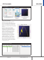
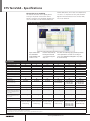
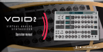
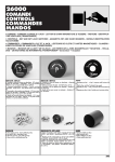
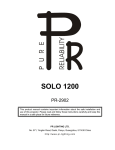
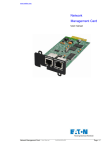
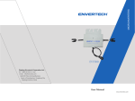
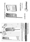
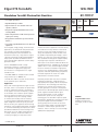
Elgar ETS TerraSAS
1kW-1MW
Standalone TerraSAS Photovoltaic Simulator
60-1000 V
• Low output capacitance
115
• High bandwidth up to 30kHz
• High resolution I-V curve simulates static and
dynamic conditions
208
400
480
• Designed for high speed Maximum Power Point
Tracking (MPPT)
• Can be integrated into a multi-channel system for
higher power testing
• Energy Harvest and Oscilloscope measurements
built in. *
• Low voltage, high bandwidth version for DC Power
Optimizers
For microgrids, energy storage, and inverter test
applications, the TerraSAS™ series photovoltaic
(PV) simulators are specifically designed to
emulate the dynamic electrical behavior of a
terrestrial PV solar array. They offer low output
capacitance and high closed loop bandwidth to
keep up with the advanced Maximum Power
Point Tracking (MPPT) algorithms used in today’s
grid-tied inverters.
The ETS Embedded TerraSAS is a high
performance solution in a small form factor
that combines an agile power supply with
an innovative I-V curve generator in a single
standalone unit.
• ETS 600 / 1000: For isolated and non-isolated
string inverters up to 1000Vdc Voc.
• ETS 60 / 80 / 150: For use with micro-inverters
or DC optimizers up to 150Vdc Voc
Application
Many solar inverters generate AC ripple on their
DC input, which is connected to the photovoltaic
array. For single phase inverters, the frequency
of this ripple is twice the line frequency (120 Hz
for US models). The simulator’s power supplies
must not suppress this ripple as a function of
their regulation loop. An increasing number
of inverters (and virtually all micro-inverters)
accurately measure amplitude and phase of the
ripple voltage and current to quickly track the
MPP of the array. This approach allows tracking
the MPP at a much higher speed when compared
to conventional dithering techniques (also called
perturbate-and-observe). Faster tracking of the
MPP results in a much higher overall efficiency
in cloudy conditions, where the irradiance is
constantly changing. It is likely that all solar
inverters will use this approach in the near future,
since end users are very sensitive to the overall
efficiency of their solar energy installations. To
satisfy this requirement, the PV simulator must
be capable of reproducing the voltage / current
behavior of a solar array at the ripple frequency.
Most standard switching power supplies employ
very large output capacitors and inductors in
their output circuits and are unable to deliver the
required performance - regardless of the response
speed of the I-V curve controller. Elgar’s TerraSAS
line of PV simulators are based on high speed
versions of our standard products, where output
capacitors and other speed-limiting components
have been adjusted. This results in a speed
improvement of 10 times or better.
Proprietary features built into the PV controller
hardware and firmware, combined with our
high speed power supplies, deliver the required
performance. This technology was extensively
tested on micro-inverters and is ready to test
the next generation of inverters. The required
performance is delivered by high speed switching
power supplies and advanced DSP signal
processing techniques. In some conditions
traditional DC power sources using IGBT
technology do not meet MPPT response speed
requirements, depending on the MPPT principles.
Our power supplies use Power MOSFETs,
which typically switch ten times as fast as the
most recent IGBTs. Higher switching frequency
translates to smaller output capacitors and
inductors - which is the key to a successful high
speed power supply design
AMETEK
Programmable Power
9250 Brown Deer Road
San Diego, CA 92121-2267
USA
* - Available Q4 2013
858.458.0223
[email protected]
05082013
ETS TerraSAS
Product Overview
The ETS series standalone TerraSAS consists of
a programmable DC power supply with control
software and GUI interface, output isolation,
and a unique PV simulation engine that provides
the I-V curve. This combination of hardware,
software, and firmware allows the TerraSAS
to simulate test protocols or combinations of
events that a real-world solar installation will be
subjected to.
The included software allows modeling of a PV
panel without an extensive knowledge of solar
array parameters. The only parameters required
for a simulation are the open circuit voltage (Voc),
short circuit current (Isc), and the peak power
parameters Vmp and Imp. Changes to these
parameters allow the shape of the I-V curve to be
adapted to any fill factor between 0.5 and 0.95.
Once an I-V curve has been generated, changes
to the irradiation level or temperature can be
modified on the fly to test the behavior of a
grid tied inverter under realistic conditions for
cloud shadowing and panel temperature rise.
Long term weather simulations can be loaded
and run to determine the amount of energy
harvest delivered in a given situation. Inverter
designers use these accuracy and efficiency tests
to optimize real MPP search modes.
Scalability
Power supplies are available in 850W, 5kW,
10kW, and 15KW increments. The 80V units
are available in two power levels: 1200W
for microinverters and 850W for the latest
generation microinverters and DC power
optimizers. The bandwidth on the 850W version
has been improved to 30kHz by adding a linear
regulation output stage. 600V units are available
in 5kW, 10kW, and 15kW versions depending on
Isc requirements. 1000V units are rated 10kW.
All versions are easily connected in parallel to
scale output power up to handle microinverters,
string inverters, and even utility scale inverters.
Many models can also be connected in series to
handle higher voltage tests. Please refer to the
connection diagrams located in the User Manual
and follow appropriate wiring codes before
connecting ETS PV simulators in series or parallel.
Real time I-V curve display
The Elgar Real time I-V curve display is updated
20 times per second to illustrate dynamic inverter
behavior (operating point and sweep amplitude).
Compared to other commercially available solar
array simulators with an update rate of only 1Hz,
this allows more accurate analysis of the inverter’s
actual MPP tracking ability.
www.ProgrammablePower.com
ETS TerraSAS
1kW-1MW
Basic I-V Curve simulation
1. Create and add a curve
2. Drag and drop this
curve onto the
channel tile
3. Click the ON/OFF button on
the channel tile to
execute curve
Basic I-V Curve simulation
The Elgar TerraSAS user interface is intuitive,
graphically colorful and simple to learn. I-V
curves are created by entering simple parametric
data or by importing data from the NREL SAM
database. It is not necessary to use Java Script or
any other Script hosting to create an IV curve and
execute it.
Dynamic Irradiance profile display
The Elgar TerraSAS profile display of Irradiance
and temperature is unique and innovative. It
enables inverter designers to easily load and
implement standards based cloudy condition
scenarios, such as the weighted efficiency
measurements called out in EN50530 or
California Energy Commission. The ability to
model dynamic performance profiles allows
complex test validation in any situation in a
repeatible, reliable manner. These standard
profiles are impossible to simulate with a real
array. It can also be controlled to a very fine
degree and real profiles can be entered and run
from actual speed to 100 times actual speed for
accelerated lifecycle tests.
TerraSAS dynamic irradiance profile display
858.458.0223
[email protected]
ETS TerraSAS - Specifications
Photovoltaic array modeling
mismatched panels, which result in multiple hump
I-V curves. It is important to verify that the MPPT
algorithm finds and settles on the universal MPP,
not a local maximum.
This feature allows the user to quickly define
an array of PV panels connected in series or
parallel. Using this array modeling capability, the
user can simulate such real world conditions as
Photovoltaic array modeling
Import module data
from embedded
Sandia database and
create I-V Curve
Build the array model by
binding to the desired
curve and specifying the
array size
The effects of shadowing, aging and faulty modules
can be previewed in real time. the resulting I-V
curve can be dragged and dropped to any output
for inverter testing.
Specifications
Model Number1
ETS60X14C
ETS80X10.5C
ETS150X5.6C
ETS80X15C
ETS600X _ _
ETS1000 X10
Output voltage, Voc (V)
Output current, Isc (A)
Output power @ 0.85FF (W)
MPP tracking speed (Hz)2
I-V curve resolution (# of pts)
Output capacitance
Output isolation (Vpk)
60
14
714
250
1024
< 10nF
±1000
80
10.5
714
250
1024
< 10nF
±1000
150
5.6
714
250
1024
< 10nF
±1000
80
15
1020
120
1024
< 70uF
± 600
600
8.3, 16.7, 25
4250, 8500, 12750
200
1024
< 70uF
± 600
1000
10
8500
200
1024
< 3uF
± 1400
Available I/O
Ethernet
Ethernet
Ethernet
Ethernet
Ethernet
Ethernet
2V
2V
2V
2V
10V
10V
AC Input Voltage, V
Remote sense
85-264VAC
85-264VAC
85-264VAC
100-130VAC low
170-230VAC high
Input frequency, Hz
47-63
47-63
47-63
47-63
C: 187-242VAC
D: 342-440 VAC
E: 396-528 VAC
47-63
C: 187-242VAC
D: 342-440 VAC
E: 396-528 VAC
47-63
(max operational range)
Power factor
> 0.99 typical
> 0.99 typical
> 0.99 typical
> 0.7 typical
> 0.9 typical
> 0.9 typical
Output voltage noise
< 0.35 Vpp
< 0.35 Vpp
< 0.6 Vpp
< 1 Vpp
< 0.6 Vpp
< 0.6 Vpp
Output current noise
< 60 mApp
< 60 mApp
< 60 mApp
< 100 mApp
< 200 mApp
< 200 mApp
Operating temperature
0-40 degs C
0-40 degs C
0-40 degs C
0-50 degs C
0-50 degs C
0-50 degs C
Physical dimensions
22.6 x 1.7 x 19.0 in
574 x 43.6 x 483 mm
21 lbs (9.5 kg)
22.6 x 1.7 x 19.0 in
574 x 43.6 x 483 mm
21 lbs (9.5 kg)
22.6 x 1.7 x 19.0 in
574 x 43.6 x 483 mm
21 lbs (9.5 kg)
20.4 x 1.7 x 19.0 in
518 x 43.6 x 483 mm
23 lbs (10.5 kg)
25.5 x 5.3 x 19.0 in
64.7 x 13.3 x 48.3 cm
5kW 40 lbs (18 kg)
10kW 60lbs (27kg)
15kw 80lbs (36kg)
25.5 x 5.3 x 19.0 in
64.7 x 13.3 x 48.3 cm
10kW 60lbs (27kg)
Regulatory
Certified to UL/CSA 61010 and IEC/EN 61010-1
Measured across a 1μF capacitor at
the end of a 1.8m(6ft) line at full
load, 20MHz
Measured with hall effect sensor,
BW = 650kHz
Notes
1 See next page for full listing of model numbers and configurations
2 Maximum MPPT rate of the inverter under test. Closed loop analog output bandwidth is much greater.
www.ProgrammablePower.com
ETS TerraSAS
ETS Model
Numbers
Model Number
Output islolation (V)
Output leakage capacitance (nF)
Voc (V)
Isc (A)
Power rating
Input Voltage (AC)
MPP Update Rate
ETS60X14C-PVF
ETS80X10.5C-PVF
ETS150X5.6C-PVF
±1000
±1000
±1000
45
45
45
60
80
150
14
10.5
5.6
840W
840W
840W
100-240VAC
100-240VAC
100-240VAC
250Hz (*)
250Hz (*)
250Hz (*)
ETS80X15C-PVE
±600
300
80
15
1200W
110/220VAC
120Hz
ETS600X8C-PVF
±600
200
600
8.3
5kW
208VAC
200Hz
ETS600X8D-PVF
±600
200
600
8.3
5kW
400VAC
200Hz
ETS600X8E-PVF
±600
200
600
8.3
5kW
480VAC
200Hz
ETS600X17C-PVF
±600
320
600
16.7
10kW
208VAC
200Hz
ETS600X17D-PVF
±600
320
600
16.7
10kW
400VAC
200Hz
ETS600X17E-PVF
±600
320
600
16.7
10kW
480VAC
200Hz
ETS600X25C-PVF
±600
440
600
25
15kW
208VAC
200Hz
ETS600X25D-PVF
±600
440
600
25
15kW
400VAC
200Hz
ETS600X25E-PVF
±600
440
600
25
15kW
480VAC
200Hz
ETS1000X10C-PVF
±1400
4.5
1000
10
10kW
208VAC
200Hz
ETS1000X10D-PVF
±1400
4.5
1000
10
10kW
400VAC
200Hz
ETS1000X10E-PVF
±1400
4.5
1000
10
10kW
480VAC
200Hz
(*) these models also support power optimizers
Listed part numbers refer to the end user package that contains the PV Simulator, a full set of accessories, cables and user manual in print form. Please contact the factory
to order PV simulators with a customized accessory kit.
858.458.0223
[email protected]