1
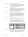
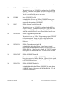
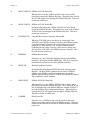
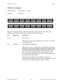
VXI-MXI
User Manual
October 1993 Edition
Part Number 320222-01
© Copyright 1989, 1993 National Instruments Corporation.
All Rights Reserved.
National Instruments Corporate Headquarters
6504 Bridge Point Parkway
Austin, TX 78730-5039
(512) 794-0100
(800) 433-3488 (toll-free U.S. and Canada)
Technical support fax: (512) 794-5678
Branch Offices:
Australia 03 879 9422, Austria 0662 435986, Belgium 02 757 00 20, Canada (Ontario) 519 622 9310,
Canada (Québec) 514 694 8521, Denmark 45 76 26 00, Finland 90 527 2321, France 1 48 65 33 70,
Germany 089 714 50 93, Italy 02 48301892, Japan 03 3788 1921, Netherlands 01720 45761, Norway 03 846866,
Spain 91 640 0085, Sweden 08 730 49 70, Switzerland 056 27 00 20, U.K. 0635 523545
Limited Warranty
The National Instruments MXIbus boards and accessories are warranted against defects in materials and
workmanship for a period of one year from the date of shipment, as evidenced by receipts or other documentation.
National Instruments will, at its option, repair or replace equipment that proves to be defective during the warranty
period. This warranty includes parts and labor.
A Return Material Authorization (RMA) number must be obtained from the factory and clearly marked on the
outside of the package before any equipment will be accepted for warranty work. National Instruments will pay the
shipping costs of returning to the owner parts which are covered by warranty.
National Instruments believes that the information in this manual is accurate. The document has been carefully
reviewed for technical accuracy. In the event that technical or typographical errors exist, National Instruments
reserves the right to make changes to subsequent editions of this document without prior notice to holders of this
edition. The reader should consult National Instruments if errors are suspected. In no event shall National
Instruments be liable for any damages arising out of or related to this document or the information contained in it.
EXCEPT AS SPECIFIED HEREIN, NATIONAL INSTRUMENTS MAKES NO WARRANTIES, EXPRESS OR IMPLIED,
AND SPECIFICALLY DISCLAIMS ANY WARRANTY OF MERCHANTABILITY OR FITNESS FOR A PARTICULAR
PURPOSE . CUSTOMER'S RIGHT TO RECOVER DAMAGES CAUSED BY FAULT OR NEGLIGENCE ON THE PART
OF NATIONAL INSTRUMENTS SHALL BE LIMITED TO THE AMOUNT THERETOFORE PAID BY THE CUSTOMER.
NATIONAL INSTRUMENTS WILL NOT BE LIABLE FOR DAMAGES RESULTING FROM LOSS OF DATA, PROFITS,
USE OF PRODUCTS, OR INCIDENTAL OR CONSEQUENTIAL DAMAGES, EVEN IF ADVISED OF THE POSSIBILITY
THEREOF. This limitation of the liability of National Instruments will apply regardless of the form of action,
whether in contract or tort, including negligence. Any action against National Instruments must be brought within
one year after the cause of action accrues. National Instruments shall not be liable for any delay in performance due
to causes beyond its reasonable control. The warranty provided herein does not cover damages, defects,
malfunctions, or service failures caused by owner's failure to follow the National Instruments installation, operation,
or maintenance instructions; owner's modification of the product; owner's abuse, misuse, or negligent acts; and
power failure or surges, fire, flood, accident, actions of third parties, or other events outside reasonable control.
Copyright
Under the copyright laws, this publication may not be reproduced or transmitted in any form, electronic or
mechanical, including photocopying, recording, storing in an information retrieval system, or translating, in whole
or in part, without the prior written consent of National Instruments Corporation.
Trademarks
Product and company names listed are trademarks or trade names of their respective companies.
Warning Regarding Medical and Clinical Use
of National Instruments Products
National Instruments products are not designed with components and testing intended to ensure a level of reliability
suitable for use in treatment and diagnosis of humans. Applications of National Instruments products involving
medical or clinical treatment can create a potential for accidental injury caused by product failure, or by errors on
the part of the user or application designer. Any use or application of National Instruments products for or involving
medical or clinical treatment must be performed by properly trained and qualified medical personnel, and all
traditional medical safeguards, equipment, and procedures that are appropriate in the particular situation to prevent
serious injury or death should always continue to be used when National Instruments products are being used.
National Instruments products are NOT intended to be a substitute for any form of established process, procedure, or
equipment used to monitor or safeguard human health and safety in medical or clinical treatment.
FCC/DOC Radio Frequency Interference Compliance
This equipment generates and uses radio frequency energy and, if not installed and used in strict accordance with the
instructions in this manual, may cause interference to radio and television reception. This equipment has been tested
and found to comply with the following two regulatory agencies:
Federal Communications Commission
This device complies with Part 15 of the Federal Communications Commission (FCC) Rules for a Class A digital
device. Operation is subject to the following two conditions:
1.
This device may not cause harmful interference in commercial environments.
2.
This device must accept any interference received, including interference that may cause undesired operation.
Canadian Department of Communications
This device complies with the limits for radio noise emissions from digital apparatus set out in the Radio
Interference Regulations of the Canadian Department of Communications (DOC).
Le présent appareil numérique n'émiet pas de bruits radioélectriques dépassant les limites applicables aux appareils
numériques de classe A prescrites dans le réglement sur le brouillage radioélectrique édicté par le ministére des
communications du Canada.
Instructions to Users
These regulations are designed to provide reasonable protection against harmful interference from the equipment to
radio reception in commercial areas. Operation of this equipment in a residential area is likely to cause harmful
interference, in which case the user will be required to correct the interference at his own expense.
There is no guarantee that interference will not occur in a particular installation. However, the chances of
interference are much less if the equipment is installed and used according to this instruction manual.
If the equipment does cause interference to radio or television reception, which can be determined by turning the
equipment on and off, one or more of the following suggestions may reduce or eliminate the problem.
•
Operate the equipment and the receiver on different branches of your AC electrical system.
•
Move the equipment away from the receiver with which it is interfering.
•
Reorient or relocate the receiver's antenna.
•
Be sure that the equipment is plugged into a grounded outlet and that the grounding has not been defeated with
a cheater plug.
Notice to user: Changes or modifications not expressly approved by National Instruments could void the user's
authority to operate the equipment under the FCC Rules.
If necessary, consult National Instruments or an experienced radio/television technician for additional suggestions.
The following booklet prepared by the FCC may also be helpful: How to Identify and Resolve Radio-TV
Interference Problems. This booklet is available from the U.S. Government Printing Office, Washington, DC
20402, Stock Number 004-000-00345-4.
Contents
About This Manual ............................................................................................................... xi
Organization of This Manual ........................................................................................... xi
How to Use This Manual ................................................................................................ xii
Related Documentation ................................................................................................... xii
Customer Communication .............................................................................................. xii
Chapter 1
General Information ..........................................................................................................1-1
Overview ........................................................................................................................1-4
Front Panel Features.......................................................................................................1-5
What Your Kit Should Contain......................................................................................1-6
Optional Equipment .......................................................................................................1-6
Unpacking ......................................................................................................................1-7
Chapter 2
General Description ...........................................................................................................2-1
Electrical Characteristics................................................................................................2-1
VMEbus Modules ..........................................................................................................2-2
VXI-MXI Functional Description..................................................................................2-5
Chapter 3
Configuration and Installation .......................................................................................3-1
Configuring the VXI-MXI .............................................................................................3-1
The Metal Enclosure ..........................................................................................3-4
VXIbus Slot 0.....................................................................................................3-4
VXIbus Logical Address....................................................................................3-6
VMEbus Request Level .....................................................................................3-7
VMEbus Timeout Value ....................................................................................3-8
VMEbus Timeout Chain Position ......................................................................3-10
Interlocked Arbitration Mode ............................................................................3-13
MXIbus System Controller ................................................................................3-14
MXIbus System Controller Timeout..................................................................3-16
MXIbus Fairness Option ....................................................................................3-17
CLK10 Source....................................................................................................3-18
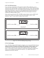
EXT CLK SMB Input/Output ................................................................3-20
INTX CLK10 Mapping..........................................................................3-20
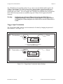
Trigger Input Termination .................................................................................3-22
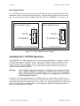
Reset Signal Select .............................................................................................3-23
Installing the VXI-MXI Hardware.................................................................................3-23
MXIbus Termination..........................................................................................3-24
INTX Termination .............................................................................................3-25
Installation Instructions ......................................................................................3-26
Connecting the INTX Cable ..............................................................................3-27
Connecting the MXIbus Cable...........................................................................3-28
System Power Cycling Requirements ................................................................3-30
VMEbus Devices in VXIbus/MXIbus Systems .............................................................3-31
© National Instruments Corporation
v
VXI-MXI User Manual
Contents
Chapter 4
Register Descriptions .........................................................................................................4-1
Register Maps ................................................................................................................4-1
Register Sizes .....................................................................................................4-1
Register Description Format ..............................................................................4-1
Hard and Soft Reset ...........................................................................................4-1
VXIbus Configuration Registers....................................................................................4-4
VXIbus ID Register ...........................................................................................4-4
Device Type Register .........................................................................................4-6
VXIbus Status/Control Register.........................................................................4-7
VXIbus Extender Registers............................................................................................4-9
MODID Register ................................................................................................4-9
Logical Address Window Register ....................................................................4-10
A16 Window Map Register ...............................................................................4-14
A24 Window Map Register ...............................................................................4-18
A32 Window Map Register ...............................................................................4-22
INTX Interrupt Configuration Register .............................................................4-26
INTX Trigger Configuration Register ...............................................................4-27
INTX Utility Configuration Register .................................................................4-28
Subclass Register ...............................................................................................4-30
MXIbus Defined Registers.............................................................................................4-31
MXIbus Status/Control Register ........................................................................4-31
MXIbus Lock Register .......................................................................................4-36
MXIbus IRQ Configuration Register.................................................................4-37
Drive Triggers/Read LA Register ......................................................................4-39
Trigger Mode Selection Register .......................................................................4-41
Interrupt Status/Control Register .......................................................................4-45
Status/ID Register ..............................................................................................4-48
MXIbus Trigger Configuration Register............................................................4-49
Trigger Synchronous Acknowledge Register ....................................................4-50
Trigger Asynchronous Acknowledge Register ..................................................4-50
IRQ Acknowledge Registers..............................................................................4-51
Chapter 5
Programming Considerations ........................................................................................5-1
System Configuration ....................................................................................................5-1
Planning a VXIbus/MXIbus System Logical Address Map ..............................5-1
Base/Size Configuration Format ............................................................5-3
High/Low Configuration Format ...........................................................5-5
Steps to Follow When Planning a System Logical Address Map..........5-5
Worksheets for Planning Your VXIbus/MXIbus Logical Address Map ...........5-13
Alternative Worksheets for Planning Your VXIbus/MXIbus Logical
Address Map ......................................................................................................5-18
Planning a VXIbus/MXIbus System A16 Address Map ...................................5-21
Worksheets for Planning Your VXIbus/MXIbus A16 Address Map ................5-29
Multiframe RM Operation .............................................................................................5-35
Configuring the Logical Address Window ........................................................5-35
Configuring the Logical Address Window Example .............................5-36
Configuring the A24 and A32 Addressing Windows ........................................5-38
System Administration and Initiation ................................................................5-39
VXI-MXI User Manual
vi
© National Instruments Corporation
Contents
Chapter 6
Theory of Operation ..........................................................................................................6-1
VMEbus Address and Address Modifier Transceivers..................................................6-1
VXIbus System Controller Functions ............................................................................6-1
VMEbus Data Transceivers ...........................................................................................6-1
VMEbus Control Signals Transceivers ..........................................................................6-2
VMEbus Requester and Arbiter Circuitry .....................................................................6-2
TTL and ECL Trigger Lines and CLK10 Circuitry .......................................................6-2
SYSFAIL, ACFAIL, and SYSRESET...........................................................................6-3
Interrupt Circuitry ..........................................................................................................6-3
Parity Check and Generation .........................................................................................6-6
A32, A24, A16, and LA Windows.................................................................................6-6
VXI-MXI Configuration Registers ................................................................................6-6
MXIbus Master Mode State Machine ............................................................................6-6
MXIbus Slave Mode State Machine ..............................................................................6-10
MXIbus Address/Data and Address Modifier Transceivers ..........................................6-11
MXIbus System Controller Functions ...........................................................................6-12
MXIbus Control Signals Transceivers ...........................................................................6-12
MXIbus Requester and Arbiter Circuitry.......................................................................6-12
Appendix A
Specifications ........................................................................................................................A-1
Appendix B
Mnemonics Key ...................................................................................................................B-1
Appendix C
VXI-MXI Component Placement ..................................................................................C-1
Removing the Metal Enclosure from the VXI-MXI ......................................................C-1
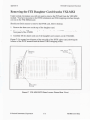
Removing the INTX Daughter Card from the VXI-MXI ..............................................C-3
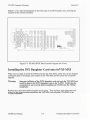
Installing the INTX Daughter Card onto the VXI-MXI ................................................C-4
Appendix D
Connector Descriptions .....................................................................................................D-1
MXIbus Connector.........................................................................................................D-1
INTX Connector ............................................................................................................D-3
Appendix E
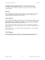
Configuring a Two-Frame System ................................................................................E-1
Configuring VXI-MXIs for a Two-Frame System ........................................................E-1
Configuration Requirements for Two-Frame System....................................................E-6
BTO Unit............................................................................................................E-6
Logical Addresses ..............................................................................................E-6
CLK10 Mapping ................................................................................................E-6
Appendix F
Customer Communication ...............................................................................................F-1
Glossary ...................................................................................................................... Glossary-1
Index ..................................................................................................................................Index-1
© National Instruments Corporation
vii
VXI-MXI User Manual
Contents
Figures
Figure 1-1.
Figure 1-2.
VXI-MXI Interface Module .............................................................................1-2
VXI-MXI Interface Module with INTX Option...............................................1-3
Figure 2-1.
Figure 2-2.
VXI-MXI Block Diagram.................................................................................2-6
VXI-MXI INTX Daughter Card Option Block Diagram .................................2-8
Figure
Figure
Figure
Figure
Figure
Figure
Figure
Figure
Figure
Figure
Figure
Figure
Figure
Figure
Figure
Figure
Figure
Figure
Figure
Figure
Figure
Figure
Figure
Figure
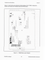
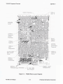
VXI-MXI Parts Locator Diagram.....................................................................3-2
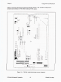
VXI-MXI with INTX Parts Locator Diagram ..................................................3-3
VXIbus Slot 0 Selection ...................................................................................3-4
VXIbus Non-Slot 0 Selection ...........................................................................3-5
Logical Address Selection ................................................................................3-7
VMEbus Requester Jumper Settings ................................................................3-8
VMEbus Timeout Value Selection ...................................................................3-9
VMEbus Timeout; One VXI-MXI in Mainframe ............................................3-10
VMEbus Timeout; Multiple VXI-MXIs in Mainframe ....................................3-11
No VMEbus Timeout; Multiple VXI-MXIs in Mainframe ..............................3-12
Interlocked Arbitration Mode Selection ...........................................................3-14
MXIbus System Controller Selection ...............................................................3-15
MXIbus System Controller Timeout Value Selection ......................................3-16
MXIbus Fair Requester Selection.....................................................................3-17
CLK10 Source Signal Options .........................................................................3-19
EXT CLK SMB Input/Output Setting ..............................................................3-20
INTX CLK10 Mapping Switches .....................................................................3-21
Trigger Input Termination Option Settings ......................................................3-22
Reset Signal Selection Settings ........................................................................3-23
MXIbus System ................................................................................................3-24
MXIbus Terminating Networks........................................................................3-25
INTX Terminator Example...............................................................................3-26
MXIbus Single-Ended Cable Configuration ....................................................3-28
MXIbus Dual-Ended Cable Configuration .......................................................3-29
3-1.
3-2.
3-3.
3-4.
3-5.
3-6.
3-7.
3-8.
3-9.
3-10.
3-11.
3-12.
3-13.
3-14.
3-15.
3-16.
3-17.
3-18.
3-19.
3-20.
3-21.
3-22.
3-23.
3-24.
Figure 4-1.
VXI-MXI Register Map ...................................................................................4-3
Figure
Figure
Figure
Figure
Figure
Figure
Figure
Figure
Figure
Figure
Figure
Figure
Figure
Figure
Figure
Figure
Figure
VXIbus/MXIbus System with Multiframe RM on a PC ..................................5-2
VXIbus/MXIbus System with Multiframe RM in a VXIbus Mainframe.........5-2
Base and Size Combinations ............................................................................5-4
Address Range Allocation for Different Size Values .......................................5-4
Example VXIbus/MXIbus System ...................................................................5-8
Logical Address Map Diagram for Example VXIbus/MXIbus System ...........5-9
Worksheet 1 for Example VXIbus/MXIbus System ........................................5-10
Worksheet 2 for Example VXIbus/MXIbus System ........................................5-11
Worksheet 3 for Example VXIbus/MXIbus System ........................................5-12
Worksheet 4 for Example VXIbus/MXIbus System ........................................5-12
Logical Address Map Example with Alternative Worksheet ...........................5-20
A16 Space Allocations for all Size Values .......................................................5-22
Example VXIbus/MXIbus System ...................................................................5-24
Example A16 Space Address Map ...................................................................5-25
Worksheet 1 for A16 Address Map Example ...................................................5-26
Worksheet 2 for A16 Map Example .................................................................5-27
Worksheet 3 for A16 Map Example .................................................................5-28
5-1.
5-2.
5-3.
5-4.
5-5.
5-6.
5-7.
5-8.
5-9.
5-10.
5-11.
5-12.
5-13.
5-14.
5-15.
5-16.
5-17.
VXI-MXI User Manual
viii
© National Instruments Corporation
Contents
Figure 6-1.
Figure 6-2.
Master to Slave VMEbus/MXIbus Transfers ...................................................6-7
Deadlock Situation............................................................................................6-10
Figure C-1.
Figure C-2.
Figure C-3.
VXI-MXI Parts Locator Diagram.....................................................................C-2
VXI-MXI INTX Parts Locator Diagram (Rear View) .....................................C-3
VXI-MXI INTX Parts Locator Diagram (Front View) ....................................C-4
Figure D-1.
Figure D-2.
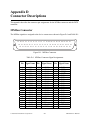
MXIbus Connector ...........................................................................................D-1
INTX Connector ...............................................................................................D-3
Figure
Figure
Figure
Figure
Figure
A Two-Frame VXI System...............................................................................E-1
VXI-MXI in Frame A without INTX ...............................................................E-2
VXI-MXI in Frame B without INTX ...............................................................E-3
VXI-MXI in Frame A with INTX ....................................................................E-4
VXI-MXI in Frame B with INTX ....................................................................E-5
E-1.
E-2.
E-3.
E-4.
E-5.
Tables
Table 2-1.
Table 2-2.
Table 2-3.
VXI-MXI VMEbus Signals ..............................................................................2-1
MXIbus Transceiver Requirements ..................................................................2-2
VXI-MXI VMEbus Compliance Levels...........................................................2-3
Table 3-1.
MXIbus System Power Cycling Requirements ................................................3-30
Table 4-1.
VXI-MXI Register Map ...................................................................................4-2
Table
Table
Table
Table
Table
5-1.
5-2.
5-3.
5-4.
5-5.
Base and Size Combinations ............................................................................5-3
Example VXIbus/MXIbus System Required Logical Addresses .....................5-8
Amount of A16 Space Allocated for all Size Values .......................................5-21
Example VXIbus/MXIbus System Required A16 Space .................................5-25
Logical Address Assignments for Example VXIbus/MXIbus System.............5-36
Table
Table
Table
Table
6-1.
6-2.
6-3.
6-4.
VXI-MXI Addresses for VMEbus Interrupt Levels .........................................6-5
VMEbus to MXIbus Address Modifier Line Map ...........................................6-7
Transfer Responses for VMEbus Address Modifiers .......................................6-8
VMEbus/MXIbus Transfer Size Comparison ..................................................6-9
Table
Table
Table
Table
D-1.
D-2.
D-3.
D-4.
MXIbus Connector Signal Assignments ..........................................................D-1
MXIbus Signal Groupings ................................................................................D-2
INTX Connector Signal Assignments ..............................................................D-3
INTX Signal Groupings....................................................................................D-4
© National Instruments Corporation
ix
VXI-MXI User Manual
About This Manual
The VXI-MXI User Manual describes the functional, physical, and electrical aspects of the
VXI-MXI and contains information concerning its operation and programming.
Organization of This Manual
The VXI-MXI User Manual is organized as follows:
•
Chapter 1, General Information, describes the VXI-MXI features, lists the contents of your
VXI-MXI kit, and explains how to unpack the VXI-MXI kit.
•
Chapter 2, General Description, contains the physical and electrical specifications for the
VXI-MXI and describes the characteristics of key components.
•
Chapter 3, Configuration and Installation, describes the configuration and installation of the
VXI-MXI hardware.
•
Chapter 4, Register Descriptions, contains detailed descriptions of the VXI-MXI registers,
which are used to configure and control the module's operation.
•
Chapter 5, Programming Considerations, explains important considerations for programming
the VXI-MXI and configuring a system using VXI-MXIs.
•
Chapter 6, Theory of Operation, contains a functional overview of the VXI-MXI board and
explains the operation of each functional block making up the VXI-MXI.
•
Appendix A, Specifications, lists the specifications of the VXI-MXI.
•
Appendix B, Mnemonics Key, contains an alphabetical listing of all mnemonics used in this
manual.
•
Appendix C, VXI-MXI Component Placement, contains information on the component
placement and describes how to remove the metal enclosure and INTX daughter card.
•
Appendix D, Connector Descriptions, describes the connector pin assignments for the
MXIbus connector.
•
Appendix E, Configuring a Two-Frame System, describes how to configure a system
containing two mainframes linked by VXI-MXI modules.
•
Appendix F, Customer Communication, contains forms you can use to request help from
National Instruments or to comment on our products and manuals.
•
The Glossary contains an alphabetical list and description of terms used in this manual,
including abbreviations, acronyms, metric prefixes, and symbols.
•
The Index contains an alphabetical list of key terms and topics in this manual, including the
page where you can find each one.
© National Instruments Corporation
xi
VXI-MXI User Manual
About This Manual
How to Use This Manual
If you will be installing your VXI-MXI into a system with a VXIbus Resource Manager, you
only need to read Chapters 1 through 3 of this manual. If you have more than two VXI-MXIs
extending your system, you will find useful system configuration information in Chapter 5.
Appendix E is a quick reference for users who have a system containing two mainframes linked
by VXI-MXI modules. If you are writing your own VXIbus Resource Manager routines, you
can find programming information and descriptions of the VXI-MXI hardware in Chapters 4
through 6.
Related Documentation
The following manuals contain information that you may find helpful as you read this manual:
•
IEEE Standard for a Versatile Backplane Bus: VMEbus, ANSI/IEEE Standard 1014-1987
•
Multisystem Extension Interface Bus Specification, Version 1.2 (part number 340007-01)
•
VXIbus System Specification, Revision 1.4, VXIbus Consortium (available from National
Instruments, part number 350083-01)
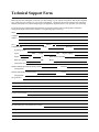
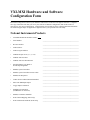
Customer Communication
National Instruments wants to receive your comments on our products and manuals. We are
interested in the applications you develop with our products, and we want to help if you have
problems with them. To make it easy for you to contact us, this manual contains comment and
configuration forms for you to complete. These forms are in Appendix F, Customer
Communication, at the end of this manual.
VXI-MXI User Manual
xii
© National Instruments Corporation
Chapter 1
General Information
This chapter describes the VXI-MXI features, lists the contents of your VXI-MXI kit, and
explains how to unpack the VXI-MXI kit.
The VXI-MXI interface is a C-size extended class mainframe extender for the VXIbus (VMEbus
Extensions for Instrumentation). It extends the VXIbus architecture outside a VXIbus
mainframe via the MXIbus (Multisystem Extension Interface bus). A VXIbus mainframe
equipped with a VXI-MXI can be transparently connected to other MXIbus devices such as other
VXIbus mainframes, MXIbus instruments, or MXIbus-equipped personal computers. The
VXI-MXI interface module uses address mapping to transparently translate bus cycles on the
VXIbus system bus (VMEbus) to the MXIbus and vice versa.
The VXI-MXI is housed in a metal enclosure to improve EMI performance and to provide easy
handling. Because the enclosure includes cut-outs to facilitate changes to switch and jumper
settings, it should not be necessary to remove it under most circumstances.
The VXI-MXI is available with an Interrupt and Timing Extension (INTX) daughter card option.
If you ordered this option, the INTX card is already installed on your VXI-MXI. The INTX
daughter card is a full-length daughter card that plugs into the two daughter card connectors on
the VXI-MXI. Because this manual describes the VXI-MXI with and without this option, you
can find information on the INTX card throughout this manual. Refer also to Appendix C,
VXI-MXI Component Placement, for information on removing and reinstalling the INTX
daughter card. This appendix also contains silkscreens of the VXI-MXI and the INTX card.
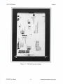
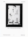
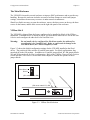
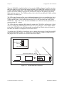
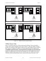
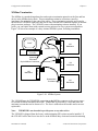
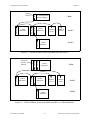
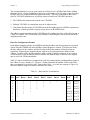
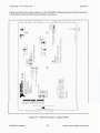
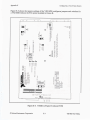
Figure 1-1 shows the enclosed VXI-MXI interface module without the INTX option. Figure 1-2
shows the enclosed VXI-MXI interface module with the INTX option.
© National Instruments Corporation
1-1
VXI-MXI User Manual
General Information
Chapter 1
Overview
The VXI-MXI is an extended class Register-Based VXIbus device with optional Slot 0 capability
so that it can reside in any slot in a C-size or D-size VXIbus chassis. The VXI-MXI converts
A32, A24, A16, D32, D16, and D08(EO) VXIbus bus cycles into MXIbus bus cycles and vice
versa. The VXI-MXI has four address windows that map into and out of the VXIbus mainframe.
These four windows represent the three VMEbus address spaces (A32, A24, and A16) plus a
dedicated window for mapping the VXIbus configuration space (the upper 16 kilobytes of A16
space).
The MXIbus is a multidrop system bus that connects multiple devices at the hardware bus level
in a software-transparent manner. Multiple VXIbus mainframes with VXI-MXI interfaces can
be connected to form a single multiframe VXIbus system. An external PC with a MXIbus
interface can also be connected to a VXIbus mainframe with a VXI-MXI. This configuration
makes the PC appear to be embedded on a VXIbus module that is plugged into the VXIbus
mainframe.
Multiple MXIbus devices are tightly coupled by mapping together portions of each device's
address space and locking the internal hardware bus cycles to the MXIbus. The window address
circuitry on each MXIbus device monitors internal local bus cycles to detect bus cycles that map
across the MXIbus. Similarly, external MXIbus cycles are monitored to detect MXIbus cycles
that map into the VXIbus system. MXIbus devices can operate in parallel at full speed over their
local system bus and need to synchronize operation with another device only when addressing or
being addressed by a resource located on another MXIbus device. The MXIbus device
originating the transaction must gain ownership of both the MXIbus and the local bus in the
target MXIbus device. All hardware bus cycles are then coupled across the MXIbus and local
buses before the transfer completes.
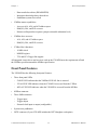
The VXI-MXI has the following features:
•
•
•
•
•
•
•
•
•
Interfaces the VXIbus to the MXIbus (32-bit Multisystem eXtension Interface bus)
Extends VXIbus to multiple mainframes, external MXIbus-equipped instruments, and
external MXIbus-equipped personal computers (PCs)
Allows multiple VXIbus mainframes to appear as a single VXIbus system
Provides integrated block mode for high-performance data transfers
Supports dynamic configuration of VXIbus devices
Provides optional interlocked bus operation for prevention of deadlock conditions
Includes daughter card connector scheme giving additional functionality for optional
daughter cards
Is fully compatible with VXIbus and MXIbus specifications
Has no restrictions on Commander/Servant hierarchy or physical location of devices
The VXI-MXI generates all the support signals required by the VMEbus:
•
VMEbus System Controller functions:
–
–
16 MHz system clock driver
VME bus timeout (BTO)
VXI-MXI User Manual
1-4
© National Instruments Corporation
Chapter 1
–
–
–
•
Access to A16, A24, and A32 address space
D08(EO), D16, and D32 accesses
Release-on-Request bus requester (jumper-selectable arbitration level)
VMEbus slave accesses:
–
–
•
Data transfer bus arbiter (PRI ARBITER)
Interrupt acknowledge daisy-chain driver
Pushbutton system reset switch
VMEbus master capabilities:
–
–
–
•
General Information
A16, A24, and A32 address space
D08(EO), D16, and D32 accesses
VXIbus Slot 0 functions:
–
–
–
10 MHz clock
MODID register
TTL and ECL Trigger line support
All integrated circuit drivers and receivers used on the VXI-MXI meet the requirements of both
the VMEbus specification and the MXIbus specification.
Front Panel Features
The VXI-MXI has the following front panel features:
•
Three front panel LEDs
–
–
–
FAILED LED indicates that the VMEbus SYSFAIL line is asserted.
VXI ACCESS LED indicates when the VXI-MXI is accessed from the VXIbus.
MXI ACCESS LED indicates when the VXI-MXI is accessed from the MXIbus.
•
MXIbus connector
•
Three SMB connectors
–
–
–
Trigger input
Trigger output
External clock input or output (configurable)
•
System reset pushbutton
•
INTX connector (if your VXI-MXI includes the INTX daughter card option)
© National Instruments Corporation
1-5
VXI-MXI User Manual
General Information
Chapter 1
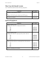
What Your Kit Should Contain
Your VXI-MXI kit should contain the following components:
Component
Part Number
Standard VXI-MXI Interface Module
or
Enhanced VXI-MXI Interface Module with INTX option
181045-01
VXI-MXI User Manual
320222-01
181045-02
Optional Equipment
Equipment
Part Number
Type M1 MXIbus Cables
Straight-point connector to straight-point connector:
– 1m
– 2m
– 4m
– 8m
– 20 m
180758-01
180758-02
180758-04
180758-08
180758-20
Type M2 MXIbus Cables
Straight-point connector to right-angle daisy-chain connector:
– 1m
– 2m
– 4m
– 8m
– 20 m
180760-01
180760-02
180760-04
180760-08
180760-20
Type M3 MXIbus Cables
Right-angle point connector to right-angle daisy-chain connector:
– 1m
– 2m
– 4m
– 8m
– 20 m
180761-01
180761-02
180761-04
180761-08
180761-20
MXIbus Terminating Pac (External)
VXI-MXI User Manual
180780-01
1-6
© National Instruments Corporation
Chapter 1
General Information
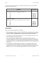
The following optional equipment is also available and may be necessary if your VXI-MXI
includes the INTX daughter card.
Equipment
Part Number
Type INTX1 Cables
Straight-point connector to straight-point connector:
– 1m
– 2m
– 4m
– 8m
– 20 m
180980-01
180980-02
180980-04
180980-08
180980-20
Type INTX2 Cables
Right-angle point connector to right-angle daisy-chain connector:
– 1m
– 2m
– 4m
– 8m
– 20 m
180982-01
180982-02
180982-04
180982-08
180982-20
Unpacking
Follow these steps when unpacking your VXI-MXI:
1. Before attempting to configure or install the VXI-MXI, inspect the shipping container and its
contents for damage. If damage appears to have been caused in shipment, file a claim with
the carrier. Retain the packing material for possible inspection and/or for reshipment.
2. Verify that the pieces contained in the package you received match the kit parts list. Do not
remove the board from its bag at this point.
3. Your VXI-MXI module is shipped packaged in an antistatic plastic bag to prevent
electrostatic damage to the module. Several components on the module can be damaged by
electrostatic discharge. To avoid such damage while handling the module, touch the plastic
bag to a metal part of your grounded VXIbus mainframe chassis before removing the module
from the bag.
4. As you remove the VXI-MXI module from its bag, be sure to handle it only by its edges.
Avoid touching any of the IC components or connectors. Inspect the module for loose
components or any other sign of damage. Notify National Instruments if the module appears
damaged in any way. Do not install a damaged module into your VXIbus mainframe.
© National Instruments Corporation
1-7
VXI-MXI User Manual
Chapter 2
General Description
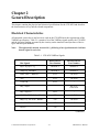
This chapter contains the physical and electrical specifications for the VXI-MXI and describes
the characteristics of key interface board components.
Electrical Characteristics
All integrated circuit drivers and receivers used on the VXI-MXI meet the requirements of the
VMEbus specification. Table 2-1 contains a list of the VMEbus signals used by the VXI-MXI
and the electrical loading presented by the circuitry on the interface board (in terms of device
types and their part numbers).
Note:
Throughout this manual, an asterisk (*) following a bus signal mnemonic indicates
that the signal is active low.
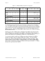
Table 2-1. VXI-MXI VMEbus Signals
Driver Device
Part Number
Receiver Device
Part Number
D[31–0], A[31–1],
ALS645–1
ALS645–1
AM[5–0], LWORD
ALS646–1
ALS646–1
DS0*, DS1*, WRITE*
F125
ALS244
AS*
F125
ALS240
SYSCLK
F125
–
–
HCT273,
GAL16V8
BG[3-0]OUT*
LS32
–
BBSY*, SYSFAIL*, ACFAIL*
F38
ALS240
BR[3-0]*, DTACK*, BERR*
F38
ALS244
AS760
ALS244
F38
–
Bus Signals
BG[3-0]IN*
SYSRESET*
IACK*
(continues)
© National Instruments Corporation
2-1
VXI-MXI User Manual
General Description
Chapter 2
Table 2-1. VXI-MXI VMEbus Signals (Continued)
Bus Signals
Driver Device
Part Number
Receiver Device
Part Number
–
LS540
GAL20V8
–
AS760,
LS145
LS540
IACKIN*
IACKOUT*
IRQ[7-1]*
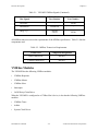
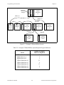
All MXIbus transceivers meet the requirements of the MXIbus specification. Table 2-2 lists the
components used.
Table 2-2. MXIbus Transceiver Requirements
Transceivers
Component Designation
Data Transceivers
DS3862
Control Transceivers
DS3662
VMEbus Modules
The VXI-MXI has the following VMEbus modules:
•
VMEbus Requester
•
VMEbus Master
•
VMEbus Slave
•
Interrupter
•
IACK Daisy-Chain Driver
When the VXI-MXI is configured as a VXIbus Slot 0 device, it also has the following VMEbus
modules:
•
VMEbus Timer
•
Arbiter
•
System Clock Driver
VXI-MXI User Manual
2-2
© National Instruments Corporation
Chapter 2
General Description
The VXI-MXI does not support the following VMEbus modules:
•
Serial Clock Driver
•
Power Monitor
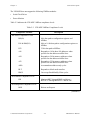
Table 2-3 indicates the VXI-MXI VMEbus compliance levels.
Table 2-3. VXI-MXI VMEbus Compliance Levels
Compliance Notation
Description
Bus Slave Compliance Levels
D08(O)
8-bit data path to configuration registers and
MXIbus
D16 & D08(EO)
8-bit or 16-bit data path to configuration registers or
MXIbus
D32
32-bit data path to MXIbus
A16
Responds to 16-bit short I/O addresses when
specified on the address modifier lines
A24
Responds to 24-bit memory addresses when
specified on the address modifier lines
A32
Responds to 32-bit memory addresses when
specified on the address modifier lines
ADO
Accommodates address-only cycles
BLT
Responds to block mode transfers
RMW
Can accept Read-Modify-Write cycles
DTB Arbiter Compliance Level
PRI
Monitors BR3* through BR0* and drives
BG3OUT* through BG0OUT* and BCLR*
DTB Requester Compliance Level
ROR
Release-on-Request
(continues)
© National Instruments Corporation
2-3
VXI-MXI User Manual
General Description
Chapter 2
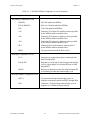
Table 2-3. VXI-MXI VMEbus Compliance Levels (Continued)
Compliance Notation
Description
Bus Master Compliance Levels
D08(EO)
8-bit data path from MXIbus
D16 & D08(EO)
8-bit or 16-bit data path from MXIbus
D32
32-bit data path from MXIbus
A16
Generates 16-bit short I/O addresses when specified
by the MXIbus address modifier lines
A24
Generates 24-bit memory addresses when specified
by the MXIbus address modifier lines
A32
Generates 32-bit memory addresses when specified
by the MXIbus address modifier lines
BLT
Generates block mode transfers when specified
by the MXIbus address modifier lines
RMW
Can generate Read-Modify-Write cycles
Interrupter Compliance Levels
I(7-1)
Can generate an interrupt request on interrupt lines
IRQ7 through IRQ1
D16 & D32
Responds to 16-bit and 32-bit interrupt acknowledge
cycles by providing a 16-bit Status/ID byte on D00
through D15
ROAK
Releases its interrupt request line when its Status/ID
is read during an interrupt acknowledge cycle
Interrupt Handler Compliance Levels
IH(7-1)
Can generate interrupt acknowledge cycles in
response to interrupt requests on IRQ7 through IRQ1
D16
Generates a 16-bit interrupt acknowledge cycle in
response to a VMEbus interrupt request
VXI-MXI User Manual
2-4
© National Instruments Corporation
Chapter 2
General Description
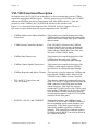
VXI-MXI Functional Description
In simplest terms, the VXI-MXI can be thought of as a bus translator that converts VXIbus
signals into appropriate MXIbus signals. From the perspective of the MXIbus, the VXI-MXI
implements a MXIbus interface to communicate with other MXIbus devices. From the
perspective of the VMEbus, the VXI-MXI is an interface to the outside world.
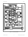
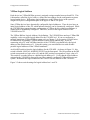
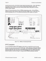
Figure 2-1 is a functional block diagram of the VXI-MXI. Refer to Chapter 6, Theory of
Operation for more details about the major components of the VXI-MXI.
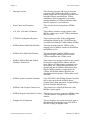
•
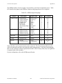
VMEbus Address and Address Modifiers These transceivers control the direction of the
Transceivers
VMEbus address lines and latch the status of the
address lines on the falling edge of the VMEbus
address strobe.
•
VXIbus System Controller Functions
If the VXI-MXI is selected as the VMEbus
System Controller, this circuitry generates the
16 MHz system clock, provides the VMEbus
arbiter and the VMEbus Bus Timer Unit, and
drives the VXIbus CLK10 signal.
•
VMEbus Data Transceivers
These transceivers control the direction of the
VMEbus data lines and meet VMEbus
specifications for timing and signal loading.
•
VMEbus Control Signals Transceivers
These transceivers control the direction of the
VMEbus control signals and meet VMEbus
specifications for timing and signal loading.
•
VMEbus Requester and Arbiter Circuitry This circuitry is used to request the VMEbus and
to provide the VMEbus arbiter function if the
VXI-MXI is the VMEbus System Controller.
•
TTL and ECL Trigger Lines and
CLK10 Circuitry
This circuitry controls the sending and receiving
of the TTL and ECL Trigger lines to and from the
SMB connectors on the front panel and from
onboard registers. This logic also controls
whether the VXI-MXI receives the CLK10 signal
from another VXIbus device, or drives the signal
from an onboard 10 MHz oscillator or from an
external signal connected to the EXT CLK SMB
connector on the front panel.
•
SYSFAIL, ACFAIL, and SYSRESET
Through this circuitry, the VMEbus signals
SYSFAIL, ACFAIL and SYSRESET connect to
the corresponding signals on the daughter card
connections. These three signals can also be
individually enabled to generate a VMEbus
interrupt. With control bits in onboard registers,
SYSFAIL and SYSRESET can also be driven on
the VMEbus backplane.
© National Instruments Corporation
2-5
VXI-MXI User Manual
General Description
Chapter 2
Daughter Card Connection
IRQ7-1
SYSFAIL*
SYSRESET*
ACFAIL*
SYSFAIL, ACFAIL,
SYSRESET Logic
IRQ*
Interrupt
Circuitry
VMEbus IRQ7-1
A32
Window
MXIbus
Address/Dat
a and
Address
Modifiers
Transceivers
A24
Window
VXIbus
VXIbus
System
Controller
Functions
D31-0
VMEbus
Data
Transceivers
A16
Window
LA
Window
AM4-0
MXIbus
System
Controller
Functions
VXI-MXI
Configuration
Registers
VMEbus
Control Signals
Transceivers
MXIbus
Master Mode
State
Machine
MXIbus
Control Signals
Transceivers
VMEbus
Requester and
Arbiter Circuitry
MXIbus
Slave Mode
State
Machine
MXIbus
Requester and
Arbiter Circuitry
TTL Trigger Lines 7-0
ECL Trigger Lines 1-0
CLK10
AD31-0
MXIbus
VMEbus
AM5-0 Address and
Address
Modifiers
A31-1
Transceivers
PAR
Parity
Check and
Generation
TRG OUT
TTL and ECL
Trigger Lines
and
CLK10 Circuitry
TRG IN
EXT CLK
Front
Panel
SMBs
Figure 2-1. VXI-MXI Block Diagram
VXI-MXI User Manual
2-6
© National Instruments Corporation
Chapter 2
General Description
•
Interrupt Circuitry
This circuitry generates and receives interrupt
requests on the VMEbus, the MXIbus, and on
boards plugged into the daughter card connectors.
Interrupt requests routed between VXIbus
mainframes can be transparently serviced by
interrupt handlers in VXIbus mainframes other
than the requester's own mainframe.
•
Parity Check and Generation
This circuitry checks and generates MXIbus
parity.
•
A32, A24, A16 and LA Windows
These address windows assign portions of the
MXIbus address space to the VXIbus mainframe
and vice versa.
•
VXI-MXI Configuration Registers
These registers provide all the configuration
information required by the VXI-MXI and are
accessible from both the VXIbus and the MXIbus.
•
MXIbus Master Mode State Machine
This state machine converts VXIbus cycles
mapped out of a MXIbus window to the MXIbus
into MXIbus cycles.
•
MXIbus Slave Mode State Machine
This state machine converts MXIbus cycles
mapped through a MXIbus window into the
VXIbus mainframe into VXIbus cycles.
•
MXIbus Address/Data and Address
Modifiers Transceivers
These transceivers and associated circuitry control
the direction of the MXIbus address and data
lines. When a VXIbus transfer is mapped out to
the MXIbus, the VXIbus address/data lines are
multiplexed into the MXIbus address/data lines.
When a MXIbus transfer is mapped into the
VXIbus, the MXIbus address/data lines are
demultiplexed into separate VXIbus address and
data lines.
•
MXIbus System Controller Functions
If the VXI-MXI is the MXIbus System Controller,
this circuitry provides the MXIbus arbiter,
interrupt daisy-chain generation, and the MXIbus
System Controller timeout logic.
•
MXIbus Control Signals Transceivers
These transceivers control the direction of the
MXIbus control signals.
•
MXIbus Requester and Arbiter Circuitry This circuitry is used to request the MXIbus when
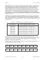
a VXIbus transfer is mapped into a MXIbus
window.
•
Daughter Card Connection
© National Instruments Corporation
The two daughter card connectors can be used to
add additional functionality to the VXI-MXI in
the form of plug-in daughter cards.
2-7
VXI-MXI User Manual
General Description
Chapter 2
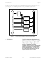
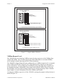
The following information applies only to VXI-MXI kits that include the INTX daughter card
option. Figure 2-2 is a block diagram of the circuitry of the INTX daughter card.
VX I-MXI CONNECTION
INTX
Registers
Trigger
Control
INTX
Interrupt Control
System Resets
Control
CLK10 Control
Figure 2-2. VXI-MXI INTX Daughter Card Option Block Diagram
•
INTX Registers
VXI-MXI User Manual
The INTX card has three onboard registers that
reside in the VXI-MXI configuration space: the
INTX Interrupt Configuration Register, the INTX
Trigger Configuration Register, and the INTX
Utility Configuration Register. These registers
configure the mapping of the VMEbus interrupt
lines, the VXIbus trigger lines and the
SYSRESET, SYSFAIL, and ACFAIL lines to and
from the INTX connector. The INTX card also
drives the Extended Device Type Class field in
the VXIbus Status/Control Register when that
register is accessed on the VXI-MXI.
2-8
© National Instruments Corporation
Chapter 2
•
Interrupt Control
General Description
The interrupt control logic maps the VMEbus
interrupt lines to and from the corresponding
INTX interrupt lines. In conjunction with the
VXI-MXI circuitry, the interrupt requests routed
between VXIbus mainframes through the INTX
connector can be transparently serviced by
interrupt handlers in VXIbus mainframes other
than the mainframe from which the request was
generated. This process takes advantage of
transparent MXIbus interrupt acknowledge cycles.
When an interrupt request received from across
the INTX is driven on the corresponding VMEbus
interrupt line, an interrupt handler in the receiving
VXIbus mainframe generates an interrupt
acknowledge cycle for that interrupt request. This
interrupt acknowledge cycle is transparently
converted into a MXIbus interrupt acknowledge
cycle for that interrupt request level. Similarly,
when a VMEbus interrupt line is driven out of the
VXIbus mainframe across the INTX connection,
an interrupt handler in another VXIbus mainframe
can generate an interrupt acknowledge cycle to
handle that interrupt. The VXI-MXI in the
requesting mainframe recognizes that the MXIbus
interrupt acknowledge cycle is for the request it is
driving and converts the cycle into a VMEbus
interrupt acknowledge cycle that can service the
VMEbus interrupt requester.
•
Trigger Control
The trigger control logic maps the VXIbus TTL
trigger lines to and from the corresponding INTX
trigger lines.
•
System Resets Control
The system resets control circuitry maps the
VMEbus signals SYSRESET, SYSFAIL, and
ACFAIL to the corresponding signals on the
INTX connection.
•
CLK10 Control
The CLK10 control circuitry routes the VMEbus
10 MHz signal to and from the INTX connection.
The configuration of the CLK10 mapping is
controlled by three switches on the INTX
daughter card. Refer to the INTX CLK10
Mapping section of Chapter 3, Configuration and
Installation, for instructions on configuring these
switches.
© National Instruments Corporation
2-9
VXI-MXI User Manual
Chapter 3
Configuration and Installation
This chapter describes the configuration and installation of the VXI-MXI.
Configuring the VXI-MXI
Before installing the VXI-MXI in the VXIbus mainframe, configure the VXI-MXI to suit the
needs for your VXIbus system. The VXI-MXI module contains jumpers, switches, and slide
switches that you can use to configure the following options:
•
VXIbus Slot 0
•
VXIbus Logical Address
•
VMEbus Request Level
•
VMEbus Timeout Value
•
VMEbus Timeout Chain Position
•
Interlocked Arbitration Mode
•
MXIbus System Controller
•
MXIbus System Controller Timeout
•
MXIbus Fairness Option
•
CLK10 Source
•
EXT CLK SMB Input/Output
•
Trigger Input Termination
•
Reset Signal Select
If your VXI-MXI module includes the INTX daughter card option, you can also configure the
following option:
•
CLK10 Mapping
© National Instruments Corporation
3-1
VXI-MXI User Manual
Configuration and Installation
Chapter 3
The Metal Enclosure
The VXI-MXI is housed in a metal enclosure to improve EMC performance and to provide easy
handling. Because the enclosure includes cut-outs to facilitate changes to switch and jumper
settings, it should not be necessary to remove it under normal circumstances.
Should you find it necessary to open the enclosure, remove the three screws on the top, the three
screws on the bottom, and the three screws on the right side panel of the enclosure.
VXIbus Slot 0
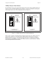
The VXI-MXI is shipped from the factory configured to be installed in Slot 0 of the VXIbus
mainframe. If another device is already in Slot 0, you must decide which device will be the Slot
0 device and reconfigure the other device for Non-Slot 0 use.
Warning:
Do not install a device configured for Slot 0 into another slot without first
reconfiguring it for Non-Slot 0 use. Doing so could result in damage to the
Non-Slot 0 device, the VXIbus backplane, or both.
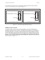
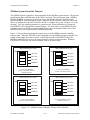
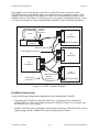
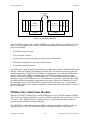
Figure 3-3 shows the default configuration settings for the VXI-MXI installed as the Slot 0
device. The position of slide switches S1 and S8 must match. For Slot 0 configuration, they
must both be in the ON position. In addition to S1 and S8, jumper block W7 and jumper blocks
W9 and W10 must be set for Slot 0 configuration. Refer to the VMEbus Timeout Chain Position
section and the CLK10 Source section later in this chapter to examine the options for these
jumper blocks.
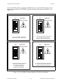
S1
Non-Slot 0
Slot 0
No
lo
n-S
Sl
ot
0
t0
(S1 must match S8)
(S8 must match S1) S8
Figure 3-3. VXIbus Slot 0 Selection
VXI-MXI User Manual
3-4
© National Instruments Corporation
Chapter 3
Configuration and Installation
When the VXI-MXI is installed in Slot 0, it becomes the VMEbus System Controller, meaning
that it has VMEbus Data Transfer Bus Arbiter capability (PRI ARBITER) and that it drives the
16 MHz VMEbus system clock. The VMEbus Data Transfer Bus Arbiter circuitry accepts bus
requests on all four VMEbus request levels, prioritizes the requests, and grants the bus to the
highest priority requester. The VMEbus system clock is driven by an onboard 16 MHz oscillator
with a 50% ±5% duty cycle.
The VXIbus specification defines several additional functions for devices installed in the Slot 0
position. A Slot 0 device must implement a 16-bit MODID register to control and monitor the
VXIbus MODID lines. Slot 0 cards must also have 16.9 k pull-up resistors on each VXIbus
MODID line. If the card is not in Slot 0, the MODID0 line on that card must be pulled down to
ground with an 825 resistor.
The VXIbus Resource Manager (RM) identifies whether the VXI-MXI is configured as a Slot 0
device by reading the VXIbus Model Code in the Device Type Register. If the VXIbus Model
Code for the VXI-MXI is hex 00FE, the module is configured as a Slot 0 device; if the code is
hex 08FE, the module is configured as a Non-Slot 0 device.
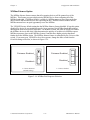
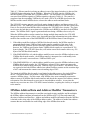
To configure the VXI-MXI as a Non-Slot 0 device, change slide switches S1 and S8 to the OFF
positions as depicted in Figure 3-4. Remember to also change the settings of jumper block W7
and jumper blocks W9 and W10 as described later in this chapter.
S1
Non-Slot 0
Slot 0
No
S
n-
o
Sl
t0
lot
0
(S1 must match S8)
(S8 must match S1) S8
Figure 3-4. VXIbus Non-Slot 0 Selection
© National Instruments Corporation
3-5
VXI-MXI User Manual
Configuration and Installation
Chapter 3
VXIbus Logical Address
Each device in a VXIbus/MXIbus system is assigned a unique number between 0 and 254. This
8-bit number, called the logical address, defines the base address for the configuration registers
located on the device. With unique logical addresses, each VXIbus device in the system is
assigned 64 bytes of configuration space in the upper 16 KB of A16 space.
Some VXIbus devices have dynamically configurable logical addresses. These devices have an
initial logical address of hex FF, which indicates that they can be dynamically configured. While
the VXI-MXI does support dynamic configuration of VXIbus devices within its mainframe, it
cannot itself be dynamically configured. Therefore, do not set the logical address for the
VXI-MXI to hex FF.
The VXIbus RM has Logical Address 0 by definition. The VXI-MXI does not have VXIbus RM
capability, so do not set the logical address for the VXI-MXI to 0. If you are configuring a
multiple-mainframe VXIbus/MXIbus system, refer to Chapter 5, Programming Considerations,
for instructions on planning a VXIbus/MXIbus system logical address map. If you are
connecting only a PC with a MXIbus interface to the VXI-MXI, you should leave the logical
address at the default setting of 1. Using this setting, you can install devices with all other
possible logical addresses in the VXIbus mainframe.
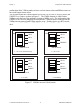
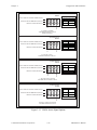
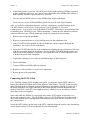
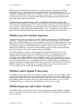
An 8-bit DIP switch selects the logical address for the VXI-MXI. As shown in Figure 3-1, this
switch is labeled LOGICAL ADDRESS SWITCH on the front panel. The ON position on the DIP
switch corresponds to a logic value of 0, and the OFF position corresponds to a logic value of 1.
This switch is set at the factory to a default logical address of 1. Verify that the logical address
assigned to the VXI-MXI is not used by any other statically configured VXIbus device in your
system. Remember that logical addresses hex 0 and FF are not allowed for the VXI-MXI.
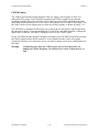
Figure 3-5 shows switch settings for logical address hex 1 and C0.
VXI-MXI User Manual
3-6
© National Instruments Corporation
Chapter 3
Configuration and Installation
LOGICAL ADDRESS
SWITCH
OFF
ON
1
2
OFF
1
2
3
4
5
6
7
8
3
4
Shown at
Default setting
of Logical Address 1
5
6
7
8
Push this side down for logic 0
Push this side down for logic 1
a. Switch Setting to Default Setting Logical Address
LOGICAL ADDRESS
SWITCH
OFF
ON
1
2
OFF
3
4
5
6
7
8
1
2
3
4
5
6
7
8
Shown at
Default setting
of Logical Address 1
Push this side down for logic 0
Push this side down for logic 1
b. Switch Set to Logical Address hex C0
Figure 3-5. Logical Address Selection
VMEbus Request Level
The VXI-MXI uses one of the four VMEbus request levels to request use of the VMEbus Data
Transfer Bus (DTB). The VXI-MXI requests use of the DTB whenever an external MXIbus
device attempts a transfer that maps into the VXIbus mainframe.
The VXI-MXI is shipped from the factory configured to use VMEbus request level 3, as required
in the VXIbus specification. Request level 3 is the highest priority request level and request
level 0 is the lowest. You can change the VXI-MXI to use any of the other three request levels
by changing the jumper configuration on the jumper blocks labeled VMEbus Request Level on
the front panel. You may want to change request levels to change the priority of the VXI-MXI
request signal. For more information, refer to the VMEbus specification.
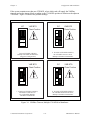
To change the VMEbus request level of the VXI-MXI, rearrange the jumpers on the pin arrays as
shown in Figure 3-6.
© National Instruments Corporation
3-7
VXI-MXI User Manual
VMEbus Request Level
•
•
•
•
•
•
•
•
•
•
•
•
•
•
•
•
•
•
•
•
•
•
•
•
•
•
•
•
•
•
•
•
•
•
•
•
•
•
•
•
•
•
•
•
•
•
•
•
•
•
•
•
•
•
b. Level 2 Requester
•
•
•
VMEbus Request Level
a. Level 3 Requester (default)
•
•
•
VMEbus Request Level
•
•
•
•
•
•
•
•
•
•
•
•
•
•
•
•
•
•
•
•
•
•
•
•
•
•
•
•
•
•
•
•
•
Chapter 3
•
•
•
Configuration and Installation
VMEbus Request Level
c. Level 1 Requester
d. Level 0 Requester
Figure 3-6. VMEbus Requester Jumper Settings
VMEbus Timeout Value
When a VXI-MXI is installed in a VXIbus mainframe, the VME Bus Timeout Unit (BTO)
circuitry for the VXIbus mainframe must be on the VXI-MXI. If there are multiple VXI-MXI
interfaces in a mainframe, the BTO must be enabled on one of them and they must be in adjacent
slots. In the case of multiple VXI-MXIs, it is recommended that the BTO be enabled on the
VXI-MXI that is installed in Slot 0. The BTO monitors the current bus cycle and asserts the bus
error (BERR) signal if a data transfer acknowledge (DTACK) or BERR is not received from the
selected slave within the given amount of time after data strobe (DS1 or DS0) becomes active.
Whenever a MXIbus transfer into or out of the VXI-MXI occurs, the VMEbus timeout on the
VXI-MXI is disabled and the MXIbus System Controller BTO monitors the transfer. This
VXI-MXI User Manual
3-8
© National Instruments Corporation
Chapter 3
Configuration and Installation
configuration allows VXIbus transfers to have short bus timeout values and MXIbus transfers to
have much longer timeout values.
You can either disable the VMEbus timeout value or set it to 100, 200, or 400 µs by moving the
VME BTO Level jumper, as shown in Figure 3-7. The VMEbus timeout is disabled when a
VMEbus cycle maps out of the mainframe, initiating a MXIbus cycle. The configuration of the
VME BTO Chain Position jumper block selects how the VXIbus local bus is used to disable the
VMEbus timeout when outward MXIbus transfers occur. If another device has a BTO module,
remember to enable the BTO on the VXI-MXI and to disable the VMEbus BTO on the other
device.
VME BTO Level
VME BTO Level
•
•
•
•
100 µs
•
200 µs
•
400 µs
•
•
•
DISABLE
DISABLE
W6
•
•
400 µs
400 µs
b. 200 µs BTO
•
•
•
200 µs
•
•
•
•
•
100 µs
200 µs
VME BTO Level
a. 100 µs BTO (Default Setting)
W6
100 µs
•
•
DISABLE
•
•
400 µs
•
•
200 µs
W6
•
•
100 µs
•
•
•
•
•
W6
DISABLE
VME BTO Level
c. 400 µs BTO
d. Disable BTO
Figure 3-7. VMEbus Timeout Value Selection
© National Instruments Corporation
3-9
VXI-MXI User Manual
Configuration and Installation
Chapter 3
VMEbus Timeout Chain Position
The VME BTO Chain Position jumper block indicates the location of the VXI-MXI interface in
relation to other VXI-MXIs installed in the mainframe. If only one VXI-MXI is in the system,
set the jumper block to one of the configurations shown in Figure 3-8.
VME BTO
Chain Position
•
•
•
•
•
•
VME BTO
Chain Position
•
•
•
•
•
•
•
•
•
•
•
W7
•
•
•
W7
b. One VXI-MXI,
Non-Slot 0
a. One VXI-MXI, in Slot 0
(Default Setting)
Figure 3-8. VMEbus Timeout; One VXI-MXI in Mainframe
When you have multiple VXI-MXI modules installed in adjacent slots, the VXIbus local bus is
used to send a signal to the VXI-MXI with the VMEbus BTO to indicate that an outward
MXIbus transfer is in progress. The following figures show how to configure the VME BTO
Chain Position jumper block to select how the VXIbus local bus is used to disable the VMEbus
timeout during outward MXIbus transfers.
VXI-MXI User Manual
3-10
© National Instruments Corporation
Chapter 3
Configuration and Installation
If the system contains more than one VXI-MXI, select which card will supply the VMEbus
timeout, and set the jumper block according to the VXI-MXI's position in relation to the adjacent
VXI-MXIs. Figure 3-9 shows four possible settings.
•
•
•
•
•
•
•
•
•
•
•
•
•
•
•
•
c. Non-Slot 0 VXI-MXI with BTO,
VXI-MXI Located between
Two VXI-MXIs, Multiple
VXI-MXIs in Mainframe
VME BTO
Chain Position
•
•
W7
•
•
VME BTO
Chain Position
•
•
•
•
•
•
•
b. Non-Slot 0 VXI-MXI with BTO,
the VXI-MXI Closest to Slot 0,
Multiple VXI-MXIs in Mainframe
a. Slot 0 VXI-MXI with BTO,
Multiple VXI-MXIs in Mainframe
(Suggested Configuration)
•
VME BTO
Chain Position
•
•
•
•
•
W7
VME BTO
Chain Position
•
•
•
W7
d. Non-Slot 0 VXI-MXI with BTO,
the VXI-MXI Furthest from Slot 0,
Multiple VXI-MXIs in Mainframe
Figure 3-9. VMEbus Timeout; Multiple VXI-MXIs in Mainframe
© National Instruments Corporation
3-11
VXI-MXI User Manual
Configuration and Installation
Chapter 3
For the VXI-MXIs that do not supply the VMEbus timeout, set the VME BTO Chain Position
jumper block to reflect each VXI-MXI's position in relation to the adjacent VXI-MXIs. See
Figure 3-10.
c. Non-Slot 0 VXI-MXI without BTO,
VXI-MXI Located between
Two VXI-MXIs, Multiple
VXI-MXIs in Mainframe
(Suggested Configuration)
•
•
•
•
•
•
VME BTO
Chain Position
•
•
•
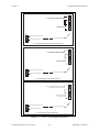
•
•
•
•
•
•
•
•
•
•
•
•
•
•
•
W7
VME BTO
Chain Position
•
•
•
•
•
•
•
•
•
b. Non-Slot 0 VXI-MXI without BTO,
the VXI-MXI Closest to Slot 0,
Multiple VXI-MXIs in Mainframe
a. Slot 0 VXI-MXI without BTO,
Multiple VXI-MXIs in Mainframe
W7
VME BTO
Chain Position
•
W7
VME BTO
Chain Position
•
•
•
•
•
•
W7
d. Non-Slot 0 VXI-MXI without BTO,
the VXI-MXI Furthermost from Slot 0,
Multiple VXI-MXIs in Mainframe
Figure 3-10. No VMEbus Timeout; Multiple VXI-MXIs in Mainframe
VXI-MXI User Manual
3-12
© National Instruments Corporation
Chapter 3
Configuration and Installation
Interlocked Arbitration Mode
Interlocked arbitration mode is an optional mode of operation in which the system performs as
one large VXIbus mainframe with only one master of the entire system (VXIbus and MXIbus) at
any given moment. This mode of operation prevents deadlocks by interlocking all arbitration in
the VXIbus/MXIbus system. Refer to Chapter 6 for a thorough discussion of interlocked
arbitration mode.
In the normal operating mode, there can be multiple masters operating simultaneously in the
VXIbus/MXIbus system. A deadlock occurs when a MXIbus master requests use of a VXIbus
resource in another VXIbus mainframe while a VXIbus master in that mainframe is in the
process of requesting a resource across the MXIbus. When this situation occurs, the VXIbus
master must give up its bus ownership to resolve the conflict. The BERR signal is used to
terminate the transfer on the VMEbus; however, devices in the VXIbus mainframe must be able
to detect a BERR caused by a deadlock condition so that they can retry the operation.
The VXI-MXI is shipped from the factory configured for normal operating mode. If MXIbus
transfers will be occurring both into and out of the mainframe and the VXIbus modules in your
system do not have the capability for handling BERR exceptions caused by deadlock conditions,
you may want to configure the VXI-MXI for interlocked arbitration mode. In this mode, no
changes will need to be made to software. However, parallel processing in separate VXIbus
mainframes is no longer possible, and system performance may be lower than in normal
operating mode.
VMEbus requesters are awarded the bus when they receive an active signal on the daisy-chained
bus grant line. Requesters closest to the Slot 0 device have higher priority, therefore, than
devices installed in slots farther from Slot 0. In addition, four bus request levels further prioritize
modules. For proper operation in interlocked arbitration mode, all VXI-MXIs should be
configured to request at bus request level 3, the factory default setting. In addition, only one
mainframe can have a requester at a higher priority than the VXI-MXIs in that mainframe. This
requester may be a Slot 0 device other than a VXI-MXI, such as a multiframe Resource
Manager. In all the other mainframes, the VXI-MXIs must be the highest priority requesters.
This means that a VXI-MXI should be installed in Slot 0 of its respective mainframe. In the case
of multiple VXI-MXIs in a single mainframe, the additional VXI-MXIs should be installed in the
slots adjacent to the Slot 0 VXI-MXI.
Note:
Interlocked arbitration mode has a potential for long access times. Therefore, you
should configure bus timeouts for adequate times.
In a VXIbus/MXIbus system, you can configure some VXI-MXIs for normal operating mode and
others for interlocked arbitration mode. The VXIbus mainframes configured in interlocked
arbitration mode will be interlocked with each other and the mainframes configured for normal
operating mode can perform transfers in parallel. This type of system configuration is
recommended if you have one of the following situations:
•
A VXIbus mainframe with only slave devices and no masters. Without bus masters, there is
no chance for deadlock. The VXI-MXIs in this mainframe can be configured for normal
operating mode.
•
A VXIbus mainframe with both masters and slaves, but the masters communicate only with
the slaves in their mainframe. The masters never attempt transfers across the MXIbus so
there is no chance for deadlock when a MXIbus master attempts a transfer into the VXI
mainframe. The VXI-MXIs in this mainframe can be configured for normal operating mode.
© National Instruments Corporation
3-13
VXI-MXI User Manual
Configuration and Installation
Chapter 3
Select interlocked arbitration mode by changing the default setting of the slide switch from
Normal to Interlocked Bus Cycles as shown in Figure 3-11.
Interlocked Bus Cycles
Interlocked Bus Cycles
S3
S3
Normal
Normal
a. Normal Operating Mode (Default Setting)
b. Interlocked Bus Cycle Mode
Figure 3-11. Interlocked Arbitration Mode Selection
MXIbus System Controller
The MXIbus System Controller slide switch selects whether or not the VXI-MXI interface
module is the MXIbus System Controller. The MXIbus System Controller is the first device in
the MXIbus daisy-chain. The System Controller supplies the arbitration circuitry for MXIbus
arbitration, the MXIbus interrupt acknowledge daisy-chain driver, and the MXIbus bus timeout
unit. The VXI-MXI is shipped from the factory configured for non-MXIbus System Controller
operation. If the VXI-MXI is the first device in the MXIbus link, configure the VXI-MXI as the
MXIbus System Controller by changing the default setting of the slide switch from Disabled to
Enabled, as shown in Figure 3-12.
VXI-MXI User Manual
3-14
© National Instruments Corporation
Chapter 3
Configuration and Installation
MXIbus System Controller Enabled
S4
Disabled
a. Not MXIbus System Controller
(Default Setting)
MXIbus System Controller Enabled
S4
Disabled
b. MXIbus System Controller
Figure 3-12. MXIbus System Controller Selection
© National Instruments Corporation
3-15
VXI-MXI User Manual
Configuration and Installation
Chapter 3
MXIbus System Controller Timeout
The MXIbus System Controller is also responsible for the MXIbus system timeout. The timeout
period begins when a MXIbus data strobe (DS) is received. The period stops when a MXIbus
DTACK or BERR is detected. If a timeout occurs, the MXIbus System Controller sends a
MXIbus BERR to clear the MXIbus system. On power up, this timeout is between 100 µs and
400 µs as configured by the MXI Controller BTO Level jumper array (refer to Figure 3-1 for its
location). You can extend the timeout to a value between 100 ms and 400 ms by setting the
LNGMXSCTO bit in the MXIbus Control Register. It is best to have a long MXIbus System
Controller timeout in MXIbus systems with many devices or in situations where one or more
MXIbus devices use a large amount of MXIbus bandwidth.
Figure 3-13 shows how to position the jumper array to set the MXIbus System Controller
timeout value. When the VXI-MXI is not configured to be the MXIbus System Controller, the
setting of this jumper array has no effect. Notice that when the LNGMXSCTO bit in the
MXIbus Control Register is zero, the selected timeout value is in microseconds. When the
LNGMXSCTO bit is one, the selected timeout value is in milliseconds.
MXI Controller BTO Level
MXI Controller BTO Level
•
•
•
•
•
c. 400 µs/ms MXIbus
System Controller Timeout
•
100 µ/ms
•
200 µ/ms
•
•
•
W8
•
DISABLE
MXI Controller BTO Level
•
•
•
•
400 µ/ms
•
•
•
•
•
200 µ/ms
DISABLE
b. 200 µs/ms MXIbus
System Controller Timeout
MXI Controller BTO Level
100 µ/ms
400 µ/ms
400 µ/ms
•
•
a. 100 µs/ms MXIbus
System Controller Timeout
(Default Setting)
W8
200 µ/ms
•
•
•
DISABLE
100 µ/ms
•
•
400 µ/ms
W8
•
•
•
200 µ/ms
•
100 µ/ms
•
W8
DISABLE
d. Disable MXIbus System
Controller Timeout
Figure 3-13. MXIbus System Controller Timeout Value Selection
VXI-MXI User Manual
3-16
© National Instruments Corporation
Chapter 3
Configuration and Installation
MXIbus Fairness Option
The MXIbus fairness feature ensures that all requesting devices will be granted use of the
MXIbus. This feature prevents a high priority MXIbus device from consuming all of the
MXIbus bandwidth. If MXIbus fairness is enabled, a MXIbus master will not request the bus
until it detects that no other devices are requesting the bus. MXIbus fairness ensures that all
MXIbus masters have an equal opportunity to use the MXIbus.
The VXI-MXI factory default setting has the MXIbus fairness feature disabled. Keep this option
disabled if a device in your mainframe needs a large portion of the MXIbus bandwidth without
interruptions from lower priority requesters. In an unfair system, the order in which you connect
the MXIbus devices in the daisy-chain determines the priority of each device's MXIbus request.
MXIbus requesters closer to the MXIbus System Controller have higher priority than those
further down the MXIbus chain. The MXIbus fairness feature is controlled by the Fairness slide
switch. If you want your VXI-MXI to be a fair requester, change the slide switch from the
Disabled setting to Enabled, as shown in Figure 3-14.
Fairness Enabled
Fairness Enabled
S2
S2
Disabled
Disabled
a. Fairness Disabled
(Default Setting)
b. Fairness Enabled
Figure 3-14. MXIbus Fair Requester Selection
© National Instruments Corporation
3-17
VXI-MXI User Manual
Configuration and Installation
Chapter 3
CLK10 Source
The VXIbus specification requires that Slot 0 devices supply a clock signal, CLK10, on a
differential ECL output. The VXI-MXI can generate the CLK10 signal from an onboard
oscillator (10 MHz with a 50% ±5% duty cycle), route an external clock signal from the front
panel SMB connector labeled EXT CLK to the CLK10 signal, or receive the CLK10 signal. Use
the CLK10 Source Select jumper array to select one of these options, as shown in Figure 3-15.
The VXI-MXI is configured at the factory to be a Slot 0 device driving the CLK10 signal from
the onboard oscillator. If you are installing the VXI-MXI in a slot other than Slot 0, change the
jumper array so that the VXI-MXI is configured to receive the CLK10 signal.
If your VXI-MXI includes the INTX daughter card option, the VXI-MXI has the ability to route
the CLK10 signal from the INTX connector. If you intend to do this, remove the jumper
completely and store it in a safe place in case you need to change your system configuration at a
later date.
Warning:
Configuring more than one VXIbus device to drive the CLK10 lines can
damage the VXIbus backplane, the CLK10 drivers on the VXIbus devices, or
both.
VXI-MXI User Manual
3-18
© National Instruments Corporation
Chapter 3
Configuration and Installation
•
•
•
•
•
•
•
•
•
W9
W10
•
Receive CLK10, Non-Slot 0
•
•
Drive CLK10 from SMB CLK10, Slot 0
•
•
Drive CLK10 from onboard 10MHz, Slot 0
•
CLK10 Source
Select
a. Onboard 10 MHz
VXI-MXI Installed in Slot 0
(Default Setting)
•
•
•
•
•
•
•
W9
W10
•
Receive CLK10, Non-Slot 0
•
•
Drive CLK10 from SMB CLK10, Slot 0
•
Drive CLK10 from onboard 10MHz, Slot 0
•
CLK10 Source
Select
b. External Clock
VXI-MXI Installed in Slot 0
•
•
•
•
•
•
•
•
W10
W9
•
Receive CLK10, Non-Slot 0
•
Drive CLK10 from SMB CLK10, Slot 0
•
Drive CLK10 from onboard 10MHz, Slot 0
•
CLK10 Source
Select
c. Do Not Source CLK10;
VXI-MXI Not Installed in Slot 0
•
•
•
•
•
•
Receive CLK10, Non-Slot 0
•
Drive CLK10 from SMB CLK10, Slot 0
•
Drive CLK10 from onboard 10MHz, Slot 0
•
CLK10 Source
Select
W10
W9
d. Source CLK10 from INTX
VXI-MXI Installed in Slot 0
Figure 3-15. CLK10 Source Signal Options
© National Instruments Corporation
3-19
VXI-MXI User Manual
Configuration and Installation
Chapter 3
EXT CLK SMB Input/Output
If you want to have synchronized CLK10 signals in multiple VXIbus mainframes, you can
connect the CLK10 signals of the two mainframes together using the EXT CLK SMB connectors
on the front panel of the VXI-MXI. One mainframe should source the CLK10 signal to the SMB
connection. The other device receives the CLK10 signal from the SMB connection and drives it
on the VXIbus CLK10 lines. This device must be installed in Slot 0 so that it can drive the
VXIbus CLK10 signal. For this option, set the CLK10 Source Select jumpers to select an
external clock as shown in Figure 3-15(b).
Slide switch S6 sets whether the EXT CLK SMB is used as an input to receive a CLK10 signal
to drive on the VXIbus, or as an output to source the CLK10 signal to another VXIbus
mainframe. Figure 3-16 shows the two settings of slide switch S6.
S6
CLK10 in from SMB
CLK10 out SMB
a. Drive EXT CLK
(Default Setting)
S6
CLK10 in from SMB
CLK10 out SMB
b. Receive EXT CLK
Figure 3-16. EXT CLK SMB Input/Output Setting
INTX CLK10 Mapping
If your VXI-MXI includes the INTX daughter card option, you can use the INTX CLK10 Routing
switches to route the CLK10 signal to or from the INTX connector. The INTX daughter card is
shipped from the factory with the CLK10 mapping function disabled. Refer to Figure 3-2 to
view the location of the three slide switches used to configure the INTX CLK10 mapping.
Figure 3-17 shows how to set these switches to (a) disable CLK10 mapping, (b) enable CLK10
to map out of the mainframe through the INTX connector, or (c) enable CLK10 into the
mainframe from the INTX connector.
VXI-MXI User Manual
3-20
© National Instruments Corporation
Chapter 3
Configuration and Installation
W2
Drive CLK10 from INTX CLK10, Slot 0
(W9 and W10 must be removed)
Do Not Drive CLK10
from INTX CLK10
W3
W1
Receive CLK10 from INTX
INTX CLK10 Routing
Drive CLK10 out INTX
a. CLK10 Mapping Disabled (Default Setting)
W2
Drive CLK10 from INTX CLK10, Slot 0
(W9 and W10 must be removed)
Do Not Drive CLK10
from INTX CLK10
W3
W1
Receive CLK10 from INTX
INTX CLK10 Routing
Drive CLK10 out INTX
b. CLK10 Mapped out of a Mainframe
W2
Drive CLK10 from INTX CLK10, Slot 0
(W9 and W10 must be removed)
Do Not Drive CLK10
from INTX CLK10
W3
W1
Receive CLK10 from INTX
INTX CLK10 Routing
Drive CLK10 out INTX
c. CLK10 Mapped into Mainframe
Figure 3-17. INTX CLK10 Mapping Switches
© National Instruments Corporation
3-21
VXI-MXI User Manual
Configuration and Installation
Chapter 3
The VXI-MXI must be installed in Slot 0 if you want to route the INTX CLK10 signal to the
VXIbus CLK10 signal. The CLK10 Source Select jumpers on the VXI-MXI must be set to
configure the VXI-MXI to receive the CLK10 because the INTX daughter card will now be
sourcing the clock signal. You can configure the VXI-MXI to be installed in any slot when the
INTX CLK10 Routing switches are enabled to map the VXIbus CLK10 signal to the INTX
connector.
Warning:
Configuring more than one VXIbus device to drive the CLK10 lines or
configuring both the VXI-MXI and the INTX daughter card to drive CLK10
can damage the VXIbus backplane, the CLK10 drivers on the VXIbus devices,
or both.
Trigger Input Termination
The Trigger Input SMB connector can be terminated to 50 ohms by changing the position of
slide switch S5. See Figure 3-18.
None
50Ω Termination
S5
a. Trigger Input SMB not Terminated
to 50Ω (Default Setting)
None
50Ω Termination
S5
a. Trigger Input SMB Terminated to 50Ω
Figure 3-18. Trigger Input Termination Option Settings
VXI-MXI User Manual
3-22
© National Instruments Corporation
Chapter 3
Configuration and Installation
Reset Signal Select
The VXI-MXI generates a 200 ms active low pulse both on power-up and when you press the
pushbutton system reset switch on the front panel. Using the Reset Signal Select slide switch,
you can route the pulse to either VMEbus signal ACFAIL* or SYSRESET*. See Figure 3-19.
Reset Signal Select
Reset Signal Select
S7
S7
ACFAIL*
ACFAIL*
SYSRESET*
SYSRESET*
a. SYSRESET* Asserted (Default Setting)
b. ACFAIL* Asserted
Figure 3-19. Reset Signal Selection Settings
Installing the VXI-MXI Hardware
The VXI-MXI is a VXIbus extender device; it has no onboard intelligence or memory. For the
VXI-MXI to perform as a MXIbus master, a device with VMEbus master capability must be
installed in the VXIbus mainframe. For the VXI-MXI to perform as a MXIbus slave in A16,
A24, or A32 space, a slave VMEbus device with resources in those address spaces must be
installed in the VXIbus mainframe.
Warning:
The VXI-MXI is shipped from the factory configured to be installed into Slot 0
of your VXIbus mainframe. Installing your VXI-MXI into any slot other than
Slot 0 without changing its default configuration can damage the VXI-MXI, the
VXIbus backplane, or both.
If a device is already installed in Slot 0, reconfigure that device and install it in another slot, or
reconfigure your VXI-MXI for Non-Slot 0 use. Do not install a device configured for Slot 0 into
another slot without first reconfiguring it for Non-Slot 0 use. Remember that the VXI-MXI must
have the VMEbus BTO. If another device is providing the VMEbus BTO function, disable its
BTO before installing the VXI-MXI.
© National Instruments Corporation
3-23
VXI-MXI User Manual
Configuration and Installation
Chapter 3
MXIbus Termination
VXI-MXI
MXIbus Cable
VXI
Mainframe
VXI-MXI
PC/AT
VXI
Mainframe
VXI-MXI
The MXIbus is a matched impedance bus and requires termination networks at the first and last
device in the MXIbus daisy-chain. These terminations minimize reflections caused by
impedance discontinuities at the ends of the cables. These termination networks are located at
the end device's MXIbus connectors and can be either external self-contained modules or internal
plug-in resistor packages. The VXI-MXI comes with terminating resistors installed. If you
prefer, you can replace them with external resistor packages for easy system reconfiguration.
Figure 3-20 shows an example of a daisy-chained MXIbus system, including terminators.
VXI
Mainframe
MXIbus System
Controller
Upstream
Terminator
VXI
Mainframe
VXI-MXI
62-pin MXIbus Connectors
Downstream
Terminator
Figure 3-20. MXIbus System
The VXI-MXI uses the TERMPWR connection on the MXIbus connector as the power source
for external MXIbus termination networks. TERMPWR is protected by a fuse that limits the
maximum current that can be drawn to 2A. The fuse is soldered on the module and is not user
replaceable.
Note:
TERMPWR is not intended to provide power to any other device.
The VXI-MXI is shipped from the factory with terminating SIP resistor networks installed. If
the VXI-MXI will be the first or last device in the MXIbus daisy-chain and external terminating
VXI-MXI User Manual
3-24
© National Instruments Corporation
Configuration and Installation
Chapter 3
If the daughter card will be the first or last device in the INTX chain (irrespective of the
VXI-MXI's position in the MXIbus chain), you should leave these terminators in place. If the
daughter card is not going to be an end device, remove all four terminating resistor networks
from their sockets. Store them in a safe place in case your system configuration changes. Figure
3-22 shows an example of a daisy-chained MXIbus and INTX system, including terminators.
PC/AT
VXI-MXI
Upstream
MXIbus
Terminator
VXI
Mainframe
MXIbus System
Controller
INTX Terminators
VXI-MXI
VXI
Mainframe
VXI
Mainframe
VXI-MXI
62-pin MXIbus Connectors
VXI-MXI
MXIbus Cable
VXI
Mainframe
44-pin INTX
Connectors
Downstream
MXIbus
Terminator
INTX Terminators
Figure 3-22. INTX Terminator Example
Installation Instructions
Verify the following configuration considerations before installing the VXI-MXI:
•
If installing the VXI-MXI in a slot other than Slot 0, verify that you have changed the
settings of the two VXIbus Slot 0 slide switches, the VME BTO Chain Position jumper, and
the CLK10 Source Select jumpers.
•
Multiple VXI-MXIs must be installed in adjacent slots with proper VME BTO Chain Position
jumper settings, and the VMEbus BTO must be enabled on one of them.
VXI-MXI User Manual
3-26
© National Instruments Corporation
Chapter 3
Configuration and Installation
•
If interlocked mode is used, the VXI-MXIs must be the highest priority VMEbus requesters
in their mainframe. However, one, and only one, mainframe in the MXIbus link can have a
higher priority VMEbus requester than its VXI-MXIs.
•
The first and last MXIbus devices in the MXIbus link must be terminated.
•
No two devices in your VXIbus/MXIbus system can have the same logical address.
After you verify the termination networks, switches, and jumpers, record all settings on the
VXI-MXI Hardware and Software Configuration Form in Appendix F, Customer
Communication. You are now ready to install the VXI-MXI. Following are general instructions
for installing your VXI-MXI in your VXIbus mainframe. Consult the user manual or technical
reference manual of your VXIbus mainframe for specific instructions and warnings.
1. Remove power from the mainframe.
2. Remove or open any doors or covers blocking access to the mainframe slots.
3. If the VXI-MXI will be installed in a D-size mainframe, install a support designed for
installing C-size cards in D-size mainframes.
4. Insert the VXI-MXI into the slot of the mainframe by aligning the top and bottom of the card
with the card guides inside the mainframe. Slowly push the VXI-MXI straight into the slot
until it seats in the backplane receptacles. The front panel of the VXI-MXI should be even
with the front panel of the mainframe.
5. Tighten the retaining screws on the top and bottom edges of the front panel.
6. Check installation.
7. Connect MXIbus and SMB cables as required.
8. Replace or close any doors or covers to the mainframe.
9. Restore power to the mainframe.
Connecting the INTX Cable
For VXI-MXIs with the INTX daughter card option, you must use special INTX cables for
routing the additional VMEbus and VXIbus signals to other frames. The INTX cable provides
either a straight point to point link (National Instruments part number 180980-XX where XX is
the length in meters) or a single connector to dual connector link (National Instruments part
number 180982-XX, where XX is the length in meters), which gives you the ability to connect
more than two devices together.
Notice that while the MXIbus is a prioritized daisy-chain, INTX signals are bused to every
device and no priority exists. Like the MXIbus, however, INTX cables must be connected in a
daisy-chain fashion to prevent impedance discontinuities from stubs that are created in a startype configuration.
Secure the INTX cable(s) on the back of the INTX connector using the captive screw elements to
ensure that the cable(s) will not accidentally become disconnected.
© National Instruments Corporation
3-27
VXI-MXI User Manual
Configuration and Installation
Chapter 3
In a properly configured MXIbus system, the first and last devices in the daisy-chain each have
only one cable connected to their device connector. MXIbus devices that are neither the first nor
the last device in the daisy-chain have two (and only two) MXIbus cables attached to their device
connector.
System Power Cycling Requirements
A distributed architecture such as MXIbus does not have a common power bus or reset signal to
ensure that all devices within the extended system are initialized at the same time. Therefore,
powering-on a device after other devices in the system have already received power and become
functional may cause unintended bus activity due to the power-up state of that device. This bus
activity could result in a powered, functional MXIbus device making an attempt to respond. If
this response initiates bus arbitration, for example, the arbitration mechanism could become hung
while waiting for a nonexistent master to assume control of the bus.
To guard against this type of bus activity, you should keep in mind that two types of systems
exist with respect to power cycling. The first of these is one in which power is supplied to all
devices at roughly the same time as is the case for a system with a master power switch. In such
a system, proper operation is guaranteed if the last device to reach 5V does so within roughly
half of a second of the first device to reach 5V. The second type of system is one in which power
is applied to each MXIbus device separately. In this type of system, you must power-on devices
starting with the device at the end of the MXIbus link opposite the MXIbus System Controller
and progress towards the MXIbus System Controller. The MXIbus System Controller should be
the last device on the MXIbus link to receive power. Conversely, when removing system power,
you should power-down the device farthest from the MXIbus System Controller last so that the
termination resistors on the end device ensure that the MXIbus lines remain unasserted
throughout the power-down sequence.
When shutting down a system, you must ensure that all devices that could be adversely affected
by unintended bus cycles or interrupts have their windows and interrupt mapping disabled. The
VXI-MXI itself will not be affected during power-down; however, there may be devices in the
same frame as the VXI-MXI that could be affected.
Table 3-1 summarizes MXIbus system power cycling requirements.
Table 3-1. MXIbus System Power Cycling Requirements
System Type
Power-On Requirements
Power-Off Requirements
Master Power
Switch
All devices must receive power
within 0.5 seconds of each other.
Disable all A24 and A32 inward
mapping to devices that could be
adversely affected by an
unintended access. Disable all
mapping of interrupts.
Distributed
Power-on devices along the
MXIbus link beginning with the
non-MXIbus System Controller
end of the MXIbus link. Make
sure the MXIbus System
Controller is the last to receive
power.
Power-off devices in opposite
order of power-on sequence
(power off MXIbus System
Controller first). Disable all A24
and A32 inward mapping to
devices that could be adversely
affected by an unintended access.
Disable all mapping of interrupts.
VXI-MXI User Manual
3-30
© National Instruments Corporation
Chapter 3
Configuration and Installation
Keep in mind that a system can contain only one device acting as the VXIbus Resource Manager
(RM). It is important that the RM be run only after all other devices in the system have been
powered on. Because many RMs execute automatically upon power-up, you must be sure when
working with a distributed system to power-on the device containing the RM last. This implies
that any VXI-MXIs in that frame must be the MXIbus System Controllers for their respective
MXIbus systems to keep the preceding power-on procedures for individual MXIbus systems.
VMEbus Devices in VXIbus/MXIbus Systems
If you have VMEbus devices installed in your VXIbus system, pay special attention to how the
A16 resources used by the VMEbus cards are configured. The VXIbus specification has
reserved the upper 16 KB of A16 space for configuration registers on VXIbus devices. During
system initialization, the system Resource Manager scans the upper 16 KB of A16 searching for
VXIbus devices. Ensure that VMEbus devices are not mistaken for VXIbus devices.
If possible, you should configure the A16 resources for your VMEbus boards in the lower 48 KB
(0000 through BFFF hex) of A16 space, so as to not interfere with VXIbus configuration space.
The logical address window is then used for mapping configuration space for VXIbus devices,
while the A16 window is used for mapping configuration space for VMEbus devices. If you
must configure any of the VMEbus module's A16 resources in the upper 16 KB (C000 through
FFFF hex) of A16 space, you need to indicate to the system Resource Manager that there are
non-VXIbus foreign devices installed. Be careful not to configure any static VXIbus logical
addresses in the portions of A16 space occupied by the VMEbus devices.
© National Instruments Corporation
3-31
VXI-MXI User Manual
Chapter 4
Register Descriptions
This chapter contains detailed information on the use of the VXI-MXI registers, which are used
to configure and control the module's operation. All of these configuration registers are
accessible from the VMEbus (in the VXIbus configuration space) and from the MXIbus. If you
are not writing your own multiframe Resource Manager routines, you can skip over this chapter.
Register Maps
The register map for the VXI-MXI configuration registers is shown in Table 4-1 and Figure 4-1.
The table gives the register name, the register address, the size of the register in bits, and the type
of the register (read only, write only, or read/write). The base address for the VXI-MXI
configuration space in A16 space is equal to the VXIbus logical address assigned to the
VXI-MXI shifted left six times and ORed with hex C000.
Register Sizes
The VMEbus supports three different transfer sizes for read/write operations: 8-bit, 16-bit, or
32-bit. Table 4-1 shows the size of the registers on the VXI-MXI. All 16-bit registers can be
accessed using 8-bit read/write operations.
Register Description Format
Each register bit map shows a diagram of the register with the most significant bit (bit 15 for a
16-bit register, bit 7 for an 8-bit register) shown on the left, and the least significant bit (bit 0)
shown on the right. A square is used to represent each bit. Each bit is labeled with a name inside
its square. An asterisk (*) after the bit name indicates that the signal is active low. An asterisk is
equivalent to an overbar.
Hard and Soft Reset
Each register description indicates whether the bits are cleared by a hard and/or soft reset. A
hard reset occurs when the mainframe is powered on and when the VMEbus SYSRESET signal
is active. A hard reset clears all the registers on the VXI-MXI. A soft reset occurs when the
RESET bit in the VXIbus Control Register is set. A soft reset clears signals that are asserted by
bits in the configuration registers but does not clear configuration information stored in the
configuration registers.
© National Instruments Corporation
4-1
VXI-MXI User Manual
Register Descriptions
Chapter 4
Table 4-1. VXI-MXI Register Map
Register Name
Offset from Base
Address (Hex)
Type
Size
0
2
4
8
A
C
E
10
12
14
18
1E
20
22
24
26
28
2A
2C
2E
34
36
32
34
36
38
3A
3C
3E
Read Only
Read Only
Read/Write
Read/Write
Read/Write
Read/Write
Read/Write
Read/Write
Read/Write
Read/Write
Read/Write
Read Only
Read/Write
Read/Write
Read/Write
Read/Write
Read/Write
Read/Write
Read/Write
Read/Write
Write Only
Write Only
Read Only
Read Only
Read Only
Read Only
Read Only
Read Only
Read Only
16-bit
16-bit
16-bit
16-bit
16-bit
16-bit
16-bit
16-bit
16-bit
16-bit
16-bit
16-bit
16-bit
16-bit
16-bit
16-bit
16-bit
16-bit
16-bit
16-bit
8-bit
8-bit
16-bit
16-bit
16-bit
16-bit
16-bit
16-bit
16-bit
VXIbus ID Register
Device Type Register
VXIbus Status/Control Register
MODID Register
Logical Address Window Register
A16 Window Map Register
A24 Window Map Register
A32 Window Map Register
INTX Interrupt Configuration *
INTX Trigger Configuration *
INTX Utility Configuration *
Subclass Register
MXIbus Status/Control Register
MXIbus Lock Register
MXIbus IRQ Configuration Register
Drive Triggers/Read LA Register
Trigger Mode Selection Register
Interrupt Status/Control Register
Status/ID Register
MXIbus Trigger Configuration Register
Trigger Sync. Acknowledge Register
Trigger Async. Acknowledge Register
Interrupt Acknowledge for IRQ1
Interrupt Acknowledge for IRQ2
Interrupt Acknowledge for IRQ3
Interrupt Acknowledge for IRQ4
Interrupt Acknowledge for IRQ5
Interrupt Acknowledge for IRQ6
Interrupt Acknowledge for IRQ7
*
The three INTX registers at offsets 12, 14, and 18 are only available on VXI-MXIs with the
INTX daughter card option. On VXI-MXIs without the INTX option, the entire range
between offsets 12 and 1C (inclusive) is VXI-MXI Reserved Space.
VXI-MXI User Manual
4-2
© National Instruments Corporation
Chapter 4
Register Descriptions
Offset from Base
Logical Address
3E
Interrupt Acknowledge 7
3C
Interrupt Acknowledge 6
3A
38
Interrupt Acknowledge 5
Interrupt Acknowledge 4
36 Interrupt Ack 3 / Trig Async Ack
34 Interrupt Ack 2 / Trig Sync Ack
32
Interrupt Acknowledge 1
VXI-MXI
Defined
Registers
30
2E
VXI-MXI Reserved
MXIbus Trigger Configuration
2C
Status / ID
2A
28
Interrupt Status / Control
Trigger Mode Register
26
Drive Triggers / Read LA
24
22
MXIbus IRQ Configuration
MXIbus Lock Register
20
MXIbus Status / Control
1E
1C
Subclass Register
VXI-MXI Reserved
1A
VXIbus
Extender
Registers
18
16
INTX Utility Configuration
VXI-MXI Reserved
14
INTX Trigger Configuration
INTX Interrupt Configuration
12
10
Basic VXI
Configuration
Registers
A32 Window Map Register
0E
A24 Window Map Register
0C
0A
A16 Window Map Register
Logical Address Window
08
06
MODID Register
Reserved
04
VXIbus Status / Control
02
00
Device Type
VXIbus ID Register
16-bit Words
Figure 4-1. VXI-MXI Register Map
© National Instruments Corporation
4-3
VXI-MXI User Manual
Register Descriptions
Chapter 4
VXIbus Configuration Registers
These registers are defined by the VXIbus specification for all VXIbus devices.
VXIbus ID Register
VXIbus Address:
Base Address + 0 (hex)
Attributes:
Read Only
15
14
13
0
1
DEVCLASS
12
1
1
ADDR
11
10
9
8
1
1
1
1
7
6
5
4
3
2
1
1
1
MANID
1
1
0
1
1
0 R
0
This register provides information about this device and its configuration. The bits in this
register are configured in hardware as shown above. Hard and soft resets have no effect on this
register.
Bit
Mnemonic
Description
15-14r
DEVCLASS
Device Class Bits
These bits indicate the device class of the VXIbus device as
follows:
00 = Memory
01 = Extended
10 = Message-Based
11 = Register-Based
The VXI-MXI is an extended device defined by National
Instruments; therefore, these bits are configured in hardware as
binary 01.
13-12r
ADDR
Address Space Bits
These bits indicate the address spaces in which the VXIbus device
has operational registers as follows:
00 = A16/A24
01 = A16/A32
10 = Reserved
11 = A16 Only
The VXI-MXI has operational registers in A16 only; therefore,
these bits are configured in hardware as binary 11.
VXI-MXI User Manual
4-4
© National Instruments Corporation
Chapter 4
11-0r
Register Descriptions
MANID
Manufacturer ID Bits
This number uniquely identifies the manufacturer of the VXIbus
device. These bits are configured in hardware as hex FF6, the
VXIbus manufacturer ID number assigned to National Instruments.
© National Instruments Corporation
4-5
VXI-MXI User Manual
Register Descriptions
Chapter 4
Device Type Register
VXIbus Address:
Base Address + 2 (hex)
Attributes:
Read Only
15
14
13
12
11
10
9
8
7
6
5
4
3
2
1
0
0
0
0
1/0
0
0
0
1
MODEL
1
1
1
1
1
1
0 R
0
This register indicates how much VMEbus memory is required by this VXIbus device, and
identifies this device with a manufacturer's unique model code. The bits in this register are set in
hardware to the values shown above. Hard and soft resets have no effect on this register.
Bit
Mnemonic
Description
15-0r
MODEL
Model Code Bits
These bits contain a unique number assigned to this device by the
manufacturer to identify this device. Model codes between 0-FF
are assigned to Slot 0 devices. When the VXI-MXI is in Slot 0, bit
11 is 0 and its model code is hex 00FE. When the VXI-MXI is not
in Slot 0, bit 11 is 1 and its model code is hex 08FE.
VXI-MXI User Manual
4-6
© National Instruments Corporation
Chapter 4
Register Descriptions
VXIbus Status/Control Register
VXIbus Address:
Base Address + 4 (hex)
Attributes:
Read/Write
15
1
0
14
MODID*
0
13
12
11
10
0
0
0
0
7
6
5
4
0
0
3
RDY
0
2
PASS
0
EDTYPE
VERSION
0
0
9
1
0
1
1
0
8
R
ACCDIR
0
W
0
R
RESET
RESET
W
This register provides status information about this VXIbus device and provides a bit to force the
VXI-MXI into a Soft Reset state. The RESET bit is cleared on a hard reset. Hard and soft resets
have no effect on the other bits on this register.
Bit
Mnemonic
Description
15r/w,
1
14-10w,
9r/w, 8w,
7-2w, 1r/w
Reserved Bits
14r
MODID Line Status Bit
MODID*
These bits are reserved and read back as ones. Write a zero when
writing to these bits.
This bit is zero when the device is selected by the MODID line,
and one when the device is not selected by the MODID line. This
bit is read only.
13-10r
EDTYPE
Extended Device Type Class Bits
These bits are driven low by an optional daughter card installed on
the two 96-pin daughter card connectors. They identify the
daughter card and its capabilities. When a daughter card is not
installed, these bits are all ones. The INTX daughter card has been
assigned extended device type class hex E; therefore, when the
VXI-MXI includes this option, these bits are hex E. These bits are
read only.
8r
ACCDIR
Access Direction Bit
When this bit is one, the current access to the Status register
originated from a device on the MXIbus. When this bit is zero, the
current access to the Status register originated from a device on the
VMEbus. This bit is read only.
© National Instruments Corporation
4-7
VXI-MXI User Manual
Register Descriptions
7-4r
VERSION
Chapter 4
VXI-MXI Version Number Bits
These bits specify the revision version number of the VXI-MXI
according the table below. These bits are read only.
Version Number
Hex D
Hex C
Hex B
Hex A
3r
RDY
VXI-MXI Revision
Revision D
Revision E
Revision F
Revision G
Ready Bit
This bit is set to one in hardware to indicate that the device is ready
to execute its full functionality. This bit is read only.
2r
PASS
Passed Bit
This bit is set to one in hardware to indicate that the device is
functional. This bit is read only.
0r/w
RESET
Reset Bit
When this bit is set, the VXI-MXI is forced into the Soft Reset
state. When this bit is cleared, the VXI-MXI is in the normal
operation state. This bit is readable and is cleared on a hard reset.
VXI-MXI User Manual
4-8
© National Instruments Corporation
Chapter 4
Register Descriptions
VXIbus Extender Registers
These registers are defined for VXIbus extender devices.
MODID Register
VXIbus Address:
Base Address + 8 (hex)
Attributes:
Read/Write
15
14
13
12
11
10
9
8
0
0
OUTEN
MODID12
MODID11
MODID10
MODID9
MODID8
7
6
5
4
3
2
1
0
MODID7
MODID6
MODID5
MODID4
MODID3
MODID2
MODID1
MODID0
R/W
R/W
This register provides control and status of the MODID lines when the VXI-MXI is installed in
Slot 0.
Bit
Mnemonic
15-14r/w 0
Description
Reserved Bits
These bits are reserved and read back as zeros. Write a zero when
writing to these bits.
13r/w
OUTEN
MODID Output Enable Bits
When this bit is set, the VXI-MXI is enabled to drive the MODID
lines. When this bit is cleared, the MODID drivers are disabled.
This bit should only be set when the VXI-MXI is in Slot 0. This
bit is cleared on both hard and soft resets.
12-0r/w
MODID[12-0]
MODID Drive Bits
If the OUTEN bit is set, setting one of these bits drives the
corresponding MODID line high, and clearing the bit drives the
line low. Independent of OUTEN, reading these bits always
returns the current status of the corresponding MODID lines. Hard
and soft resets have no effect on these bits.
© National Instruments Corporation
4-9
VXI-MXI User Manual
Register Descriptions
Chapter 4
Logical Address Window Register
VXIbus Address:
Base Address + A (hex)
Attributes:
Read/Write
This register defines the range of logical addresses that are mapped into and out of the VXI-MXI
through the MXIbus. This register defines a configuration window in the upper 16 KB of A16
space. These bits are cleared on a hard reset.
The CMODE bit in the MXIbus Control Register selects the format of this register. If the
CMODE bit is 0 (default), a Base/Size window comparison is used to determine the range of
addresses in the window. If the CMODE bit is set, an upper and lower bound is used to
determine the range of addresses in the window.
The Logical Address Window Register has the following format when the CMODE bit is
cleared:
15
0
0
14
LAEN
LAEN
13
LADIR
LADIR
12
1
0
11
1
0
10
LASIZE2
LASIZE2
7
6
5
4
3
2
LABASE7
LABASE6
LABASE5
LABASE4
Bit
Mnemonic
Description
15r/w
0
Reserved Bit
9
LASIZE1
LASIZE1
1
LABASE3 LABASE2 LABASE1
8
R
LASIZE0
LASIZE0
W
0
LABASE0
R/W
This bit is reserved and reads back as zero. Write a zero when
writing to these bits.
14r/w
LAEN
Logical Address Window Enable Bit
When this bit is set, the logical address mapping window is
enabled. When this bit is cleared, the logical address mapping
window is disabled except for the logical address of this device.
Access to the VXI-MXI's own configuration space is always
enabled.
13r/w
LADIR
Logical Address Window Direction Bit
When this bit is set, the logical address window applies to MXIbus
cycles that are mapped into VXIbus cycles (inward cycles). When
this bit is cleared, the logical address window applies to VXIbus
cycles that are mapped out into MXIbus cycles (outward cycles).
The complement of the defined range is mapped in the opposite
direction.
VXI-MXI User Manual
4-10
© National Instruments Corporation
Chapter 4
Register Descriptions
12-11r/w 1
LAEN
LADIR
Window Applies to
0
X
Disabled
1
0
VXI cycles to MXI cycles
1
MXI cycles to VXI cycles
Reserved Bits
These bits are reserved and read back as ones. Write a zero when
writing to these bits.
10-8r/w
LASIZE[2-0]
Logical Address Window Size Bits
This 3-bit number specifies the number of significant address bits
in the LABASE field that are compared when determining if an
address is in the logical address window. The number of logical
addresses in the window is 28-i where i is the value of LASIZE
[2-0]. Because i can range from 0 to 7, the minimum size of a
logical address window is 2, and the maximum size is 256.
7-0r/w
LABASE[7-0]
Logical Address Window Base Address Bits
These bits, in conjunction with the LASIZE bits, define the base
address of the Logical Address window for the VXI-MXI. The
LASIZE bits indicate the number of LABASE bits that are most
significant. LABASE7 is the most significant, and LABASE0 is
the least. The LABASE bits that are not significant can be
replaced with zeros to provide the base address of the logical
address window.
Logical Address Window Example:
LABASE
LASIZE
any value
00
08
18
3F
55
88
CC
AA
AA
AA
AA
AA
AA
AA
AA
0
1
2
3
4
5
6
7
0
1
2
3
4
5
6
7
© National Instruments Corporation
Logical Addresses in Window
00 to FF
00 to 7F
00 to 3F
00 to 1F
30 to 3F
50 to 57
88 to 8B
CC to CD
00 to FF
80 to FF
80 to BF
A0 to BF
A0 to AF
A8 to AF
A8 to AB
AA to AB
4-11
VXI-MXI User Manual
Register Descriptions
Chapter 4
The Logical Address Window Register has the following format when the CMODE bit is set:
15
14
13
12
11
10
9
LAHIGH7
LAHIGH6
LAHIGH5
LAHIGH4
7
6
5
4
3
2
1
0
LALOW7
LALOW6
LALOW5
LALOW4
LALOW3
LALOW2
LALOW1
LALOW0
LAHIGH3 LAHIGH2 LAHIGH1
Bit
Mnemonic
Description
15-8r/w
LAHIGH[7-0]
Logical Address Window Upper Bound Bits
8
LAHIGH0
R/W
R/W
These bits define the upper limit of the range of MXIbus logical
addresses that map into the VXIbus.
7-0r/w
LALOW[7-0]
Logical Address Window Lower Bound Bits
These bits define the lower limit of the range of MXIbus logical
addresses that map into the VXIbus.
This register defines the range of MXIbus logical addresses that map into the VXIbus where that
range is:
LAHIGH > range LALOW
The VXIbus logical addresses mapped out of the VXI-MXI are the inverse of this range, that is,
MXIbus logical addresses greater than or equal to the LAHIGH value or less than the LALOW
value.
To map a consecutive range of VXIbus logical addresses out of the VXI-MXI, the lower bound
of the range must be placed in the LAHIGH field and the upper bound in the LALOW field. In
this case, the range of VXIbus logical addresses mapped out of the VXI-MXI is:
LALOW > range LAHIGH
The MXIbus logical addresses mapped into the VXIbus are the inverse of this range, that is,
VXIbus logical addresses greater than or equal to the LALOW value or less than the LAHIGH
value.
The window is disabled whenever LAHIGH = LALOW = 0. All VXIbus logical addresses are
mapped out to the MXIbus when:
FF (hex) (LAHIGH = LALOW) 80 (hex)
All MXIbus logical addresses are mapped into the VXIbus when:
7F (hex) (LAHIGH = LALOW) > 0
VXI-MXI User Manual
4-12
© National Instruments Corporation
Chapter 4
Register Descriptions
To accommodate 8-bit devices that write to this register, the window is not enabled until the
lower byte of the register is written. Therefore, 8-bit devices should write the upper byte first,
then the lower byte.
© National Instruments Corporation
4-13
VXI-MXI User Manual
Register Descriptions
Chapter 4
A16 Window Map Register
VXIbus Address:
Base Address + C (hex)
Attributes:
Read/Write
This register defines the range of addresses in the lower 48 KB of A16 space that is mapped into
and out of the VXI-MXI through the MXIbus. Earlier versions of the VXI-MXI required the
A16 window to be statically configured with a DIP switch. Now the A16 window can only be
dynamically configured with this register. These bits are cleared on a hard reset.
The CMODE bit in the MXIbus Control Register selects the format of this register. If the
CMODE bit is 0 (default), a Base/Size window comparison is used to determine the range of
addresses in the window. If the CMODE bit is set, an upper and lower bound is used to
determine the range of addresses in the window.
The A16 Window Map Register has the following format when the CMODE bit is cleared:
15
0
0
14
A16EN
A16EN
13
A16DIR
A16DIR
12
1
0
11
1
0
10
A16SIZE2
A16SIZE2
7
6
5
4
3
2
9
8
R
A16SIZE1 A16SIZE0
A16SIZE1 A16SIZE0
W
1
0
A16BASE7 A16BASE6 A16BASE5 A16BASE4 A16BASE3 A16BASE2 A16BASE1 A16BASE0 R/W
Bit
Mnemonic
Description
15r/w
0
Reserved Bit
This bit is reserved and reads back as zero. Write a zero when
writing to these bits.
14r/w
A16EN
A16 Window Enable Bit
When this bit is set, the A16 mapping window is enabled. When
this bit is cleared, the A16 mapping window is disabled.
13r/w
A16DIR
A16 Window Direction Bit
When this bit is set, the A16 window applies to MXIbus cycles that
are mapped into VXIbus cycles (inward cycles). When this bit is
cleared, the A16 window applies to VXIbus cycles that are mapped
out into MXIbus cycles (outward cycles). The complement of the
defined range is mapped in the opposite direction.
VXI-MXI User Manual
4-14
© National Instruments Corporation
Chapter 4
Register Descriptions
12-11r/w 1
A16EN
A16DIR
Window Applies to
0
X
Disabled
1
0
VXI cycles to MXI cycles
1
MXI cycles to VXI cycles
Reserved Bits
These bits are reserved and read back as ones. Write a zero when
writing to these bits.
10-8r/w
A16SIZE[2-0]
A16 Window Size Bits
This 3-bit number specifies the number of significant address bits
in the A16BASE field that are compared when determining if an
address is in the A16 window. The number of A16 addresses in
the window is 256 * 28-i where i is the value of A16SIZE[2-0].
The minimum size of an A16 window is 512 B and the maximum
size is 48 KB (A16SIZE = 0).
7-0r/w
A16BASE[7-0]
A16 Window Base Address Bits
These bits, in conjunction with the A16SIZE bits, define the base
address of the A16 window for the VXI-MXI. The A16SIZE bits
indicate the number of A16BASE bits that are most significant.
A16BASE7 is the most significant and A16BASE0 is the least.
The A16BASE bits that are not significant can be replaced with
zeros to provide the base address of the A16 window.
A16 Window Example:
A16BASE
A16SIZE
A16 Addresses in Window
any value
3F
80
26
49
98
42
A1
55
55
55
55
55
55
55
55
0
1
2
3
4
5
6
7
0
1
2
3
4
5
6
7
0000 to BFFF
0000 to 7FFF
8000 to BFFF
2000 to 3FFF
4000 to 4FFF
9800 to 9FFF
4000 to 43FF
A000 to A1FF
0000 to BFFF
0000 to 7FFF
4000 to 7FFF
4000 to 5FFF
5000 to 5FFF
5000 to 57FF
5400 to 57FF
5400 to 55FF
© National Instruments Corporation
4-15
VXI-MXI User Manual
Register Descriptions
Chapter 4
The A16 Window Map Register has the following format when the CMODE bit is set:
15
14
13
12
11
10
9
8
A16HIGH7 A16HIGH6 A16HIGH5 A16HIGH4 A16HIGH3 A16HIGH2 A16HIGH1 A16HIGH0 R/W
7
6
A16LOW7
A16LOW6
5
4
3
1
2
A16LOW5 A16LOW4 A16LOW3 A16LOW2 A16LOW1
Bit
Mnemonic
Description
15-8r/w
A16HIGH[7-0]
A16 Window Upper Bound Bits
0
A16LOW0
R/W
These bits define the upper limit of the range of MXIbus A16
addresses that map into the VXIbus.
7-0r/w
A16LOW[7-0]
A16 Window Lower Bound Bits
These bits define the lower limit of the range of MXIbus A16
addresses that map into the VXIbus.
This register defines the range of MXIbus A16 addresses that map into the VXIbus where that
range is:
A16HIGH > range A16LOW
The VXIbus A16 addresses mapped out of the VXI-MXI are the inverse of this range, that is,
MXIbus A16 addresses greater than or equal to the A16HIGH value or less than the A16LOW
value.
To map a consecutive range of VXIbus A16 addresses out of the VXI-MXI, the lower bound of
the range must be placed in the A16HIGH field and the upper bound in the A16LOW field. In
this case, the range of VXIbus A16 addresses mapped out of the VXI-MXI is:
A16LOW > range A16HIGH
The MXIbus A16 addresses mapped into the VXIbus are the inverse of this range, that is,
VXIbus A16 addresses greater than or equal to the A16LOW value or less than the A16HIGH
value.
The window is disabled whenever A16HIGH = A16LOW = 0. All VXIbus A16 addresses are
mapped out to the MXIbus when:
FF (hex) (A16HIGH = A16LOW) 80 (hex)
All MXIbus A16 addresses are mapped into the VXIbus when:
7F (hex) (A16HIGH = A16LOW) > 0
VXI-MXI User Manual
4-16
© National Instruments Corporation
Chapter 4
Register Descriptions
To accommodate 8-bit devices that write to this register, the window is not enabled until the
lower byte of the register is written. Therefore, 8-bit devices should write the upper byte first,
then the lower byte.
© National Instruments Corporation
4-17
VXI-MXI User Manual
Register Descriptions
Chapter 4
A24 Window Map Register
VXIbus Address:
Base Address + E (hex)
Attributes:
Read/Write
This register defines the range of addresses in A24 space that are mapped into and out of the
VXI-MXI through the MXIbus. These bits are cleared on a hard reset.
The CMODE bit in the MXIbus Control Register selects the format of this register. If the
CMODE bit is 0 (default), a Base/Size window comparison is used to determine the range of
addresses in the window. If the CMODE bit is set, an upper and lower bound is used to
determine the range of addresses in the window.
The A24 Window Map Register has the following format when the CMODE bit is cleared:
15
0
0
14
A24EN
A24EN
13
A24DIR
A24DIR
12
1
0
11
1
0
10
A24SIZE2
A24SIZE2
7
6
5
4
3
2
9
8
R
A24SIZE1 A24SIZE0
A24SIZE1 A24SIZE0
W
1
0
A24BASE7 A24BASE6 A24BASE5 A24BASE4 A24BASE3 A24BASE2 A24BASE1 A24BASE0 R/W
Bit
Mnemonic
Description
15r/w
0
Reserved Bit
This bit is reserved and reads back as zero. Write a zero when
writing to these bits.
14r/w
A24EN
A24 Window Enable Bit
When this bit is set, the A24 mapping window is enabled. When
this bit is cleared, the A24 mapping window is disabled.
13r/w
A24DIR
A24 Window Direction Bit
When this bit is set, the A24 window applies to MXIbus cycles that
are mapped into VXIbus cycles (inward cycles). When this bit is
cleared, the A24 window applies to VXIbus cycles that are mapped
out into MXIbus cycles (outward cycles). The complement of the
defined range is mapped in the opposite direction.
VXI-MXI User Manual
4-18
© National Instruments Corporation
Chapter 4
Register Descriptions
12-11r/w 1
A24EN
A24DIR
Window Applies to
0
X
Disabled
1
0
VXI cycles to MXI cycles
1
MXI cycles to VXI cycles
Reserved Bits
These bits are reserved and read back as ones. Write a zero when
writing to these bits.
10-8r/w
A24SIZE[2-0]
A24 Window Size Bits
This 3-bit number specifies the number of significant address bits
in the A24BASE field that are compared when determining if an
address is in the A24 window. The number of A24 addresses in
the window is 65536 * 28-i where i is the value of A24SIZE[2-0].
The minimum size of an A24 window is 128 KB, and the
maximum size is 16 MB.
7-0r/w
A24BASE[7-0]
A24 Window Base Address Bits
These bits, in conjunction with the A24SIZE bits, define the base
address of the A24 window for the VXI-MXI. The A24SIZE bits
indicate the number of A24BASE bits that are most significant.
A24BASE7 is the most significant and A24BASE0 is the least.
The A24BASE bits that are not significant can be replaced with
zeros to provide the base address of the A24 window.
A24 Window Example:
A24BASE
A24SIZE
A24 Addresses in Window
any value
4E
A7
35
6C
81
B4
02
00
00
00
00
00
00
00
00
0
1
2
3
4
5
6
7
0
1
2
3
4
5
6
7
000000 to FFFFFF
000000 to 7FFFFF
800000 to BFFFFF
200000 to 3FFFFF
600000 to 6FFFFF
800000 to 87FFFF
B40000 to B7FFFF
020000 to 03FFFF
000000 to FFFFFF
000000 to 7FFFFF
000000 to 3FFFFF
000000 to 1FFFFF
000000 to 0FFFFF
000000 to 07FFFF
000000 to 03FFFF
000000 to 01FFFF
© National Instruments Corporation
4-19
VXI-MXI User Manual
Register Descriptions
Chapter 4
The A24 Window Map Register has the following format when the CMODE bit is set:
15
14
13
12
11
10
9
8
A24HIGH7 A24HIGH6 A24HIGH5 A24HIGH4 A24HIGH3 A24HIGH2 A24HIGH1 A24HIGH0 R/W
7
6
A24LOW7
A24LOW6
5
4
3
1
2
A24LOW5 A24LOW4 A24LOW3 A24LOW2 A24LOW1
Bit
Mnemonic
Description
15-8r/w
A24HIGH[7-0]
A24 Window Upper Bound
0
A24LOW0
R/W
These bits define the upper limit of the range of MXIbus A24
addresses that map into the VXIbus.
7-0r/w
A24LOW[7-0]
A24 Window Lower Bound
These bits define the lower limit of the range of MXIbus A24
addresses that map into the VXIbus.
This register defines the range of MXIbus A24 addresses that map into the VXIbus where that
range is:
A24HIGH > range A24LOW
The VXIbus A24 addresses mapped out of the VXI-MXI are the inverse of this range, that is,
MXIbus A24 addresses greater than or equal to the A24HIGH value or less than the A24LOW
value.
To map a consecutive range of VXIbus A24 addresses out of the VXI-MXI, the lower bound of
the range must be placed in the A24HIGH field and the upper bound in the A24LOW field. In
this case the range of VXIbus A24 addresses mapped out of the VXI-MXI is:
A24LOW > range A24HIGH
The MXIbus A24 addresses mapped into the VXIbus are the inverse of this range, that is,
VXIbus A24 addresses greater than or equal to the A24LOW value or less than the A24HIGH
value.
The window is disabled whenever A24HIGH = A24LOW = 0. All VXIbus A24 addresses are
mapped out to the MXIbus when:
FF (hex) (A24HIGH = A24LOW) 80 (hex)
All MXIbus A24 addresses are mapped into the VXIbus when:
7F (hex) (A24HIGH = A24LOW) > 0
VXI-MXI User Manual
4-20
© National Instruments Corporation
Chapter 4
Register Descriptions
To accommodate 8-bit devices that write to this register, the window is not enabled until the
lower byte of the register is written. Therefore, 8-bit devices should write the upper byte first,
then the lower byte.
© National Instruments Corporation
4-21
VXI-MXI User Manual
Register Descriptions
Chapter 4
A32 Window Map Register
VXIbus Address:
Base Address + 10 (hex)
Attributes:
Read/Write
This register defines the range of addresses in A32 space that are mapped into and out of the
VXI-MXI through the MXIbus. These bits are cleared on a hard reset.
The CMODE bit in the MXIbus Control Register selects the format of this register. If the
CMODE bit is 0 (default), a Base/Size window comparison is used to determine the range of
addresses in the window. If the CMODE bit is set, an upper and lower bound is used to
determine the range of addresses in the window.
The A32 Window Map Register has the following format when the CMODE bit is cleared:
15
0
0
14
A32EN
A32EN
13
A32DIR
A32DIR
12
1
0
11
1
0
10
A32SIZE2
A32SIZE2
7
6
5
4
3
2
9
8
R
A32SIZE1 A32SIZE0
A32SIZE1 A32SIZE0
W
1
0
A32BASE7 A32BASE6 A32BASE5 A32BASE4 A32BASE3 A32BASE2 A32BASE1 A32BASE0 R/W
Bit
Mnemonic
Description
15r/w
0
Reserved Bit
This bit is reserved and reads back as zero. Write a zero when
writing to these bits.
14r/w
A32EN
A32 Window Enable Bit
When this bit is set, the A32 mapping window is enabled. When
this bit is cleared, the A32 mapping window is disabled.
13r/w
A32DIR
A32 Window Direction Bit
When this bit is set, the A32 window applies to MXIbus cycles that
are mapped into VXIbus cycles (inward cycles). When this bit is
cleared, the A32 window applies to VXIbus cycles that are mapped
out into MXIbus cycles (outward cycles). The complement of the
defined range is mapped in the opposite direction.
VXI-MXI User Manual
4-22
© National Instruments Corporation
Chapter 4
Register Descriptions
12-11r/w 1
A32EN
A32DIR
Window Applies to
0
X
Disabled
1
0
VXI cycles to MXI cycles
1
MXI cycles to VXI cycles
Reserved Bits
These bits are reserved and read back as ones. Write a zero when
writing to these bits.
10-8r/w
A32SIZE[2-0]
A32 Window Size Bits
This 3-bit number specifies the number of significant address bits
in the A32BASE field that are compared when determining if an
address is in the A32 window. The number of A32 addresses in
the window is 16,777,216 * 28-i where i is the value of
A32SIZE[2-0]. The minimum size of an A32 window is 32 MB,
and the maximum size is 4 GB.
7-0r/w
A32BASE[7-0]
A32 Window Base Address Bits
These bits, in conjunction with the A32SIZE bits, define the base
address of the A32 window for the VXI-MXI. The A32SIZE bits
indicate the number of A32BASE bits that are most significant.
A32BASE7 is the most significant and A32BASE0 is the least.
The A32BASE bits that are not significant can be replaced with
zeros to provide the base address of the A32 window.
A32 Window Example:
A32BASE
A32SIZE
A32 Addresses in Window
any value
C8
3E
49
9A
21
75
19
FF
FF
FF
FF
FF
FF
FF
FF
0
1
2
3
4
5
6
7
0
1
2
3
4
5
6
7
00000000 to FFFFFFFF
80000000 to FFFFFFFF
00000000 to 3FFFFFFF
40000000 to 5FFFFFFF
90000000 to 9FFFFFFF
20000000 to 27FFFFFF
74000000 to 77FFFFFF
18000000 to 19FFFFFF
00000000 to FFFFFFFF
80000000 to FFFFFFFF
C0000000 to FFFFFFFF
E0000000 to FFFFFFFF
F0000000 to FFFFFFFF
F8000000 to FFFFFFFF
FC000000 to FFFFFFFF
FE000000 to FFFFFFFF
© National Instruments Corporation
4-23
VXI-MXI User Manual
Register Descriptions
Chapter 4
The A32 Window Map Register has the following format when the CMODE bit is set:
15
14
13
12
11
10
9
8
A32HIGH7 A32HIGH6 A32HIGH5 A32HIGH4 A32HIGH3 A32HIGH2 A32HIGH1 A32HIGH0 R/W
7
6
A32LOW7
A32LOW6
5
4
3
1
2
A32LOW5 A32LOW4 A32LOW3 A32LOW2 A32LOW1
Bit
Mnemonic
Description
15-8r/w
A32HIGH[7-0]
A32 Window Upper Bound
0
A32LOW0
R/W
These bits define the upper limit of the range of MXIbus A32
addresses that map into the VXIbus.
7-0r/w
A32LOW[7-0]
A32 Window Lower Bound
These bits define the lower limit of the range of MXIbus A32
addresses that map into the VXIbus.
This register defines the range of MXIbus A32 addresses that map into the VXIbus where that
range is:
A32HIGH > range A32LOW
The VXIbus A32 addresses mapped out of the VXI-MXI are the inverse of this range, that is,
MXIbus A32 addresses greater than or equal to the A32HIGH value or less than the A32LOW
value.
To map a consecutive range of VXIbus A32 addresses out of the VXI-MXI, the lower bound of
the range must be placed in the A32HIGH field and the upper bound in the A32LOW field. In
this case, the range of VXIbus A32 addresses mapped out of the VXI-MXI is:
A32LOW > range A32HIGH
The MXIbus A32 addresses mapped into the VXIbus are the inverse of this range, that is,
VXIbus A32 addresses greater than or equal to the A32LOW value or less than the A32HIGH
value.
The window is disabled whenever A32HIGH = A32LOW = 0. All VXIbus A32 addresses are
mapped out to the MXIbus when:
FF (hex) (A32HIGH = A32LOW) 80 (hex)
All MXIbus A32 addresses are mapped into the VXIbus when:
7F (hex) (A32HIGH = A32LOW) > 0
VXI-MXI User Manual
4-24
© National Instruments Corporation
Chapter 4
Register Descriptions
To accommodate 8-bit devices that write to this register, the window is not enabled until the
lower byte of the register is written. Therefore, 8-bit devices should write the upper byte first,
then the lower byte.
© National Instruments Corporation
4-25
VXI-MXI User Manual
Register Descriptions
Chapter 4
INTX Interrupt Configuration Register (on VXI-MXIs with INTX only)
VXIbus Address:
Base Address + 12 (hex)
Attributes:
Read/Write
15
14
13
12
11
0
EINT7EN
EINT6EN
EINT5EN
EINT4EN
7
6
5
4
3
0
EINT7DIR EINT6DIR
10
9
8
EINT3EN EINT2EN
EINT1EN
1
2
R/W
0
EINT5DIR EINT4DIR EINT3DIR EINT2DIR
EINT1DIR R/W
This register on the INTX daughter card is used to configure the mapping of the seven VMEbus
interrupts lines to and from the seven INTX interrupt lines.
Bit
Mnemonic
Description
15,7r/w
0
Zero Bits
These bits read back as zero to indicate that this register contains
the extended interrupt mapping bits. Writes to these bits have no
effect.
14-8r/w
EINT[7-1]EN
Extended Interrupt Enable Bits
Setting these bits individually enables the corresponding VMEbus
IRQ lines to drive or receive the corresponding INTX interrupt
line. The corresponding EINTDIR bits select whether the INTX
interrupt line is driven or received by the VMEbus IRQ line.
These bits are cleared on a hard reset.
6-0r/w
EINT[7-1]DIR
Extended Interrupt Direction Bits
When the corresponding EINTxEN bits are clear, these bits have
no meaning. When the corresponding EINTxEN bits are set, these
bits control the routing of the INTX IRQ signals. When
EINTxDIR is clear, the corresponding VMEbus IRQ line drives the
INTX IRQ line. If the EINTxDIR bit is set, the INTX IRQ line
drives the corresponding VMEbus IRQ line.
VXI-MXI User Manual
EINTxEN
EINTxDIR
0
X
Disabled
1
0
VME IRQ X drives INTX IRQ
1
INTX IRQ drives VME IRQ X
4-26
Routing
© National Instruments Corporation
Chapter 4
Register Descriptions
INTX Trigger Configuration Register (on VXI-MXIs with INTX only)
VXIbus Address:
Base Address + 14 (hex)
Attributes:
Read/Write
15
ETRG7EN
7
14
13
12
ETRG6EN ETRG5EN ETRG4EN
6
5
4
11
10
9
ETRG3EN ETRG2EN
3
8
ETRG1EN ETRG0EN R/W
1
2
0
ETRG7DIR ETRG6DIR ETRG5DIR ETRG4DIR ETRG3DIR ETRG2DIR ETRG1DIR ETRG0DIR R/W
This register on the INTX daughter card is used to configure the mapping of the eight VXIbus
TTL trigger lines to and from the eight INTX trigger lines.
Bit
Mnemonic
Description
15-8r/w
ETRG[7-0]EN
Extended Trigger Enable Bits
Setting these bits individually enables the corresponding VXIbus
TTL trigger lines to be mapped to the corresponding INTX trigger
lines, as specified by the corresponding ETRGxDIR bits. Clearing
these bits disables the mapping of the trigger lines to the INTX
trigger lines. These bits are cleared on a hard reset.
7-0r/w
ETRG[7-0]DIR
Extended Trigger Direction Bits
When the corresponding ETRGxEN bits are set, these bits control
the routing of the INTX trigger lines. When ETRGxDIR is clear,
the corresponding VXIbus TTL trigger line drives the INTX
trigger line. If the ETRGxDIR bit is set, the INTX trigger drives
the corresponding VXIbus TTL trigger line.
© National Instruments Corporation
ETRGxEN
ETRGxDIR
0
X
Disabled
1
0
VXI trigger X drives INTX
trigger line X
1
INTX trigger line X drives VXI
trigger X
4-27
Routing
VXI-MXI User Manual
Register Descriptions
Chapter 4
INTX Utility Configuration Register (on VXI-MXIs with INTX only)
VXIbus Address:
Base Address + 18 (hex)
Attributes:
Read/Write
15
14
13
12
11
10
9
8
0
0
1
0
1
0
0
0
1
0
1
0
1
0
1
0
7
6
1
1
5
4
3
2
1
0
R
W
ACFAILIN ACFAILOUT SYSFAILIN SYSFAILOUT SYSRSTIN SYSRSTOUT
R/W
This register on the INTX daughter card is used to configure the mapping of the three VMEbus
reset signals to and from the three corresponding INTX reset signals.
Bit
Mnemonic
Description
15-12w,
11-6r/w
1
Reserved Bits
These bits are reserved and read back as ones. Write zeros to these
bits when writing to this register.
15r
0
Extended TTL Trigger Line Support
This bit is set in hardware to zero to indicate that the INTX
daughter card supports the Trigger Configuration register.
14r
1
Extended P3 ECL Trigger Line Support
This bit is set in hardware to one to indicate that the INTX
daughter card does not support external routing of the VXIbus P3
ECL trigger lines.
13r
1
Extended P2 ECL Trigger Line Support
This bit is set in hardware to one to indicate that the INTX
daughter card does not support external routing of the VXIbus P2
ECL trigger lines.
12r
0
Extended Utility Line Support
This bit is set in hardware to zero to indicate that the INTX
daughter card supports this Utility Configuration register.
VXI-MXI User Manual
4-28
© National Instruments Corporation
Chapter 4
5r/w
Register Descriptions
ACFAILIN
Extended ACFAIL Inward Bit
Setting this bit enables the INTX ACFAIL line to be mapped into
the VMEbus ACFAIL line. Clearing this bit disables the mapping
of the INTX ACFAIL line onto the VMEbus ACFAIL line. This
bit is cleared on power-up.
4r/w
ACFAILOUT
Extended ACFAIL Outward Bit
Setting this bit enables the VMEbus ACFAIL line to be mapped
out onto the INTX ACFAIL line. Clearing this bit disables the
mapping of the ACFAIL line onto the INTX ACFAIL line. This
bit is cleared on power-up.
3r/w
SYSFAILIN
Extended SYSFAIL Inward Bit
Setting this bit enables the INTX SYSFAIL line to be mapped in
onto the VMEbus SYSFAIL line. Clearing this bit disables the
mapping of the INTX SYSFAIL line onto the VMEbus SYSFAIL
line. This bit is cleared on power-up.
2r/w
SYSFAILOUT
Extended SYSFAIL Outward Bit
Setting this bit enables the VMEbus SYSFAIL line to be mapped
out onto the INTX SYSFAIL line. Clearing this bit disables the
mapping of the SYSFAIL line onto the INTX SYSFAIL line. This
bit is cleared on power-up.
1r/w
SYSRSTIN
Extended SYSRESET Inward Bit
Setting this bit enables the INTX SYSRESET line to be mapped in
onto the VMEbus SYSRESET line. Clearing this bit disables the
mapping of the INTX SYSRESET line onto the VMEbus
SYSRESET line. This bit is cleared on power-up.
0r/w
SYSRSTOUT
Extended SYSRESET Outward Bit
Setting this bit enables the VMEbus SYSRESET line to be mapped
out onto the INTX SYSRESET line. Clearing this bit disables the
mapping of the SYSRESET line onto the INTX SYSRESET line.
This bit is cleared on power-up.
© National Instruments Corporation
4-29
VXI-MXI User Manual
Register Descriptions
Chapter 4
Subclass Register
VXIbus Address:
Base Address + 1E (hex)
Attributes:
Read only
15
14
13
12
11
10
9
1
1
1
1
1
1
1
8
7
1
1
SUBCLASS
6
5
4
3
2
1
1
1
1
1
1
0
0 R
0
These bits define the subclass of a VXIbus extended device. The VXI-MXI is a VXIbus
Mainframe Extender. Such devices are assigned the subclass code hex FFFC. Hard and soft
resets have no effect on this register.
Bit
Mnemonic
Description
15-0r
SUBCLASS
Manufacturer Subclass
These bits indicate the subclass code for the VXI-MXI. These bits
are configured in hardware as hex FFFC.
VXI-MXI User Manual
4-30
© National Instruments Corporation
Chapter 4
Register Descriptions
MXIbus Defined Registers
MXIbus Status/Control Register
VXIbus Address:
Base Address + 20 (hex)
Attributes:
Read/Write
15
14
RMWMODE
CMODE
13
1
12
1
11
10
9
8
MXSCTO
INTLCK
DSYSFAIL
FAIR
RMWMODE
CMODE
ECL1EN
ECL1DIR
ECL0EN
ECL0DIR
DSYSFAIL
DSYSRST
7
6
5
4
3
2
1
0
MXISC
MXTRIGINT
MXSRSTINT MXACFAILINT LNGMXSCTO
MXBERR
MXSYSFINT
PARERR
0
MXTRIGEN
MXSRSTEN MXACFAILEN LNGMXSCTO
BOFFCLR
0
0
R
W
R
W
This register contains status and control bits for various types of MXIbus operators.
Bit
Mnemonic
Description
15r/w
RMWMODE
Read/Modify Write Select Mode Bit
This bit, along with the MXIbus Address Modifiers, selects how
the VXI-MXI will treat a MXIbus cycle when the MXIbus Address
Strobe is held low for multiple data transfers. This bit is cleared on
hard and soft resets.
If the MXIbus address modifiers label the transfer for block mode,
the MXIbus block-mode transfer is converted to a VMEbus blockmode transfer irrespective of the RMWMODE bit.
If this bit is cleared and the MXIbus address modifiers do not label
the transfer for block mode, the MXIbus cycle is interpreted as a
RMW (Read/Modify/Write) cycle, which is then converted into a
VMEbus RMW cycle.
If this bit is set and the MXIbus address modifiers do not label the
transfer for block mode, the MXIbus cycle is interpreted as a block
transfer and is converted into single transfer VMEbus accesses.
This mode should be used when transferring large amounts of data
with MXIbus block mode to a VMEbus device that does not
support block mode.
The following table summarizes the RMWMODE function.
© National Instruments Corporation
4-31
VXI-MXI User Manual
Register Descriptions
Chapter 4
MXI Address RMWMODE
Modifiers
Bit
14r/w
CMODE
Routing
Block
X
MXIbus block to VMEbus block
Non-Block
0
MXIbus RMW cycle to VMEbus
RMW cycle
1
MXIbus block to VMEbus single
cycle
Comparison Mode Bit
This bit selects the range comparison mode for the logical address,
A16, A24, and A32 Window Mapping Registers. If CMODE is
cleared, a Base/Size range comparison is used to determine the
range of addresses in the windows. If CMODE is set, an upper and
lower bound is used to determine the range of addresses in the
windows. This bit is cleared on hard and soft resets.
13-12r,
7w,
1-0w
1
13w
ECL1EN
Reserved Bits
These bits are reserved and read back as ones. Write a zero when
writing to these bits.
ECL Trigger 1 Enable Bit
Setting this bit enables the ECL Trigger line 1 to be mapped to the
Trigger Out SMB connector or from the Trigger In SMB connector
on the front panel, as specified by the ECL1DIR bit. Clearing this
bit disables the mapping of ECL Trigger Line 1 to the front panel
SMB connectors. This bit is cleared on a hard reset.
12w
ECL1DIR
ECL Trigger Line 1 Direction Bit
If the ECL1EN bit is clear, this bit has no meaning. If ECL1EN is
set, this bit controls the routing of ECL trigger line 1.
If this bit is set, ECL trigger line 1 is driven by the signal received
on the front panel Trigger In SMB connector. If this bit is clear,
ECL trigger line 1 is driven out of the mainframe through the
Trigger Out SMB on the front panel. This bit is cleared on a hard
reset.
VXI-MXI User Manual
ECLxEN
ECLxDIR
0
X
Disabled
1
0
ECL Trigger Line X drives TRIG
OUT SMB
1
TRIG IN SMB drives ECL
Trigger Line X
4-32
Routing
© National Instruments Corporation
Chapter 4
11r
Register Descriptions
MXSCTO
MXIbus System Controller Timeout Status Bit
If this VXI-MXI is the MXIbus System Controller, this bit is set if
the VXI-MXI sent a MXIbus BERR on the last MXIbus transfer in
response to a MXIbus System Controller Timeout. This bit is
cleared when this register is read and on hard and soft resets.
11w
ECL0EN
ECL Trigger 0 Enable Bit
Setting this bit enables the ECL Trigger line 0 to be mapped to the
Trigger Out SMB connector or from the Trigger In SMB connector
on the front panel, as specified by the ECL0DIR bit. Clearing this
bit disables the mapping of ECL Trigger Line 0 to the front panel
SMB connectors. This bit is cleared on a hard reset.
10r
INTLCK
VXI-MXI Interlocked Bus Operation Status Bit
When this bit is set, the VXI-MXI is configured to operate in
interlocked bus mode. This mode of operation prevents deadlocks
by allowing only one master of the entire system (VXIbus and
MXIbus) at any given time. When this bit is cleared, the
VXI-MXI is configured to operate in normal mode. INTLCK is
selected with slide switch S3. This bit is not affected by hard or
soft resets.
10w
ECL0DIR
ECL Trigger Line 0 Direction Bit
If the ECL0EN bit is clear, this bit has no meaning. If ECL0EN is
set, this bit controls the routing of ECL trigger line 0.
If this bit is set, ECL trigger line 0 is driven by the signal received
on the front panel Trigger In SMB connector. If this bit is clear,
ECL trigger line 0 is driven out of the mainframe through the
Trigger Out SMB on the front panel. This bit is cleared on a hard
reset.
9r/w
DSYSFAIL
ECLxEN
ECLxDIR
Routing
0
X
Disabled
1
0
ECL Trigger Line X drives TRIG
OUT SMB
1
TRIG IN SMB drives ECL
Trigger Line X
Drive SYSFAIL Bit
When this bit is set, the VXI-MXI is driving the VXIbus SYSFAIL
line active. When this bit is cleared, the VXI-MXI is not asserting
the SYSFAIL line. This bit is cleared on hard and soft reset.
© National Instruments Corporation
4-33
VXI-MXI User Manual
Register Descriptions
8r
FAIR
Chapter 4
VXI-MXI Fairness Status Bit
When this bit is set, the VXI-MXI is configured as a fair MXIbus
requester. If this bit is cleared, the VXI-MXI is configured as an
unfair MXIbus requester. FAIR is selected with slide switch S2.
This bit is not affected by hard or soft resets.
8w
DSYSRST
Drive SYSRESET line Bit
Setting this bit will cause the VXIbus SYSRESET line to pulse
asserted for a minimum of 200 ms. This bit is automatically
cleared after the assertion of SYSRESET.
7r
MXISC
MXIbus System Controller Status Bit
When this bit is set, the VXI-MXI is configured as the MXIbus
System Controller. When this bit is cleared, the VXI-MXI is not
configured as the MXIbus System Controller. MXISC is selected
with slide switch S4. This bit is not affected by hard or soft resets.
6r
MXTRIGINT
MXIbus Trigger Interrupt Status Bit
When this bit is set, the VXIbus Trigger Interrupt signal (TRIGINT
in the Interrupt Status Register) is active and is being driven across
the MXIbus IRQ line. When this bit is cleared, the TRIGINT
signal is not driving the MXIbus IRQ line. This bit is cleared on a
hard reset.
6w
MXTRIGEN
MXIbus Trigger Interrupt Enable Bit
Setting this bit enables the VXIbus Trigger Interrupt signal
(TRIGINT in the Interrupt Status Register) to be driven across the
MXIbus IRQ line. When this bit is cleared, the TRIGINT signal is
not mapped to the MXIbus IRQ line. This bit is cleared on a hard
reset.
5r
MXSRSTINT
MXIbus SYSRESET Status Bit
When this bit is set, the VXIbus SYSRESET line is active and is
being driven across the MXIbus IRQ line. When this bit is cleared,
the SYSRESET signal is not driving the MXIbus IRQ line. This
bit is cleared on a hard reset.
5w
MXSRSTEN
MXIbus SYSRESET Enable Bit
Setting this bit enables the VXIbus SYSRESET line to be driven
across the MXIbus IRQ line. When this bit is cleared, the VXIbus
SYSRESET line is not mapped to the MXIbus IRQ line. This bit
is cleared on a hard reset.
VXI-MXI User Manual
4-34
© National Instruments Corporation
Chapter 4
4r
Register Descriptions
MXACFAILINT MXIbus ACFAIL Status Bit
When this bit is set, the VXIbus ACFAIL line is active and is
being driven across the MXIbus IRQ line. When this bit is cleared,
the ACFAIL signal is not driving the MXIbus IRQ line. This bit is
cleared on a hard reset.
4w
MXACFAILEN MXIbus ACFAIL Enable Bit
Setting this bit enables the VXIbus ACFAIL line to be driven
across the MXIbus IRQ line. When this bit is cleared, the VXIbus
ACFAIL line is not mapped to the MXIbus IRQ line. This bit is
cleared on a hard reset.
3r/w
LNGMXSCTO
Long MXIbus System Controller Timeout Bit
When the VXI-MXI powers on, this bit is cleared and, if the
VXI-MXI is the MXIbus System Controller, the MXIbus System
Controller timeout is between 100 µs and 400 µs (selected by
jumper W8). When this bit is set, a longer MXIbus System
Controller timeout value is used (a value between 100 ms and
400 ms) if the VXI-MXI is the MXIbus System Controller. This
bit is cleared on a hard reset.
2r
MXBERR
MXIbus Bus Error Bit
If this bit is set, the VXI-MXI terminated the previous MXIbus
transfer by driving the MXIbus BERR line. This bit is cleared on
hard and soft reset and on successful MXIbus transfers.
2w
BOFFCLR
Backoff Condition Clear Bit
Setting this bit clears the BACKOFF bit in the Interrupt Status
Register. The BACKOFF condition occurs when a VMEbus
transfer to the MXIbus could not complete because another
MXIbus transfer directed to the VXI-MXI was already in progress.
This condition is called deadlock.
1r
MXSYSFINT
MXIbus SYSFAIL Status Bit
When this bit is set, the VXIbus SYSFAIL line is active and is
being driven across the MXIbus IRQ line. The VXIbus SYSFAIL
line is enabled to drive the MXIbus IRQ line with the SYSFOUT
bit in the MXIbus IRQ Configuration Register. When this bit is
cleared, the SYSFAIL signal is not driving the MXIbus IRQ line.
This bit is cleared on a hard reset.
0r
PARERR
Parity Error Bit
If this bit is set, a MXIbus parity error occurred on either the
address or the data portion of the last MXIbus transfer. This bit is
cleared on hard and soft resets and on MXIbus transfers without a
parity error.
© National Instruments Corporation
4-35
VXI-MXI User Manual
Register Descriptions
Chapter 4
MXIbus Lock Register
VXIbus Address:
Base Address + 22 (hex)
Attributes:
Read/Write
15
1
0
14
1
0
13
1
0
12
1
0
11
10
9
8
1
1
1
1
0
0
0
0
7
6
5
4
3
2
1
0
1
1
1
1
1
1
0
0
0
0
0
0
1
0
LOCKED
LOCKED
R
W
R
W
The bit in this register performs differently depending on whether it was accessed by the
VMEbus or the MXIbus. This register is cleared on hard and soft resets.
Bit
Mnemonic
Description
15-1r/w
1
Reserved Bits
These bits are reserved and read back as ones. Write a zero when
writing to these bits.
0r/w
LOCKED
Lock MXIbus or VXIbus Bit
When this bit is set by a VXIbus device, the MXIbus is locked by
that device as soon as the MXIbus is won by the VXI-MXI. When
the MXIbus is locked, indivisible operations to remote resources
can be performed across the MXIbus. When this bit is set by a
device from across the MXIbus, the VXIbus is locked by that
device so that indivisible operations to local VXIbus resources can
be performed from the MXIbus.
Similarly, when a VXIbus device reads this bit as a one, it
indicates that the MXIbus is locked. When a MXIbus device reads
this bit as a one, it indicates that the VXIbus is locked.
VXI-MXI User Manual
4-36
© National Instruments Corporation
Chapter 4
Register Descriptions
MXIbus IRQ Configuration Register
VXIbus Address:
Base Address + 24 (hex)
Attributes:
Read/Write
15
14
13
SYSFOUT MIRQ7EN MIRQ6EN
7
SYSFIN
6
5
12
11
10
9
8
MIRQ5EN MIRQ4EN MIRQ3EN MIRQ2EN MIRQ1EN
4
3
2
1
R/W
0
MIRQ7DIR MIRQ6DIR MIRQ5DIR MIRQ4DIR MIRQ3DIR MIRQ2DIR MIRQ1DIR
R/W
This register either maps the MXIbus IRQ line onto a VMEbus IRQ line, or maps a VMEbus
IRQ line onto the MXIbus IRQ line. These bits are cleared on a hard reset.
Bit
Mnemonic
Description
15r/w
SYSFOUT
SYSFAIL Output Enable Bit
Setting this bit enables the VXIbus SYSFAIL line to be routed
onto the MXIbus IRQ line. When this bit is cleared, the SYSFAIL
line is not mapped to the MXIbus IRQ line.
14-8r/w
MIRQ[7-1]EN
MXIbus IRQ Enable Bits
Setting these bits individually enables the corresponding VMEbus
IRQ lines to drive or receive the MXIbus IRQ interrupt line. The
corresponding MIRQDIR bits select whether the MXIbus IRQ
interrupt line is driven or received by the VMEbus IRQ line.
7r/w
SYSFIN
SYSFAIL Input Enable Bit
Setting this bit enables the MXIbus IRQ line to be driven on the
VMEbus SYSFAIL line. When this bit is cleared, the MXIbus
IRQ line is not mapped onto the SYSFAIL line.
6-0r/w
MIRQ[7-1]DIR
MXIbus IRQ Direction Bits
When the corresponding MIRQxEN bits are clear, these bits have
no meaning.
When the corresponding MIRQxEN bits are set, these bits control
the routing of the MXIbus IRQ signal. When MIRQxDIR is clear,
the corresponding VMEbus IRQ line drives the MXIbus IRQ line.
If multiple VMEbus IRQ lines are enabled to drive the MXIbus
IRQ line, the selected VMEbus IRQ lines are ORed together and
the result drives the MXIbus IRQ line. If the MIRQxDIR bit is set,
the MXIbus IRQ line drives the corresponding VMEbus IRQ line.
© National Instruments Corporation
4-37
VXI-MXI User Manual
Register Descriptions
VXI-MXI User Manual
Chapter 4
MIRQxEN
MIRQxDIR
0
X
Disabled
1
0
VME IRQ X drives MXI IRQ
1
MXI IRQ drives VME IRQ X
4-38
Routing
© National Instruments Corporation
Chapter 4
Register Descriptions
Drive Triggers/Read LA Register
VXIbus Address:
Base Address + 26 (hex)
Attributes:
Read/Write
15
14
13
12
11
10
DTRIG7
DTRIG6
DTRIG5
DTRIG4
DTRIG3
DTRIG2
7
LADD7
0
6
LADD6
0
5
LADD5
0
4
LADD4
0
3
LADD3
0
2
LADD2
PULSE
9
DTRIG1
1
LADD1
DRVECL1
8
DTRIG0
R/W
0
R
LADD0
DRVECL0
W
This register provides the logical address of the VXI-MXI and the status of the eight TTL
Trigger lines on the VXIbus. This register is also used to drive the TTL and ECL Trigger lines
individually. The bits in this register are cleared on hard and soft resets.
Bit
Mnemonic
Description
15-8r/w
DTRIG[7-0]
Drive VXIbus Trigger Lines Bits
Setting these bits asserts the corresponding VXIbus TTL Trigger
line(s) after synchronizing the signal with the 10 MHz clock.
Reading these bits returns the current status of the corresponding
trigger lines.
7-0r
LADD[7-0]
Logical Address Status Bits
Reading these bits returns the logical address of this VXI-MXI.
The logical address is selected with the DIP switch located at U46.
7-3w
0
Reserved Bits
Write a zero when writing to these bits.
2w
PULSE
Pulse Selected Trigger Line Bit
Writing a zero to this bit generates either a 100 ns active low pulse
or an active level on the trigger line, as specified by the OTS[2-0]
bits in the Trigger Mode Selection Register. Before another signal
can be generated, a one must be written to this bit. To generate a
stream of pulses, a zero should be written to this bit, immediately
followed by a one. In terms of the START/STOP protocol, writing
a zero to this register generates a START signal on the specified
trigger line and writing a one generates a STOP signal on the
specified trigger line.
© National Instruments Corporation
4-39
VXI-MXI User Manual
Register Descriptions
1w
DRVECL1
Chapter 4
Drive ECL Trigger Line 1 Bit
Setting this bit asserts the VXIbus ECL Trigger Line 1 after
synchronizing the signal with the 10 MHz clock.
0w
DRVECL0
Drive ECL Trigger Line 0
Setting this bit asserts the VXIbus ECL Trigger Line 0 after
synchronizing the signal with the 10 MHz clock.
VXI-MXI User Manual
4-40
© National Instruments Corporation
Chapter 4
Register Descriptions
Trigger Mode Selection Register
VXIbus Address:
Base Address + 28 (hex)
Attributes:
Read/Write
15
1
OMS2
14
1
OMS1
6
7
ECLSTAT0
ECLSTAT1
OTS3
OTS2
13
1
OMS0
12
1
ITS3
5
4
1
1
OTS1
11
1
ITS2
10
1
ITS1
1
ITS0
3
2
TRIGOUT
0
1
ASINT*
ASIE
TRIGIN
ETRIG
OTS0
9
8
R
1
ETOEN
W
0
R
SSINT*
SSIE
W
This register configures the ECL and TTL Trigger lines for interrupt generation and trigger
protocol generation. These bits are cleared on soft and hard resets.
Bit
Mnemonic
Description
15-8r,
5-4r,
2w
1
Reserved Bits
15-13w
OMS[2-0]
These bits are reserved and read back as ones. Write a zero when
writing to these bits.
Output Trigger Mode Select Bits
These bits select which trigger protocol or signal is driven on the
trigger line specified by the OTS[3-0] bits.
OMS2 OMS1 OMS0
© National Instruments Corporation
Trigger Output Mode
0
0
0
Disabled
0
0
1
Sync, Semi-Sync, or Async Source
0
1
0
Start-Stop Source
0
1
1
Semi-Sync Acceptor
1
0
0
Source from TRIG IN SMB
1
0
1
Reserved
1
1
X
Reserved
4-41
VXI-MXI User Manual
Register Descriptions
Chapter 4
When in Sync, Semi-Sync, or Async Source Mode, write a zero to
the PULSE bit in the Drive Triggers Register to generate a pulse
on the trigger line selected by the OTS[3-0] bits. You must write a
one to the PULSE bit before another pulse can be generated.
In Start-Stop Source Mode, write a zero to the PULSE bit in the
Drive Triggers Register to generate a Start signal on the trigger line
selected by the OTS[3-0] bits. Writing a one to the PULSE bit
generates a Stop signal.
When in the Semi-Sync Acceptor Mode, the ITS[3-0] bits select
the trigger line that the acceptor protocol is responding to. The
acceptor signal is driven onto the trigger line selected by the
OTS[3-0] bits. Write to the ASACK register to clear the acceptor
signal.
12-9w
ITS[3-0]
Input Trigger Select Bits
These bits select which VXIbus TTL or ECL trigger line is used to
generate the synchronous and asynchronous trigger interrupts.
VXI-MXI User Manual
ITS3
ITS2
ITS1
ITS0
0
0
0
0
TTL Trigger Line 0
0
0
0
1
TTL Trigger Line 1
0
0
1
0
TTL Trigger Line 2
0
0
1
1
TTL Trigger Line 3
0
1
0
0
TTL Trigger Line 4
0
1
0
1
TTL Trigger Line 5
0
1
1
0
TTL Trigger Line 6
0
1
1
1
TTL Trigger Line 7
1
0
0
0
Reserved
1
0
0
1
ECL Trigger Line 0
1
0
1
0
ECL Trigger Line 1
1
0
1
1
Reserved
1
1
X
X
Reserved
4-42
Trigger Line
© National Instruments Corporation
Chapter 4
8w
Register Descriptions
ETOEN
External Trigger Output Enable Bit
Setting this bit enables the OMS[2-0] modes to drive the selected
trigger line to the TRIG OUT SMB connection.
7r
ECLSTAT1
ECL Trigger Line 1 Status Bit
Reading this bit returns the current status of ECL Trigger Line 1.
7-4w
OTS[3-0]
Output Trigger Select Bits
These bits select which VXIbus TTL or ECL trigger line is used to
route the trigger signal specified by the OMS[2-0] bits.
6r
ECLSTAT0
OTS3
OTS2
OTS1
OTS0
Trigger Line
0
0
0
0
TTL Trigger Line 0
0
0
0
1
TTL Trigger Line 1
0
0
1
0
TTL Trigger Line 2
0
0
1
1
TTL Trigger Line 3
0
1
0
0
TTL Trigger Line 4
0
1
0
1
TTL Trigger Line 5
0
1
1
0
TTL Trigger Line 6
0
1
1
1
TTL Trigger Line 7
1
0
0
0
ECL Trigger Line 0
1
0
0
1
ECL Trigger Line 1
1
0
1
X
Reserved
1
1
X
X
Reserved
ECL Trigger Line 0 Status Bit
Reading this bit returns the current status of ECL Trigger Line 0.
3r
TRIGIN
Trigger Input Status Bit
If this bit is set, the signal input from the Trigger In SMB
connector on the front panel is high. If this bit is cleared, that input
signal is low.
© National Instruments Corporation
4-43
VXI-MXI User Manual
Register Descriptions
3w
ETRIG
Chapter 4
Enable Trigger Lines Bit
When this bit is set, the protocols selected by the OMS[2-0] bits
are enabled to drive the trigger line specified by the OTS[3-0] bits.
2r
TRIGOUT
Trigger Output Status Bit
If this bit is set, the trigger signal routed to the Trigger Out SMB
connector on the front panel is high. If this bit is cleared, that
trigger signal is low.
1r
ASINT*
Asynchronous Interrupt Status Bit
If this bit is set, the trigger signal selected by the ITS[3-0] bits is
monitored and, when the signal changes from unasserted to
asserted (high to low), an interrupt request is generated and this bit
is cleared. ASINT* is set again by writing to the Trigger
Asynchronous Acknowledge Register. In terms of the
asynchronous protocol, this bit is cleared after the acceptor has sent
an acknowledge by asserting the selected trigger line.
1w
ASIE
Asynchronous Interrupt Enable Bit
When this bit is set, an interrupt request is generated when the
trigger line selected by the ITS[3-0] bits changes from unasserted
to asserted (high to low).
0r
SSINT*
Synchronous Interrupt Status Bit
If this bit is set, the trigger signal selected by the ITS[3-0] bits is
monitored and, when the signal changes from asserted to
unasserted (low to high), an interrupt request is generated and this
bit is cleared. This bit is set again by writing to the Trigger
Synchronous Acknowledge Register. In terms of the semisynchronous protocol, this bit is cleared after all the acceptors have
unasserted the trigger line.
0w
SSIE
Synchronous Interrupt Enable Bit
When this bit is set, an interrupt request is generated when the
trigger line selected by the ITS[3-0] bits changes from asserted to
unasserted (low to high).
VXI-MXI User Manual
4-44
© National Instruments Corporation
Chapter 4
Register Descriptions
Interrupt Status/Control Register
VXIbus Address:
Base Address + 2A (hex)
Attributes:
Read/Write
15
LINT3
LINT3
14
LINT2
LINT2
7
SYSFAILINT
0
6
IRQ7
DIRQ7
13
LINT1
LINT1
12
ACFAILINT
0
5
4
IRQ6
DIRQ6
IRQ5
DIRQ5
11
10
9
8
R
TRIGINT
BKOFF
SYSFAIL ACFAIL
BKOFFIE TRIGINTIE SYSFAILIE ACFAILIE
W
3
2
1
0
R
IRQ4
IRQ3
IRQ2
IRQ1
DIRQ3
DIRQ4
DIRQ2
DIRQ1
W
This register is used to configure local interrupts, drive the VMEbus IRQ lines individually, and
reflect the status of the VMEbus IRQ lines. The upper byte (bits 15 through 8) of this register is
cleared on a hard reset. The lower byte (bits 7 through 0) is cleared on hard and soft resets.
Bit
Mnemonic
15-13r/w LINT[3-1]
Description
Local Interrupt Line Bits
These bits select the VMEbus interrupt request line onto which the
local VXI-MXI interrupts are routed. The local interrupts are
BKOFF, TRIGINT, ACFAIL, and SYSFAIL.
LINT3 LINT2 LINT1
© National Instruments Corporation
VMEbus Interrupt Request Line
0
0
0
Local Interrupt Disabled
0
0
1
Interrupt Request Line 1
0
1
0
Interrupt Request Line 2
0
1
1
Interrupt Request Line 3
1
0
0
Interrupt Request Line 4
1
0
1
Interrupt Request Line 5
1
1
0
Interrupt Request Line 6
1
1
1
Interrupt Request Line 7
4-45
VXI-MXI User Manual
Register Descriptions
12r
ACFAILINT
Chapter 4
VXIbus ACFAIL Interrupt Status Bit
If this bit is set, an interrupt is currently driven on the VMEbus
interrupt line selected by the LINT[3-1] bits because the VXIbus
ACFAIL line became set. This bit is cleared on an interrupt
acknowledge cycle for the interrupt level selected by the LINT
[3-1] bits.
12w,
7w
0
Reserved Bits
These bits are reserved. Write a zero when writing to these bits.
11r
BKOFF
Backoff Status Bit
This bit is set if a VMEbus transfer to or from the MXIbus could
not complete because another MXIbus transfer to this module was
already in progress; in other words, a deadlock condition occurred.
The interrupt generated by this bit is cleared on an interrupt
acknowledge cycle for the interrupt level selected by the LINT
[3-1] bits. This bit is cleared by writing to the BOFFCLR bit in the
MXIbus Control Register.
11w
BKOFFIE
Backoff Interrupt Enable Bit
If this bit is set, an interrupt is generated on the VMEbus interrupt
line selected by the LINT[3-1] bits when a VMEbus Backoff
condition occurs.
10r
TRIGINT
Trigger Interrupt Bit
This bit is set when either the ASINT* or SSINT* bit is cleared in
the Trigger Mode Selection Register. These bits become set and
generate an interrupt when the trigger signal selected by the
ITS[3-0] bits changes state. The interrupt generated by this bit is
cleared on an interrupt acknowledge cycle for the interrupt level
selected by the LINT[3-1] bits. This bit is cleared when the
ASACK and SSACK Registers are read.
10w
TRIGINTIE
Trigger Interrupt Enable Bit
If this bit is set, an interrupt is generated on the VMEbus interrupt
line selected by the LINT[3-1] bits when an ASINT* or SSINT*
interrupt occurs.
9r
SYSFAIL
VXIbus SYSFAIL Status Bit
This bit reflects the status of the VXIbus SYSFAIL line.
9w
SYSFAILIE
VXIbus SYSFAIL Interrupt Enable Bit
If this bit is set, an interrupt is generated on the VMEbus interrupt
line selected by the LINT[3-1] bits when the VXIbus SYSFAIL
line is set.
VXI-MXI User Manual
4-46
© National Instruments Corporation
Chapter 4
8r
Register Descriptions
ACFAIL
VXIbus ACFAIL Status Bit
This bit reflects the status of the VXIbus ACFAIL line.
8w
ACFAILIE
VXIbus ACFAIL Interrupt Enable Bit
If this bit is set, an interrupt is generated on the VMEbus interrupt
line selected by the LINT[3-1] bits when the VXIbus ACFAIL line
is set.
7r
SYSFAILINT
VXIbus SYSFAIL Interrupt Status Bit
If this bit is set, an interrupt is currently driven on the VMEbus
interrupt line selected by the LINT[3-1] bits because the VXIbus
SYSFAIL line became set. This bit is cleared on an interrupt
acknowledge cycle for the interrupt level selected by the
LINT[3-1] bits.
6-0r
IRQ[7-1]
IRQ Status Bit
These bits reflect the status of the corresponding VMEbus IRQ
lines.
6-0w
DIRQ[7-1]
Drive IRQ Line Bits
Setting these bits drives the corresponding VMEbus IRQ lines.
When the VMEbus IRQ line driven by one of these bits is serviced
by an VMEbus interrupt acknowledge cycle, the corresponding bit
is cleared.
© National Instruments Corporation
4-47
VXI-MXI User Manual
Register Descriptions
Chapter 4
Status/ID Register
VXIbus Address:
Base Address + 2C (hex)
Attributes:
Read/Write
15
14
13
12
11
10
9
8
S15
S14
S13
S12
S11
S10
S9
S8
7
6
5
4
3
2
1
0
S7
S6
S5
S4
S3
S2
S1
S0
R/W
R/W
This register contains the Status/ID value returned to the Interrupt Handler acknowledging an
interrupt request driven by one of the DIRQ bits in the Interrupt Control Register.
Bit
Mnemonic
Description
15-0r/w
S[15-0]
Status/ID Value
This 16-bit value is the Status/ID data that is returned during a
VMEbus interrupt acknowledge cycle used to handle a VMEbus
interrupt request driven by one of the DIRQ bits in the Interrupt
Control Register. This register powers up to an indeterminate
value and is not cleared on either a hard or soft reset.
VXI-MXI User Manual
4-48
© National Instruments Corporation
Chapter 4
Register Descriptions
MXIbus Trigger Configuration Register
VXIbus Address:
Base Address + 2E (hex)
Attributes:
Read/Write
15
14
13
12
11
10
TRIG7EN
TRIG6EN
TRIG5EN
TRIG4EN
TRIG3EN
TRIG2EN
7
6
5
4
3
2
9
8
TRIG1EN
TRIG0EN
1
R/W
0
TRIG7DIR TRIG6DIR TRIG5DIR TRIG4DIR TRIG3DIR TRIG2DIR TRIG1DIR TRIG0DIR
R/W
This register maps the VXIbus TTL Trigger lines to and from the Trigger In and Trigger Out
SMB connectors on the front panel of the VXI-MXI. These bits are cleared on a hard reset.
Bit
Mnemonic
Description
15-8r/w
TRIG[7-0]EN
Trigger Enable Bits
Setting these bits individually enable the corresponding VXIbus
TTL trigger lines to be mapped to the Trigger Out SMB connector
or from the Trigger In SMB connector on the front panel as
specified by the corresponding TRIGxDIR bit. Clearing these bits
disables the mapping of the trigger lines to the front panel SMB
connectors.
7-0r/w
TRIG[7-0]DIR
Trigger Direction Bits
If the TRIGxEN bit is clear, this bit has no meaning. If TRIGxEN
is set, this bit controls the routing of TTL trigger lines 7 to 0.
If this bit is set, TTL trigger lines 7 to 0 are driven by the signal
received on the front panel Trigger In SMB connector. If this bit is
clear, TTL trigger lines 7 to 0 are driven out of the mainframe
through the Trigger Out SMB on the front panel. This bit is
cleared on a hard reset.
© National Instruments Corporation
TRIGxEN
TRIGxDIR
0
X
Disabled
1
0
TTL TRIG X drives TRIG OUT
SMB
1
TRIG IN SMB drives TTL TRIG
X
4-49
Routing
VXI-MXI User Manual
Register Descriptions
Chapter 4
Trigger Synchronous Acknowledge Register
VXIbus Address:
Base Address + 34 (hex)
Attributes:
Write Only
15
14
13
12
11
10
9
8
X
X
X
X
X
X
X
X
7
6
5
4
3
2
1
0
X
X
X
X
X
X
X
X
W
W
Writing any value to this register reinitializes the SSINT* bit in the Trigger Mode Selection
Register.
Trigger Asynchronous Acknowledge Register
VXIbus Address:
Base Address + 36 (hex)
Attributes:
Write Only
15
14
13
12
11
10
9
8
X
X
X
X
X
X
X
X
7
6
5
4
3
2
1
0
X
X
X
X
X
X
X
X
W
W
Writing any value to this register reinitializes the ASINT* bit in the Trigger Mode Selection
Register.
VXI-MXI User Manual
4-50
© National Instruments Corporation
Chapter 4
Register Descriptions
IRQ Acknowledge Registers
VXIbus Address:
Base Address + 32 (hex) for IRQ1*
Base Address + 34 (hex) for IRQ2*
Base Address + 36 (hex) for IRQ3*
Base Address + 38 (hex) for IRQ4*
Base Address + 3A (hex) for IRQ5*
Base Address + 3C (hex) for IRQ6*
Base Address + 3E (hex) for IRQ7*
Attributes:
Read Only
15
14
13
12
11
10
9
8
I15
I14
I13
I12
I11
I10
I9
I8
7
6
5
4
3
2
1
0
I7
I6
I5
I4
I3
I2
I1
I0
R
R
These registers generate a VMEbus interrupt acknowledge cycle when they are read from a
MXIbus device.
Bit
Mnemonic
Description
15-0r
I[15-0]
Interrupt Acknowledge Status/ID
Reading from these registers generates an interrupt acknowledge
cycle on the VMEbus and returns the Status/ID value from the
interrupt acknowledge cycle. These registers can be used to handle
interrupts across the MXIbus. Each VMEbus IRQ line has a
separate interrupt acknowledge register, as shown above in the
VXIbus Address. The value returned when these registers are read
by a VMEbus device is hex FFFF.
© National Instruments Corporation
4-51
VXI-MXI User Manual
Chapter 5
Programming Considerations
This chapter explains important considerations for programming and configuring a VXIbus/
MXIbus system using VXI-MXIs.
Note:
Detailed descriptions of all register bits can be found in Chapter 4, Register
Descriptions.
System Configuration
In a MXIbus system, MXIbus address space is partitioned between MXIbus devices. A MXIbus
device is any device having a MXIbus interface. MXIbus devices can be VXIbus mainframes,
personal computers (PCs), or stand-alone instruments. The MXIbus memory map is the same for
all devices in the VXIbus/MXIbus system. Multiple VXIbus subsystems share one
VXIbus/MXIbus Resource Manager (RM). This multiframe RM performs all the VXIbus RM
functions and configures all VXI-MXIs in the system to partition the MXIbus address space.
A VXIbus/MXIbus system can be connected together to form any arbitrary tree topology. A tree
topology has no circular paths. Examples of tree topologies are shown in Figures 5-1 and 5-2.
The system in Figure 5-1 would not be a tree structure if a cable were added from the last
MXIbus device on Level 1 to the Root PC. Figure 5-2 would also be an illegal and circular
system if a cable were added to connect the two MXIbus devices on Level 1. At the root of the
tree is the multiframe RM. The root can be a VXIbus mainframe or a stand-alone device (for
example, a PC with a MXIbus interface) that can operate as the system RM.
All MXIbus devices have address windows that connect them to the MXIbus system address
map. MXIbus devices can be assigned space in any of four address spaces: A32, A24, A16 and
logical address space. Upon initialization, all windows are turned off, isolating all MXIbus
devices from each other. The multiframe RM scans the MXIbus links and VXIbus mainframes
for devices and configures the window registers on each MXIbus device in order to partition the
MXIbus address space among all devices.
Planning a VXIbus/MXIbus System Logical Address Map
The VXIbus/MXIbus system integrator is the person who configures all the VXIbus and MXIbus
devices and connects the system together. This chapter assumes that you are the system
integrator.
Before you begin setting the logical addresses of the devices in your VXIbus/MXIbus system,
you must determine the tree configuration of your system. The two basic configurations are the
MXIbus multiframe RM as an external PC with a MXIbus interface, as shown in Figure 5-1, or
the MXIbus multiframe RM in a VXIbus mainframe, as shown in Figure 5-2. The location of the
multiframe RM constitutes the root of the system tree. MXIbus links connected to the root of the
tree form levels of the tree. Notice that only one MXIbus link can be connected on the first level
below a root PC multiframe RM, while multiple MXIbus links can be connected on the first level
below a root VXIbus mainframe.
© National Instruments Corporation
5-1
VXI-MXI User Manual
Programming Considerations
Chapter 5
VXIbus
Mainframe
VXI-MXI
VXI-MXI
VXIbus
Mainframe
PC with Multiframe
Resource Manager
VXI-MXI
VXI-MXI
MXIbus
Interface
Root
MXIbus
Device
MXIbus
Device
VXIbus
Mainframe
Level 1
Level 2
VXI-MXI
VXIbus
Mainframe
VXIbus
Mainframe
VXI-MXI
VXIbus
Mainframe
VXI-MXI
VXI-MXI
Multiframe
Resource
Manager
VXI-MXI
VXI-MXI
Figure 5-1. VXIbus/MXIbus System with Multiframe RM on a PC
Root
MXIbus
Device
VXIbus
Mainframe
MXIbus
Device
Level 1
Level 2
Figure 5-2. VXIbus/MXIbus System with Multiframe RM in a VXIbus Mainframe
VXI-MXI User Manual
5-2
© National Instruments Corporation
Chapter 5
Programming Considerations
The recommended way to set up your system is to fill up Level 1 MXIbus links before adding
additional levels. System performance decreases as the number of levels in the system increases
because each level requires additional signal conversion. Also keep in mind these three basic
rules for VXI-MXI installation as you decide where to install your VXI-MXI interfaces:
1. The VMEbus bus timeout unit must be on a VXI-MXI.
2. Multiple VXI-MXIs in a mainframe must be in adjacent slots.
3. If in interlocked bus mode, all VXI-MXIs must be the highest priority VMEbus requesters in
that frame, with the possible exception of one device in the MXIbus link.
The address mapping windows on the VXI-MXI can be configured to have a Base/Size format or
a High/Low format. The CMODE bit in the MXIbus Control Register selects which format the
mapping windows use.
Base/Size Configuration Format
Each address mapping window on a MXIbus interface has Base and Size parameters associated
with it when the CMODE bit in the MXIbus Control Register is cleared. The Base bits define
the base address for the window, and the Size bits indicate the number of Base bits that are
significant. Replacing the insignificant bits with zeros gives the actual base address of the
window. In other words, the Base and Size define a range of addresses that are in the window.
A Direction bit is also included to indicate whether the defined range of addresses are mapped
into or out of the VXIbus mainframe.
Table 5-1 shows which bits are compared for each Size setting and the resulting address range in
hex if Base is set to 0 and hex 55. Figure 5-3 further illustrates the number of bits of the Base
that are compared for each Size value. Notice that if Size = 0, no bits are compared. Figure 5-4
shows the address range allocation for different Size values.
Table 5-1. Base and Size Combinations
Size Base7 Base6
7
6
5
4
3
2
1
0
*
*
*
*
*
*
*
*
*
*
*
*
*
Base5
Base4
Base3
Base2
Base1
*
*
*
*
*
*
*
*
*
*
*
*
*
*
*
© National Instruments Corporation
5-3
Range
Base0 for 0
0 to 1
0 to 3
0 to 7
0 to F
0 to 1F
0 to 3F
0 to 7F
0 to FF
Range
for 55
54 to 55
54 to 57
50 to 57
50 to 5F
40 to 5F
40 to 7F
00 to 7F
00 to FF
VXI-MXI User Manual
Programming Considerations
Base7
Chapter 5
Base6
Base5
Base4
Base3
Base2
Base1
Base0
Size = 1
Size = 2
Size = 3
Size = 4
Size = 5
Size = 6
Size = 7
Figure 5-3. Base and Size Combinations
F E D C B A
9
8
7
6
5
4
3
2
1
0
FF-F0
EF-E0
DF-D0
CF-C0
BF-B0
Size = 1
AF-A0
9F-90
8F-80
7F-70
Size = 0
6F-60
5F-50
Size = 2
4F-40
3F-30
Size = 3
2F-20
Size = 4
1F-10
0F-00
Size = 5
Size = 6
Size = 7
Size = 8
Figure 5-4. Address Range Allocation for Different Size Values
VXI-MXI User Manual
5-4
© National Instruments Corporation
Chapter 5
Programming Considerations
High/Low Configuration Format
Each address mapping window on a MXIbus interface has High and Low address parameters
associated with it when the CMODE bit in the MXIbus Control Register is set. The High and
Low values define the range of MXIbus addresses that map into the VXIbus. The High bits
define the upper bound address of the window, and the Low bits indicate the lower bound
address of the window. To map a range of addresses from the VXIbus to the MXIbus (out of the
mainframe), the RM places the upper bound of the window in the Low field, and the lower
bound of the window in the High field. The window is disabled if the upper and lower bound are
both equal to zero.
Steps to Follow When Planning a System Logical Address Map
As system integrator, when installing devices in the VXIbus/MXIbus system, you must assign a
range of logical addresses for each VXIbus mainframe and MXIbus link. The multiframe RM
configures the logical address windows of each device to include the static logical addresses it
finds in the mainframe, and returns an error if the static logical address assignments prevent
assignment of an entire system logical address map. Devices with dynamically configurable
logical addresses are assigned logical addresses within the range of addresses defined by the
static devices in the mainframe.
The example system in Figure 5-5 has two levels. The VXIbus RM is in VXIbus Mainframe #1.
Use the following steps to develop a logical address map. The example worksheets show
numbers for using Base/Size window formats. For High/Low format systems, you do not need to
round the range of addresses for each mainframe up to the next power of two. Following the
example system are worksheets you can use for analyzing your own system.
1.
Lay out your system configuration and determine the number of logical addresses required
by each VXIbus mainframe and MXIbus device. See Figure 5-5 and Table 5-2 for
examples. Identify the multiframe RM and label its host device as the root of the system.
Also identify the levels of the system and the MXIbus links on each level. MXIbus links
cannot span across levels.
2.
Determine the number of logical addresses required by the root device. If the RM is a PC
with a MXIbus interface, the total number of logical addresses required is 1. If the RM is in
a VXIbus mainframe, determine the number of logical addresses required by all devices in
that mainframe. Fill in that number in the appropriate space in the RM block as shown in
Figure 5-7. If you are using the Base/Size format of the windows, round that number to the
next highest power of two and place that number in the appropriate space.
Note:
If your RM is a PC with a MXIbus interface and you have more than one
VXIbus mainframe on Level 1, you must change the logical addresses of both
VXI-MXI interfaces so that they are not at the default of 1. Select a logical
address that is greater than or equal to the number of logical addresses required
by the mainframe.
In the example system, the multiframe RM is installed in VXIbus Mainframe #1 and that
frame requires 12 logical addresses. We rounded the value 12 to the next highest power of
two and entered the number 16 into the table.
© National Instruments Corporation
5-5
VXI-MXI User Manual
Programming Considerations
3.
Chapter 5
Next, fill in the blanks for the number of logical addresses required by the first-level
MXIbus devices. Using a separate worksheet for each MXIbus link on Level 1, fill in the
blanks for the number of logical addresses required by the devices on each MXIbus link.
Remember, you do not need to round numbers to the next power of two if you are using the
High/Low format for the windows.
The example system has two MXIbus links on the first level: MXIbus #1 and MXIbus #2.
Figure 5-8 is the worksheet for MXIbus #1 and Figure 5-9 is the worksheet for MXIbus #2.
We listed the devices on the MXIbus link and entered the number of logical addresses
required by each device into the appropriate spaces. We then rounded the number of logical
addresses up to the next power of two and entered this number into the table.
4.
Fill out a separate worksheet for second-level MXIbus links and put the results in the
appropriate places on the worksheet for the first-level device to which they are connected.
Determine the total number of logical addresses required for the first-level device by adding
the numbers with "+" next to them. If you are using Base/Size window formats, round this
number to the next highest power of two and place it in the appropriate space on the
worksheet.
For the example system, MXIbus #3 is a second-level MXIbus link and it is connected to
VXIbus Mainframe #3. We filled out the worksheet in Figure 5-10 for MXIbus #3 and
entered the results into the worksheet for MXIbus #1 (Figure 5-8) under the device VXIbus
Mainframe #3. MXIbus #3 needs 32 logical addresses and the devices in VXIbus
Mainframe #3 need 6 logical addresses. The sum of these numbers is 40, which rounds up
to 64.
5.
Determine the total number of logical addresses required by each MXIbus link by adding the
numbers adjacent to the "*" symbols and entering that number in the appropriate space at the
bottom of the worksheet. If you are using the Base/Size window format, round the number
to the highest power of two and enter it into the appropriate space on the worksheet. Place
these numbers in the appropriate spaces on the worksheet for the next highest-level device to
which the MXIbus link is connected.
In the example system, MXIbus #1 requires 101 logical addresses (found at the bottom of
Figure 5-8) and MXIbus #2 requires 8 logical addresses (found at the bottom of Figure 5-9).
We placed these numbers in the corresponding spaces in Figure 5-7.
6.
Add up the total number of logical addresses required for the system (at the bottom of
Figure 5-7). Round this number up to the highest power of two if you are using Base/Size
formats. The result should be equal to or less than 256. If the number is greater than 256,
you must reorganize your devices and reconfigure the system. In the example system, this
number equals 256, therefore the configuration is acceptable.
7.
If you are using Base/Size parameters, determine the Size field of the range for each device
and MXIbus link and insert that value in the corresponding locations of the worksheets.
When you round up the number of logical addresses required to 2x , Size = 8 – X.
VXI-MXI User Manual
5-6
© National Instruments Corporation
Chapter 5
8.
Programming Considerations
Determine the range of addresses that will be occupied by the root device and each firstlevel device and MXIbus link. For Base/Size systems, use the Logical Address Map
Diagram shown in Figure 5-6 to visualize the logical address map for the system. Each
square in this diagram represents one logical address. The maximum number of logical
addresses in a system is 256 and address ranges are assigned in blocks divisible by a power
of two. Refer to Table 5-1 and Figure 5-4 for example logical address allocations for
different Size values.
The multiframe RM by definition is located at logical address 0; therefore, the host device of
the multiframe RM must be assigned a range of logical addresses that includes logical
address 0. Starting with the MXIbus link on Level 1, which requires the most logical
addresses, assign the lowest available address range of the logical address map and continue
with the next largest MXIbus link.
For the example system, VXIbus Mainframe #1, the host to the multiframe RM, requires 16
logical addresses and must have a range that includes logical address 0. It is assigned
address range 0 to F hex. The largest first-level MXIbus link is MXIbus #1. It requires 128
logical addresses, which is one-half of the total logical address space. The lowest available
address range of 128 divisible by a power of two is 80 to FF hex, which is the upper half of
the logical address space. The other first-level MXIbus link, MXIbus #2, only needs eight
logical addresses. It is assigned the lowest available range of size 8: 10 to 17 hex.
9.
Determine the range of addresses that will be occupied by each device in the first-level
MXIbus links. Remember that the range of addresses occupied by these devices must be
within the range of addresses assigned to MXIbus link to which it is a member. Start with
the largest device in the MXIbus link.
In the example system, MXIbus #1 has four devices. The largest one is VXIbus Mainframe
#3, which requires 64 logical addresses. This device has a second-level MXIbus link that
needs 32 logical addresses, and the mainframe needs eight logical addresses for its own
devices. First, assign the devices in the mainframe to the lowest available range within the
allotted address range of MXIbus #1: 80 to 87 hex. Then assign MXIbus #3 the lowest
available range of size 32: A0 to BF hex. The next largest device, VXIbus Mainframe #2,
needs 32 logical addresses and is assigned the next lowest available range of 32: C0 to DF
hex. MXIbus Device A needs four logical addresses and MXIbus Device B needs one
address. They are assigned E0 to E3, and E4, respectively.
10. Determine the range of addresses that will be occupied by each second-level device and
MXIbus link. Remember that the range of addresses occupied by second-level devices must
be within the range of addresses assigned to the device one level above it. Once the firstlevel MXIbus links have been allocated, assign the MXIbus devices and second-level
MXIbus links within the corresponding first-level devices, starting with the largest device.
In the example system, we assigned MXIbus #3 address range A0 to BF hex. MXIbus #3
has two devices: VXIbus Mainframe #4 and VXIbus Mainframe #5. Each requires 16
logical addresses; therefore, we assigned them address ranges A0 to AF hex, and B0 to BF
hex, respectively.
© National Instruments Corporation
5-7
VXI-MXI User Manual
Multiframe
Resource
Manager
VXI-MXI
Chapter 5
VXI-MXI
Programming Considerations
VXIbus
Mainframe
#1
MXIbus #1
MXIbus #2
VXIbus
Mainframe
#3
VXIbus
Mainframe
#4
VXIbus
Mainframe
#6
Level 2
VXI-MXI
VXI-MXI
MXIbus #3
VXI-MXI
VXIbus
Mainframe
#2
VXI-MXI
MXIbus
Device
B
VXI-MXI
MXIbus
Device
A
VXI-MXI
Level 1
VXIbus
Mainframe
#5
Figure 5-5. Example VXIbus/MXIbus System
Table 5-2. Example VXIbus/MXIbus System Required Logical Addresses
Device
Number of Logical
Addresses Required
VXIbus Mainframe #1
MXIbus Device A
MXIbus Device B
VXIbus Mainframe #2
VXIbus Mainframe #3
VXIbus Mainframe #4
VXIbus Mainframe #5
VXIbus Mainframe #6
12
3
1
23
6
13
9
7
VXI-MXI User Manual
5-8
© National Instruments Corporation
Chapter 5
Programming Considerations
F E D C B A
FF-F0
EF-E0
DF-D0
CF-C0
BF-B0
AF-A0
9F-90
8F-80
7F-70
6F-60
5F-50
4F-40
3F-30
2F-20
1F-10
0F-00
9
8
7
6
5
4
3
2
1
Device B
0
Device A
VXIbus Mainframe #2
VXIbus Mainframe #5
VXIbus Mainframe #4
VXIbus Mainframe #3
VXIbus Mainframe #6
VXIbus Mainframe #1
MXIbus #1
MXIbus #3
Into VXIbus
Mainframe #3
MXIbus #2
Figure 5-6. Logical Address Map Diagram for Example VXIbus/MXIbus System
© National Instruments Corporation
5-9
VXI-MXI User Manual
Programming Considerations
Resource Manager Mainframe:
Chapter 5
VXIbus Mainframe #1
Total number of logical addresses required by this device:
Round total number up to the next power of two:
First Level MXIbus Link:
12
16 (24)
Range =
Size =
0–F
8-4 = 4
*
101
128 (27)
Range =
Size =
80 – FF
8-7 = 1
*
8
8 (23)
Range =
Size =
10 – 17
8-3 = 5
MXIbus #1
(Fill in after completing charts on the following pages)
Total number of logical addresses required by MXIbus Link:
Round total number up to next power of two:
First Level MXIbus Link:
*
MXIbus #2
(Fill in after completing charts on the following pages)
Total number of logical addresses required by MXIbus Link:
Round total number up to next power of two:
First Level MXIbus Link:
(Fill in after completing charts on the following pages)
Total number of logical addresses required by MXIbus Link:
Round total number up to next power of two:
Total Number of Logical Addresses Required:
Range =
Size =
*
152
(Add numbers after the "*")
Range =
256
Size =
(If this number is greater than 256, you need to reorganize devices and try again.)
Round total number up to next power of two:
0 – FF
8-8 = 0
Figure 5-7. Worksheet 1 for Example VXIbus/MXIbus System
VXI-MXI User Manual
5-10
© National Instruments Corporation
Chapter 5
MXIbus Link:
Device:
Programming Considerations
MXIbus #1
MXIbus Device A
Range =
Size =
E0 – E3
8-2 = 6
Range =
Size =
E0 – E3
8-2 = 6
1
1 (20)
Range =
Size =
E4
8-0 = 8
0
1
1 (20)
Range =
Size =
E4
8-0 = 8
23
32 (25)
Range =
Size =
C0 – DF
8-5 = 3
0
23
32 (25)
Range =
Size =
C0 – DF
8-5 = 3
6
8 (23)
Range =
Size =
80 – 87
8-3 = 5
32
40
64 (26)
Range =
Size =
A0 – BF
8-6 = 2
Number of logical addresses required by device:
3
Round total number up to the next power of two:
4 (22)
List other MXIbus links to this mainframe:
Number of logical addresses required by additional MXIbus links: +
0
Total number of logical addresses required by this device:
=
3
Round total number up to the next power of two:
* 4 (22)
Device:
MXIbus Device B
Number of logical addresses required by device:
Round total number up to the next power of two:
List other MXIbus links to this mainframe:
Number of logical addresses required by additional MXIbus links: +
Total number of logical addresses required by this device:
=
Round total number up to the next power of two:
*
Device:
VXIbus Mainframe #2
Number of logical addresses required by device:
Round total number up to the next power of two:
List other MXIbus links to this mainframe:
Number of logical addresses required by additional MXIbus links: +
Total number of logical addresses required by this device:
=
Round total number up to the next power of two:
*
Device:
VXIbus Mainframe #3
Number of logical addresses required by device:
Round total number up to the next power of two:
List other MXIbus links to this mainframe:
MXIbus #3
Number of logical addresses required by additional MXIbus links: +
Total number of logical addresses required by this device:
=
Round total number up to the next power of two:
*
Device:
Number of logical addresses required by device:
Round total number up to the next power of two:
List other MXIbus links to this mainframe:
Number of logical addresses required by additional MXIbus links: +
Total number of logical addresses required by this device:
=
Round total number up to the next power of two:
*
Total Number of Logical Addresses Required:
Range =
Size =
Range =
Size =
101
(Add numbers after the "*")
Round total number up to next power of two:
128 (27)
Range =
Size =
80 – FF
8-7 = 1
Figure 5-8. Worksheet 2 for Example VXIbus/MXIbus System
© National Instruments Corporation
5-11
VXI-MXI User Manual
Programming Considerations
MXIbus #2
MXIbus Link:
Device:
Chapter 5
VXIbus Mainframe #6
Number of logical addresses required by device:
Round total number up to the next power of two:
List other MXIbus links to this mainframe:
Number of logical addresses required by additional MXIbus links: +
Total number of logical addresses required by this device:
=
Round total number up to the next power of two:
*
7
8 (23)
Range =
Size =
10 – 17
8-3 = 5
0
7
8 (23)
Range =
Size =
10 – 17
8-3 = 5
Device:
Number of logical addresses required by device:
Round total number up to the next power of two:
List other MXIbus links to this mainframe:
Number of logical addresses required by additional MXIbus links: +
Total number of logical addresses required by this device:
=
Round total number up to the next power of two:
*
Total Number of Logical Addresses Required:
Range =
Size =
Range =
Size =
8
(Add numbers after the "*")
Round total number up to next power of two:
8 (23)
Range =
Size =
10 – 17
8-3 = 5
Figure 5-9. Worksheet 3 for Example VXIbus/MXIbus System
MXIbus #3
MXIbus Link:
Device:
VXIbus Mainframe #4
Number of logical addresses required by device:
Round total number up to the next power of two:
List other MXIbus links to this mainframe:
Number of logical addresses required by additional MXIbus links: +
Total number of logical addresses required by this device:
=
Round total number up to the next power of two:
*
Device:
13
16 (24)
Range =
Size =
A0 – AF
8-4 = 4
0
13
16 (24)
Range =
Size =
A0 – AF
8-4 = 4
9
16 (24)
Range =
Size =
B0 – BF
8-4 = 4
0
9
16 (24)
Range =
Size =
B0 – BF
8-4 = 4
Range =
Size =
A0 – BF
8-5 = 3
VXIbus Mainframe #5
Number of logical addresses required by device:
Round total number up to the next power of two:
List other MXIbus links to this mainframe:
Number of logical addresses required by additional MXIbus links: +
Total number of logical addresses required by this device:
=
Round total number up to the next power of two:
*
Total Number of Logical Addresses Required:
32
(Add numbers after the "*")
Round total number up to next power of two:
32 (25)
Figure 5-10. Worksheet 4 for Example VXIbus/MXIbus System
VXI-MXI User Manual
5-12
© National Instruments Corporation
Chapter 5
Programming Considerations
Worksheets for Planning Your VXIbus/MXIbus Logical Address Map
Use the worksheets on the following pages for analyzing your own VXIbus/MXIbus system.
Follow the procedures used to fill out the worksheets for the sample VXIbus/MXIbus system.
F E D C B A
9
8
7
6
5
4
3
2
1
0
FF-F0
EF-E0
DF-D0
CF-C0
BF-B0
AF-A0
9F-90
8F-80
7F-70
6F-60
5F-50
4F-40
3F-30
2F-20
1F-10
0F-00
© National Instruments Corporation
5-13
VXI-MXI User Manual
Programming Considerations
Chapter 5
Resource Manager Mainframe:
Total number of logical addresses required by this device:
Round total number up to the next power of two:
*
Range =
Size =
*
Range =
Size =
*
Range =
Size =
*
Range =
Size =
*
Range =
Size =
First Level MXIbus Link:
(Fill in after completing charts on the following pages)
Total number of logical addresses required by MXIbus Link:
Round total number up to next power of two:
First Level MXIbus Link:
(Fill in after completing charts on the following pages)
Total number of logical addresses required by MXIbus Link:
Round total number up to next power of two:
First Level MXIbus Link:
(Fill in after completing charts on the following pages)
Total number of logical addresses required by MXIbus Link:
Round total number up to next power of two:
First Level MXIbus Link:
(Fill in after completing charts on the following pages)
Total number of logical addresses required by MXIbus Link:
Round total number up to next power of two:
Total Number of Logical Addresses Required:
(Add numbers after the "*")
Range =
Size =
Round total number up to next power of two:
(If this number is greater than 256, you need to reorganize devices and try again.)
VXI-MXI User Manual
5-14
© National Instruments Corporation
Chapter 5
Programming Considerations
MXIbus Link:
Device:
Number of logical addresses required by device:
Round total number up to the next power of two:
List other MXIbus links to this mainframe:
Number of logical addresses required by additional MXIbus links: +
Total number of logical addresses required by this device:
=
Round total number up to the next power of two:
*
Range =
Size =
Range =
Size =
Device:
Number of logical addresses required by device:
Round total number up to the next power of two:
List other MXIbus links to this mainframe:
Number of logical addresses required by additional MXIbus links: +
Total number of logical addresses required by this device:
=
Round total number up to the next power of two:
*
Range =
Size =
Range =
Size =
Device:
Number of logical addresses required by device:
Round total number up to the next power of two:
List other MXIbus links to this mainframe:
Number of logical addresses required by additional MXIbus links: +
Total number of logical addresses required by this device:
=
Round total number up to the next power of two:
*
Range =
Size =
Range =
Size =
Device:
Number of logical addresses required by device:
Round total number up to the next power of two:
List other MXIbus links to this mainframe:
Number of logical addresses required by additional MXIbus links: +
Total number of logical addresses required by this device:
=
Round total number up to the next power of two:
*
Range =
Size =
Range =
Size =
Device:
Number of logical addresses required by device:
Round total number up to the next power of two:
List other MXIbus links to this mainframe:
Number of logical addresses required by additional MXIbus links: +
Total number of logical addresses required by this device:
=
Round total number up to the next power of two:
*
Range =
Size =
Range =
Size =
Device:
Number of logical addresses required by device:
Round total number up to the next power of two:
List other MXIbus links to this mainframe:
Number of logical addresses required by additional MXIbus links: +
Total number of logical addresses required by this device:
=
Round total number up to the next power of two:
*
Range =
Size =
Range =
Size =
Total Number of Logical Addresses Required:
(Add numbers after the "*")
Round total number up to next power of two:
© National Instruments Corporation
5-15
Range =
Size =
VXI-MXI User Manual
Programming Considerations
Chapter 5
MXIbus Link:
Device:
Number of logical addresses required by device:
Round total number up to the next power of two:
List other MXIbus links to this mainframe:
Number of logical addresses required by additional MXIbus links: +
Total number of logical addresses required by this device:
=
Round total number up to the next power of two:
*
Range =
Size =
Range =
Size =
Device:
Number of logical addresses required by device:
Round total number up to the next power of two:
List other MXIbus links to this mainframe:
Number of logical addresses required by additional MXIbus links: +
Total number of logical addresses required by this device:
=
Round total number up to the next power of two:
*
Range =
Size =
Range =
Size =
Device:
Number of logical addresses required by device:
Round total number up to the next power of two:
List other MXIbus links to this mainframe:
Number of logical addresses required by additional MXIbus links: +
Total number of logical addresses required by this device:
=
Round total number up to the next power of two:
*
Range =
Size =
Range =
Size =
Device:
Number of logical addresses required by device:
Round total number up to the next power of two:
List other MXIbus links to this mainframe:
Number of logical addresses required by additional MXIbus links: +
Total number of logical addresses required by this device:
=
Round total number up to the next power of two:
*
Range =
Size =
Range =
Size =
Device:
Number of logical addresses required by device:
Round total number up to the next power of two:
List other MXIbus links to this mainframe:
Number of logical addresses required by additional MXIbus links: +
Total number of logical addresses required by this device:
=
Round total number up to the next power of two:
*
Range =
Size =
Range =
Size =
Device:
Number of logical addresses required by device:
Round total number up to the next power of two:
List other MXIbus links to this mainframe:
Number of logical addresses required by additional MXIbus links: +
Total number of logical addresses required by this device:
=
Round total number up to the next power of two:
*
Range =
Size =
Range =
Size =
Total Number of Logical Addresses Required:
(Add numbers after the "*")
Round total number up to next power of two:
VXI-MXI User Manual
5-16
Range =
Size =
© National Instruments Corporation
Chapter 5
Programming Considerations
MXIbus Link:
Device:
Number of logical addresses required by device:
Round total number up to the next power of two:
List other MXIbus links to this mainframe:
Number of logical addresses required by additional MXIbus links: +
Total number of logical addresses required by this device:
=
Round total number up to the next power of two:
*
Range =
Size =
Range =
Size =
Device:
Number of logical addresses required by device:
Round total number up to the next power of two:
List other MXIbus links to this mainframe:
Number of logical addresses required by additional MXIbus links: +
Total number of logical addresses required by this device:
=
Round total number up to the next power of two:
*
Range =
Size =
Range =
Size =
Device:
Number of logical addresses required by device:
Round total number up to the next power of two:
List other MXIbus links to this mainframe:
Number of logical addresses required by additional MXIbus links: +
Total number of logical addresses required by this device:
=
Round total number up to the next power of two:
*
Range =
Size =
Range =
Size =
Device:
Number of logical addresses required by device:
Round total number up to the next power of two:
List other MXIbus links to this mainframe:
Number of logical addresses required by additional MXIbus links: +
Total number of logical addresses required by this device:
=
Round total number up to the next power of two:
*
Range =
Size =
Range =
Size =
Device:
Number of logical addresses required by device:
Round total number up to the next power of two:
List other MXIbus links to this mainframe:
Number of logical addresses required by additional MXIbus links: +
Total number of logical addresses required by this device:
=
Round total number up to the next power of two:
*
Range =
Size =
Range =
Size =
Device:
Number of logical addresses required by device:
Round total number up to the next power of two:
List other MXIbus links to this mainframe:
Number of logical addresses required by additional MXIbus links: +
Total number of logical addresses required by this device:
=
Round total number up to the next power of two:
*
Range =
Size =
Range =
Size =
Total Number of Logical Addresses Required:
(Add numbers after the "*")
Round total number up to next power of two:
© National Instruments Corporation
5-17
Range =
Size =
VXI-MXI User Manual
Programming Considerations
Chapter 5
Alternative Worksheets for Planning Your VXIbus/MXIbus Logical Address
Map
For most VXIbus/MXIbus systems, you may find the following worksheet helpful when setting
up a system using the High/Low format for window configuration. The entire system can be
described on one worksheet. The dotted lines can be used to add additional MXIbus links to
Level 1 of the system, or to connect a Level 2 MXIbus link to one of the devices on Level 1.
Figure 5-11 presents one of these worksheets filled out for the example VXIbus/MXIbus system
shown in Figure 5-5. Notice that the system does not take up as much of the logical address
space as the Base/Size method of configuration because address requirements do not have to
occupy blocks in powers of two. With High/Low configuration, each VXI-MXI window can be
configured for exactly the amount of address space the mainframe needs.
VXI-MXI User Manual
5-18
© National Instruments Corporation
Chapter 5
Programming Considerations
Device
Device LA's
Range IN
Lower LA's
Lower LA's
Lower LA's
Lower LA's
Lower LA's
Lower LA's
Lower LA's
Lower LA's
Range OUT
Range OUT
Range OUT
Range OUT
Range OUT
Range OUT
Range OUT
Range OUT
MXI#1
Device
Device LA's
Lower LA's
Total LA's
Range IN
Range OUT
Device
Device LA's
Lower LA's
Total LA's
Range IN
Range OUT
Device
Device LA's
Lower LA's
Total LA's
Range IN
Range OUT
Device
Device LA's
Lower LA's
Total LA's
Range IN
Range OUT
Device
Device LA's
Lower LA's
Total LA's
Range IN
Range OUT
Device
Device LA's
Lower LA's
Total LA's
Range IN
Range OUT
Device
Device LA's
Lower LA's
Total LA's
Range IN
Range OUT
Device
Device LA's
Device
Device LA's
Device
Device LA's
Device
Device LA's
Device
Device LA's
Device
Device LA's
Device
Device LA's
Lower LA's
Total LA's
Range IN
Range OUT
Lower LA's
Total LA's
Range IN
Range OUT
Lower LA's
Total LA's
Range IN
Range OUT
Lower LA's
Total LA's
Range IN
Range OUT
Lower LA's
Total LA's
Range IN
Range OUT
Lower LA's
Total LA's
Range IN
Range OUT
Lower LA's
Total LA's
Range IN
Range OUT
Device
Device LA's
Lower LA's
Device
Device LA's
Lower LA's
Device
Device LA's
Lower LA's
Device
Device LA's
Lower LA's
Device
Device LA's
Lower LA's
Device
Device LA's
Lower LA's
Device
Device LA's
Lower LA's
Total LA's
Range IN
Range OUT
Total LA's
Range IN
Range OUT
Total LA's
Range IN
Range OUT
Total LA's
Range IN
Range OUT
Total LA's
Range IN
Range OUT
Total LA's
Range IN
Range OUT
Total LA's
Range IN
Range OUT
Device
Device LA's
Lower LA's
Total LA's
Range IN
Device
Device LA's
Lower LA's
Total LA's
Range IN
Device
Device LA's
Lower LA's
Total LA's
Range IN
Device
Device LA's
Lower LA's
Total LA's
Range IN
Device
Device LA's
Lower LA's
Total LA's
Range IN
Device
Device LA's
Lower LA's
Total LA's
Range IN
Device
Device LA's
Lower LA's
Total LA's
Range IN
Range OUT
Range OUT
Range OUT
Range OUT
Range OUT
Range OUT
Range OUT
Device
Device LA's
Lower LA's
Total LA's
Range IN
Range OUT
Device
Device LA's
Lower LA's
Total LA's
Range IN
Range OUT
Device
Device LA's
Lower LA's
Total LA's
Range IN
Range OUT
Device
Device LA's
Lower LA's
Total LA's
Range IN
Range OUT
Device
Device LA's
Lower LA's
Total LA's
Range IN
Range OUT
Device
Device LA's
Lower LA's
Total LA's
Range IN
Range OUT
Device
Device LA's
Lower LA's
Total LA's
Range IN
Range OUT
Device
Device LA's
Lower LA's
Total LA's
Range IN
Range OUT
Device
Device LA's
Lower LA's
Total LA's
Range IN
Range OUT
Device
Device LA's
Lower LA's
Total LA's
Range IN
Range OUT
Device
Device LA's
Lower LA's
Total LA's
Range IN
Range OUT
Device
Device LA's
Lower LA's
Total LA's
Range IN
Range OUT
Device
Device LA's
Lower LA's
Total LA's
Range IN
Range OUT
Device
Device LA's
Lower LA's
Total LA's
Range IN
Range OUT
Device
Device LA's
Lower LA's
Total LA's
Range IN
Range OUT
Device
Device LA's
Lower LA's
Total LA's
Range IN
Range OUT
Device
Device LA's
Lower LA's
Total LA's
Range IN
Range OUT
Device
Device LA's
Lower LA's
Total LA's
Range IN
Range OUT
Device
Device LA's
Lower LA's
Total LA's
Range IN
Range OUT
Device
Device LA's
Lower LA's
Total LA's
Range IN
Range OUT
Device
Device LA's
Lower LA's
Total LA's
Range IN
Range OUT
Device
Device LA's
Lower LA's
Total LA's
Range IN
Range OUT
Device
Device LA's
Lower LA's
Total LA's
Range IN
Range OUT
Device
Device LA's
Lower LA's
Total LA's
Range IN
Range OUT
MXI#2
MXI#3
MXI#4
MXI#5
Device
Device LA's
Lower LA's
Total LA's
Range IN
Range OUT
MXI#6
Device
Device LA's
Lower LA's
Total LA's
Range IN
Range OUT
MXI#7
Device
Device LA's
Lower LA's
Total LA's
Range IN
Range OUT
MXI#8
Device
Device LA's
Lower LA's
Total LA's
Range IN
Range OUT
Figure 5-11. Logical Address Map Example with Alternative Worksheet
© National Instruments Corporation
5-19
VXI-MXI User Manual
Chapter 5
Programming Considerations
Planning a VXIbus/MXIbus System A16 Address Map
The VXIbus specification does not define a method for dynamically determining the amount of
A16 space each device requires. The specification defines the upper 16 KB of A16 space for
VXIbus device configuration registers. In most cases, the lower 48 KB of A16 space are used
for VMEbus devices installed in the VXIbus system. In a VXIbus/MXIbus system, A16 space is
defined as that lower 48 KB of the A16 address space. As system integrator, you must determine
the A16 address requirements for your VXIbus/MXIbus system and define the A16 space ranges
needed as foreign devices to the system RM.
You should configure the A16 resources for your VMEbus boards in the lower 48 KB (0000
through BFFF hex) of A16 space, so that you do not interfere with VXIbus configuration space.
The logical address window mapping window is then used for mapping configuration space for
VXIbus devices, and the A16 window mapping window is used for mapping configuration space
for VMEbus devices.
When using Base/Size windowing formats, the minimum size of an A16 window is 512 B and
the maximum size is 48 KB (window size = 0). Setting an A16 window address range in the
upper 16 KB of A16 space (A15 = 1, A14 = 1) is not allowed, because it would conflict with the
logical address space. Table 5-3 shows the A16 allocation sizes used for Base/Size systems.
Table 5-3. Amount of A16 Space Allocated for all Size Values
Size
7
6
5
4
3
2
1
0
© National Instruments Corporation
Amount of A16 Space Allocated
(in Bytes)
512 B
1 KB
2 KB
4 KB
8 KB
16 KB
32 KB
48 KB (All of A16 space)
5-21
VXI-MXI User Manual
Programming Considerations
Chapter 5
F0 E0 D0 C0 B0 A0 90 80 70 60 50 40 30 20 10 00
BFFF-B000
Size = 5
Size = 6
Size = 4
AFFF-A000
9FFF-9000
8FFF-8000
7FFF-7000
6FFF-6000
5FFF-5000
4FFF-4000
3FFF-3000
2FFF-2000
1FFF-1000
0FFF-0000
Size = 7
Size = 3
Size = 0
Size = 2
Size = 1
Figure 5-12. A16 Space Allocations for all Size Values
To plan the A16 address map, you will follow procedures similar to those for planning the
logical address space address map. Determine the amount of A16 space required by each device;
if you are using Base/Size windowing formats, round that amount up to the next address break
listed in Table 5-3. Next, assign the A16 space, starting with the root device and working down
the VXIbus/MXIbus system tree. To assist you in configuring the A16 window switches on the
VXI-MXI interfaces in your system, the following pages include worksheets, an address map
diagram, and an example.
The following steps are used in the example:
1. Identify the RM Mainframe and the MXIbus levels of your system. Determine the amount
of A16 space required by each MXIbus device. See Figure 5-12 and Table 5-4.
2. Fill out the RM Mainframe information in Figure 5-15, Worksheet 1. In this example, the
RM Mainframe needs 16 KB of A16 space, which rounds up to the next address break of
16 KB.
3. Next, analyze the first-level MXIbus links and complete a worksheet for each link. For our
example, we fill out Figure 5-16, Worksheet 2, for MXIbus #1, which includes MXIbus
Device A, MXIbus Device B, VXIbus Mainframe #2, and VXIbus Mainframe #3. MXIbus
Device A needs 512 B of A16 space, which rounds up to address break 512. We fill in the
worksheet accordingly. MXIbus Device B and VXIbus Mainframe #2 do not need any A16
space, so we put zeros in the worksheet for these devices. VXIbus Mainframe #3 needs 4
KB of A16, in addition to the amount of A16 required by MXIbus link #3 connected to it on
Level 2.
VXI-MXI User Manual
5-22
© National Instruments Corporation
Chapter 5
Programming Considerations
4. Figure 5-17 is the worksheet for MXIbus #3, which includes VXIbus Mainframes #4 and #5.
Mainframe #4 needs 2 KB and Mainframe #5 needs 1 KB of A16 space. We fill in the
appropriate spaces on the worksheet.
5. Now we return to Figure 5-16 and fill in the MXIbus #3 information in the space for a
second-level MXIbus link connected to VXIbus Mainframe #3. MXIbus #3 needs 2 KB for
Mainframe #4 and 1 KB for Mainframe #5. The sum is 3 KB, which rounds up to the next
address break of 4 KB. The amount of A16 space required for the window into VXIbus
Mainframe #3 is 4 KB plus the 3 KB required by MXIbus #3, which rounds up to the next
address break of 8 KB. We enter all of these numbers into the worksheet.
6. We now fill in Figure 5-15 for MXIbus #1. MXIbus #1 requires 512 bytes for MXIbus
Device A and 8 KB for VXIbus Mainframe #3. The sum of these values rounds up to the
nearest address break of 16 KB. We record this information on the worksheet.
7. Figure 5-15 is now completed for MXIbus #2. The only device on MXIbus #2 is VXIbus
Mainframe #6, which needs 2 KB of A16 space. We enter this value into the worksheet.
8. The total amount of A16 space required by the system is now computed and found to be
34 KB, which rounds up to the next address break of 48 KB. This number does not exceed
the maximum of 48 KB, so this configuration of A16 space is acceptable.
9. The next step is to determine the range of addresses, or base address, size, and direction of
the A16 window for each VXI-MXI in the system. We first assign A16 space to the VXIbus
RM Mainframe. From Figure 5-15, we see it needs 16 KB of A16 space, so we assign it the
bottom 16 KB of A16 space, addresses 0 through 3FFF hex. See Figure 5-14 for a pictorial
representation of this assignment.
10. Each first-level MXIbus link is connected to the RM through a VXI-MXI. The A16
window for MXIbus link #1 is 16 KB in size. We assign the next lowest available 16 KB
portion of A16 space to MXIbus link #1, which is address range 4000 to 7FFF hex. (See
Figure 5-14.) The base address of this window is 4000, which we enter into Figure 5-15.
The Size field for the window is i where the size of the window = 256 * 28-i. 16 KB = 256 *
28-2, so Size = 2. The direction of the window is in relation to the mainframe; therefore,
Direction = Out.
11. The other first-level MXIbus link is MXIbus #2, which needs 2 KB of A16 space. The next
lowest available 2 KB portion of A16 space is 8000 through 87FF hex. We set the base
address of the window to 8000. To determine the Size value, 2 KB = 256 * 28-5, so Size = 5.
The direction of the window is in relation to the mainframe; therefore, Direction = Out. We
enter all of these values into the worksheet in Figure 5-15.
12. The VXI-MXI in VXIbus Mainframe #2 will be configured so that all A16 space is mapped
outward, because the mainframe does not require any A16 space. To do this, we set Base =
0, Size = 0, and Direction = Out.
13. The VXI-MXI in VXIbus Mainframe #3 should be assigned the lowest available 8 KB of
space assigned to MXIbus #1. Therefore, the base should be 4000 hex, and because 8 KB =
256 * 28-3, Size = 3. The direction of the window is in relation to the mainframe; therefore,
it is In. The VXI-MXI connected to MXIbus #3 must be assigned a window within the
range of addresses assigned to Mainframe #3. Devices in Mainframe #3 need 4 KB of the
8 KB assigned to the mainframe. The other 4 KB can be assigned to MXIbus #3.
Therefore, we assign addresses 4000 to 4FFF hex to devices in Mainframe #3, and addresses
© National Instruments Corporation
5-23
VXI-MXI User Manual
Programming Considerations
Chapter 5
5000 through 5FFF to MXIbus #3. For the VXI-MXI connected to MXIbus #3, we set Base
= 5000, Size = 4 because 4 KB = 256 * 2 8-4, and the direction toward MXIbus #3, or Out.
Multiframe
Resource
Manager
VXI-MXI
VXI-MXI
14. The 4 KB assigned to MXIbus #3 is further divided between VXIbus Mainframes #4 and
#5. We assigned the bottom portion, 5000 to 57FF, to VXIbus Mainframe #4, and the next
portion, 5800 to 5BFF, to VXIbus Mainframe #5. Therefore, for VXIbus Mainframe #4, we
assign Base = 5000, Size = 5 because 2 KB = 256 * 28-5, and Direction = In. For VXIbus
Mainframe #5, Base = 5800, Size = 6 because 1 KB = 256 * 28-6, and Direction = In.
VXIbus
Mainframe
#1
MXIbus #1
MXIbus #2
VXIbus
Mainframe
#3
VXIbus
Mainframe
#4
VXIbus
Mainframe
#6
Level 2
VXI-MXI
VXI-MXI
MXIbus #3
VXI-MXI
VXIbus
Mainframe
#2
VXI-MXI
MXIbus
Device
B
VXI-MXI
MXIbus
Device
A
VXI-MXI
Level 1
VXIbus
Mainframe
#5
Figure 5-13. Example VXIbus/MXIbus System
VXI-MXI User Manual
5-24
© National Instruments Corporation
Chapter 5
Programming Considerations
Table 5-4. Example VXIbus/MXIbus System Required A16 Space
Device
Amount of A16
Space Required
VXIbus Mainframe #1
MXIbus Device A
MXIbus Device B
VXIbus Mainframe #2
VXIbus Mainframe #3
VXIbus Mainframe #4
VXIbus Mainframe #5
VXIbus Mainframe #6
16 KB
512 B
0B
0B
4 KB
2 KB
1 KB
2 KB
F0 E0 D0 C0 B0 A0 90 80 70 60 50 40 30 20 10 00
BFFF-B000
AFFF-A000
9FFF-9000
8FFF-8000
VXIbus Mainframe #6
7FFF-7000
6FFF-6000
5FFF-5000
4FFF-4000
3FFF-3000
2FFF-2000
VXIbus Mainframe #5
MXIbus Device A
VXIbus Mainframe #4
VXIbus Mainframe #3
MXIbus #1
VXIbus Mainframe #1
1FFF-1000
0FFF-0000
Figure 5-14. Example A16 Space Address Map
© National Instruments Corporation
5-25
VXI-MXI User Manual
Programming Considerations
Resource Manager Mainframe:
Chapter 5
VXIbus Mainframe #1
Amount of A16 space required for this mainframe:
Round up to next address break:
First Level MXIbus Link:
*
MXIbus #1
Amount of A16 space required for devices connected to this VXI-MXI:
Round up to next address break:
4000
2
A16 Window: Base:
Size:
Direction:
First Level MXIbus Link:
16K
16K
8 KB + 512
* 16K
Out
MXIbus #2
Amount of A16 space required for devices connected to this VXI-MXI:
Round up to next address break:
5
8000
A16 Window: Base:
Size:
Direction:
*
2K
2K
Out
First Level MXIbus Link:
Amount of A16 space required for devices connected to this VXI-MXI:
Round up to next address break:
A16 Window: Base:
Size:
Direction:
*
First Level MXIbus Link:
Amount of A16 space required for devices connected to this VXI-MXI:
Round up to next address break:
A16 Window: Base:
Size:
Direction:
*
Total Amount of A16 Space Required by System:
34K
(Add numbers after the "*")
Round up to next address break:
(If this number is greater than 48K bytes reorganize devices and try again.)
48K
Figure 5-15. Worksheet 1 for A16 Address Map Example
VXI-MXI User Manual
5-26
© National Instruments Corporation
Chapter 5
MXIbus Link:
Device:
Programming Considerations
MXIbus #1
MXIbus Device A
Amount of A16 space required by this device:
A16 space requirement for each second level MXIbus link connected to this device:
+ #2
=
#1
Round up to next address break:
=
Total amount of A16 space required for this window:
*
Round up total amount to the next address size break:
First Level VXI-MXI:
A16 Window: Base:
Size:
Direction:
Second Level VXI-MXI #1:
A16 Window: Base:
Size:
Direction:
Second Level VXI-MXI #2:
A16 Window: Base:
Size:
Direction:
Device:
MXIbus Device B
Amount of A16 space required by this device:
A16 space requirement for each second level MXIbus link connected to this device:
+ #2
=
#1
Round up to next address break:
=
Total amount of A16 space required for this window:
*
Round up total amount to the next address size break:
First Level VXI-MXI:
A16 Window: Base:
Size:
Direction:
Second Level VXI-MXI #1:
A16 Window: Base:
Size:
Direction:
Second Level VXI-MXI #2:
A16 Window: Base:
Size:
Direction:
Device:
VXIbus Mainframe #2
Amount of A16 space required by this device:
A16 space requirement for each second level MXIbus link connected to this device:
+ #2
=
#1
Round up to next address break:
=
Total amount of A16 space required for this window:
*
Round up total amount to the next address size break:
First Level VXI-MXI:
0000
Out
0
A16 Window: Base:
Size:
Direction:
Second Level VXI-MXI #1:
A16 Window: Base:
Size:
Direction:
Second Level VXI-MXI #2:
A16 Window: Base:
Size:
Direction:
Device:
VXIbus Mainframe #3
Amount of A16 space required by this device:
A16 space requirement for each second level MXIbus link connected to this device:
+ #2
=
#1 2K + 1K
4K
Round up to next address break:
=
Total amount of A16 space required for this window:
*
Round up total amount to the next address size break:
First Level VXI-MXI:
4000
3
In
A16 Window: Base:
Size:
Direction:
MXIbus #3
Second Level VXI-MXI #1:
Out
4
A16 Window: Base: 5000
Size:
Direction:
Second Level VXI-MXI #2:
A16 Window: Base:
Size:
Direction:
512
0
512
512
0
0
0
0
0
0
0
0
4K
3K
7K
8K
Figure 5-16. Worksheet 2 for A16 Map Example
© National Instruments Corporation
5-27
VXI-MXI User Manual
Programming Considerations
MXIbus Link:
Device:
Chapter 5
MXIbus #3
VXIbus Mainframe #4
Amount of A16 space required by this device:
A16 space requirement for each second level MXIbus link connected to this device:
+ #2
=
#1
Round up to next address break:
=
Total amount of A16 space required for this window:
*
Round up total amount to the next address size break:
First Level VXI-MXI:
5000
5
In
A16 Window: Base:
Size:
Direction:
Second Level VXI-MXI #1:
A16 Window: Base:
Size:
Direction:
Second Level VXI-MXI #2:
A16 Window: Base:
Size:
Direction:
Device:
VXIbus Mainframe #5
Amount of A16 space required by this device:
A16 space requirement for each second level MXIbus link connected to this device:
+ #2
=
#1
Round up to next address break:
=
Total amount of A16 space required for this window:
*
Round up total amount to the next address size break:
First Level VXI-MXI:
5800
6
In
A16 Window: Base:
Size:
Direction:
Second Level VXI-MXI #1:
A16 Window: Base:
Size:
Direction:
Second Level VXI-MXI #2:
A16 Window: Base:
Size:
Direction:
2K
0
2K
2K
1K
0
1K
1K
Device:
Amount of A16 space required by this device:
A16 space requirement for each second level MXIbus link connected to this device:
+ #2
=
#1
Round up to next address break:
=
Total amount of A16 space required for this window:
*
Round up total amount to the next address size break:
First Level VXI-MXI:
A16 Window: Base:
Size:
Direction:
Second Level VXI-MXI #1:
A16 Window: Base:
Size:
Direction:
Second Level VXI-MXI #2:
A16 Window: Base:
Size:
Direction:
Device:
Amount of A16 space required by this device:
A16 space requirement for each second level MXIbus link connected to this device:
+ #2
=
#1
Round up to next address break:
=
Total amount of A16 space required for this window:
*
Round up total amount to the next address size break:
First Level VXI-MXI:
A16 Window: Base:
Size:
Direction:
Second Level VXI-MXI #1:
A16 Window: Base:
Size:
Direction:
Second Level VXI-MXI #2:
A16 Window: Base:
Size:
Direction:
Figure 5-17. Worksheet 3 for A16 Map Example
VXI-MXI User Manual
5-28
© National Instruments Corporation
Chapter 5
Programming Considerations
Worksheets for Planning Your VXIbus/MXIbus A16 Address Map
Use the worksheets on the following pages for planning an A16 address map for your VXIbus/
MXIbus system. Follow the procedures used to fill out the worksheets for the sample VXIbus/
MXIbus system.
F0 E0 D0 C0 B0 A0 90 80 70 60 50 40 30 20 10 00
BFFF-B000
AFFF-A000
9FFF-9000
8FFF-8000
7FFF-7000
6FFF-6000
5FFF-5000
4FFF-4000
3FFF-3000
2FFF-2000
1FFF-1000
0FFF-0000
© National Instruments Corporation
5-29
VXI-MXI User Manual
Programming Considerations
Chapter 5
Resource Manager Mainframe:
Amount of A16 space required for this mainframe:
Round up to next address break:
*
First Level MXIbus Link:
Amount of A16 space required for devices connected to this VXI-MXI:
Round up to next address break:
A16 Window: Base:
Size:
Direction:
*
First Level MXIbus Link:
Amount of A16 space required for devices connected to this VXI-MXI:
Round up to next address break:
A16 Window: Base:
Size:
Direction:
*
First Level MXIbus Link:
Amount of A16 space required for devices connected to this VXI-MXI:
Round up to next address break:
A16 Window: Base:
Size:
Direction:
*
First Level MXIbus Link:
Amount of A16 space required for devices connected to this VXI-MXI:
Round up to next address break:
A16 Window: Base:
Size:
Direction:
*
Total Amount of A16 Space Required by System:
(Add numbers after the "*")
Round up to next address break:
(If this number is greater than 48K bytes, reorganize devices and try again.)
VXI-MXI User Manual
5-30
© National Instruments Corporation
Chapter 5
Programming Considerations
MXIbus Link:
Device:
Amount of A16 space required by this device:
A16 space requirement for each second level MXIbus link connected to this device:
+ #2
=
#1
Round up to next address break:
=
Total amount of A16 space required for this window:
*
Round up total amount to the next address size break:
First Level VXI-MXI:
A16 Window: Base:
Size:
Direction:
Second Level VXI-MXI #1:
A16 Window: Base:
Size:
Direction:
Second Level VXI-MXI #2:
A16 Window: Base:
Size:
Direction:
Device:
Amount of A16 space required by this device:
A16 space requirement for each second level MXIbus link connected to this device:
+ #2
=
#1
Round up to next address break:
=
Total amount of A16 space required for this window:
*
Round up total amount to the next address size break:
First Level VXI-MXI:
A16 Window: Base:
Size:
Direction:
Second Level VXI-MXI #1:
A16 Window: Base:
Size:
Direction:
Second Level VXI-MXI #2:
A16 Window: Base:
Size:
Direction:
Device:
Amount of A16 space required by this device:
A16 space requirement for each second level MXIbus link connected to this device:
+ #2
=
#1
Round up to next address break:
=
Total amount of A16 space required for this window:
*
Round up total amount to the next address size break:
First Level VXI-MXI:
A16 Window: Base:
Size:
Direction:
Second Level VXI-MXI #1:
A16 Window: Base:
Size:
Direction:
Second Level VXI-MXI #2:
A16 Window: Base:
Size:
Direction:
Device:
Amount of A16 space required by this device:
A16 space requirement for each second level MXIbus link connected to this device:
+ #2
=
#1
Round up to next address break:
=
Total amount of A16 space required for this window:
*
Round up total amount to the next address size break:
First Level VXI-MXI:
A16 Window: Base:
Size:
Direction:
Second Level VXI-MXI #1:
A16 Window: Base:
Size:
Direction:
Second Level VXI-MXI #2:
A16 Window: Base:
Size:
Direction:
© National Instruments Corporation
5-31
VXI-MXI User Manual
Programming Considerations
Chapter 5
MXIbus Link:
Device:
Amount of A16 space required by this device:
A16 space requirement for each second level MXIbus link connected to this device:
+ #2
=
#1
Round up to next address break:
=
Total amount of A16 space required for this window:
*
Round up total amount to the next address size break:
First Level VXI-MXI:
A16 Window: Base:
Size:
Direction:
Second Level VXI-MXI #1:
A16 Window: Base:
Size:
Direction:
Second Level VXI-MXI #2:
A16 Window: Base:
Size:
Direction:
Device:
Amount of A16 space required by this device:
A16 space requirement for each second level MXIbus link connected to this device:
+ #2
=
#1
Round up to next address break:
=
Total amount of A16 space required for this window:
*
Round up total amount to the next address size break:
First Level VXI-MXI:
A16 Window: Base:
Size:
Direction:
Second Level VXI-MXI #1:
A16 Window: Base:
Size:
Direction:
Second Level VXI-MXI #2:
A16 Window: Base:
Size:
Direction:
Device:
Amount of A16 space required by this device:
A16 space requirement for each second level MXIbus link connected to this device:
+ #2
=
#1
Round up to next address break:
=
Total amount of A16 space required for this window:
*
Round up total amount to the next address size break:
First Level VXI-MXI:
A16 Window: Base:
Size:
Direction:
Second Level VXI-MXI #1:
A16 Window: Base:
Size:
Direction:
Second Level VXI-MXI #2:
A16 Window: Base:
Size:
Direction:
Device:
Amount of A16 space required by this device:
A16 space requirement for each second level MXIbus link connected to this device:
+ #2
=
#1
Round up to next address break:
=
Total amount of A16 space required for this window:
*
Round up total amount to the next address size break:
First Level VXI-MXI:
A16 Window: Base:
Size:
Direction:
Second Level VXI-MXI #1:
A16 Window: Base:
Size:
Direction:
Second Level VXI-MXI #2:
A16 Window: Base:
Size:
Direction:
VXI-MXI User Manual
5-32
© National Instruments Corporation
Chapter 5
Programming Considerations
MXIbus Link:
Device:
Amount of A16 space required by this device:
A16 space requirement for each second level MXIbus link connected to this device:
+ #2
=
#1
Round up to next address break:
=
Total amount of A16 space required for this window:
*
Round up total amount to the next address size break:
First Level VXI-MXI:
A16 Window: Base:
Size:
Direction:
Second Level VXI-MXI #1:
A16 Window: Base:
Size:
Direction:
Second Level VXI-MXI #2:
A16 Window: Base:
Size:
Direction:
Device:
Amount of A16 space required by this device:
A16 space requirement for each second level MXIbus link connected to this device:
+ #2
=
#1
Round up to next address break:
=
Total amount of A16 space required for this window:
*
Round up total amount to the next address size break:
First Level VXI-MXI:
A16 Window: Base:
Size:
Direction:
Second Level VXI-MXI #1:
A16 Window: Base:
Size:
Direction:
Second Level VXI-MXI #2:
A16 Window: Base:
Size:
Direction:
Device:
Amount of A16 space required by this device:
A16 space requirement for each second level MXIbus link connected to this device:
+ #2
=
#1
Round up to next address break:
=
Total amount of A16 space required for this window:
*
Round up total amount to the next address size break:
First Level VXI-MXI:
A16 Window: Base:
Size:
Direction:
Second Level VXI-MXI #1:
A16 Window: Base:
Size:
Direction:
Second Level VXI-MXI #2:
A16 Window: Base:
Size:
Direction:
Device:
Amount of A16 space required by this device:
A16 space requirement for each second level MXIbus link connected to this device:
+ #2
=
#1
Round up to next address break:
=
Total amount of A16 space required for this window:
*
Round up total amount to the next address size break:
First Level VXI-MXI:
A16 Window: Base:
Size:
Direction:
Second Level VXI-MXI #1:
A16 Window: Base:
Size:
Direction:
Second Level VXI-MXI #2:
A16 Window: Base:
Size:
Direction:
© National Instruments Corporation
5-33
VXI-MXI User Manual
Programming Considerations
Chapter 5
MXIbus Link:
Device:
Amount of A16 space required by this device:
A16 space requirement for each second level MXIbus link connected to this device:
+ #2
=
#1
Round up to next address break:
=
Total amount of A16 space required for this window:
*
Round up total amount to the next address size break:
First Level VXI-MXI:
A16 Window: Base:
Size:
Direction:
Second Level VXI-MXI #1:
A16 Window: Base:
Size:
Direction:
Second Level VXI-MXI #2:
A16 Window: Base:
Size:
Direction:
Device:
Amount of A16 space required by this device:
A16 space requirement for each second level MXIbus link connected to this device:
+ #2
=
#1
Round up to next address break:
=
Total amount of A16 space required for this window:
*
Round up total amount to the next address size break:
First Level VXI-MXI:
A16 Window: Base:
Size:
Direction:
Second Level VXI-MXI #1:
A16 Window: Base:
Size:
Direction:
Second Level VXI-MXI #2:
A16 Window: Base:
Size:
Direction:
Device:
Amount of A16 space required by this device:
A16 space requirement for each second level MXIbus link connected to this device:
+ #2
=
#1
Round up to next address break:
=
Total amount of A16 space required for this window:
*
Round up total amount to the next address size break:
First Level VXI-MXI:
A16 Window: Base:
Size:
Direction:
Second Level VXI-MXI #1:
A16 Window: Base:
Size:
Direction:
Second Level VXI-MXI #2:
A16 Window: Base:
Size:
Direction:
Device:
Amount of A16 space required by this device:
A16 space requirement for each second level MXIbus link connected to this device:
+ #2
=
#1
Round up to next address break:
=
Total amount of A16 space required for this window:
*
Round up total amount to the next address size break:
First Level VXI-MXI:
A16 Window: Base:
Size:
Direction:
Second Level VXI-MXI #1:
A16 Window: Base:
Size:
Direction:
Second Level VXI-MXI #2:
A16 Window: Base:
Size:
Direction:
VXI-MXI User Manual
5-34
© National Instruments Corporation
Chapter 5
Programming Considerations
Multiframe RM Operation
On power-up, all MXIbus devices are isolated from each other because all address mapping
windows are disabled. The multiframe RM performs the following:
•
•
•
•
•
Identifies all devices in the system
Manages system self-tests
Configures and enables the address map windows for logical addresses, A16, A24, and A32
Establishes initial Commander/Servant system hierarchy
Initiates normal system operation
Configuring the Logical Address Window
To identify all devices in the VXIbus/MXIbus system, the RM performs the following steps,
starting where the RM is located.
1. If the multiframe RM resides in a PC, it scans all logical addresses from 1 to FE (the RM is at
address 0) to find all devices. For each logical address, it reads the VXIbus ID Register
(located at offset 0 within the device's configuration space). If the read is successful (that is,
no BERR), a device is present at that logical address. If the read returns a BERR, no device
is present at that logical address. The RM records all logical addresses found. For each
VXI-MXI found, it performs Step 2.
If the multiframe RM is in a VXIbus mainframe, it performs Step 2 for the mainframe in
which the RM is installed.
2. For the current mainframe, the RM does the following:
A. Scans all logical addresses (0 to FF) in the mainframe to find all static configuration (SC)
and dynamic configuration (DC) devices, skipping over logical addresses occupied by
previously encountered devices. Finds the Slot 0 device and uses it to move all DC
devices in the mainframe to the lowest unused logical addresses. Records all logical
addresses found and allocated.
Notice that it is not possible to detect duplicate logical addresses because devices are
found by reading the VXIbus ID Register. If two devices share a logical address, they
will both respond to an address access without any indication of an error.
B. For each VXI-MXI found in the mainframe, starting with the lowest addressed VXI-MXI,
the RM:
i.
Sets the VXI-MXI logical address window to map all of the logical address space
outward and enables the window.
ii.
Scans all logical addresses (0 to FF) in the window, skipping logical addresses
occupied by previously encountered devices.
iii.
For each VXI-MXI found in Step ii, starting with the lowest addressed VXI-MXI,
the RM:
a. Sets the VXI-MXI logical address mapping window to map all of the logical
address space inward and enables the window.
© National Instruments Corporation
5-35
VXI-MXI User Manual
Programming Considerations
Chapter 5
b. Repeats Step 2 recursively.
c. Sets the VXI-MXI inward logical address mapping window to cover the range
up to (but not including) the VXI-MXI with the next highest logical address that
was found in the logical address space.
iv.
Sets the VXI-MXI outward logical address mapping window to cover the range of
the devices connected to that extender.
Configuring the Logical Address Window Example
This example illustrates how the multiframe RM identifies devices in a VXIbus/MXIbus system
and configures the logical address windows. The system used is the example VXIbus/MXIbus
system shown in Figure 5-5. Table 5-5 shows the logical addresses we assigned to the devices in
that system before bringing up the system. MXIbus devices can only be statically configured for
the RM to find all devices connected on a MXIbus link. Therefore, each device must have a
logical address that was configured before system power-up.
Table 5-5. Logical Address Assignments for Example VXIbus/MXIbus System
Logical Address
Assignments
Device
VXIbus Mainframe #1:
Multiframe RM
VXI-MXI on MXIbus #1
VXI-MXI on MXIbus #2
0
2
4
MXIbus Device A
E0
MXIbus Device B
E4
VXIbus Mainframe #2:
VXI-MXI
C0
VXIbus Mainframe #3:
VXI-MXI on MXIbus #1
VXI-MXI on MXIbus #3
80
82
VXIbus Mainframe #4:
VXI-MXI
A0
VXIbus Mainframe #5:
VXI-MXI
B0
VXIbus Mainframe #6:
VXI-MXI
10
VXI-MXI User Manual
5-36
© National Instruments Corporation
Chapter 5
Programming Considerations
The RM performs the following steps:
1. Scans logical addresses (0 to FF) and identifies all devices in VXIbus Mainframe #1. Finds
the VXI-MXIs at logical addresses 2 and 4 and moves DC devices to the lowest unused
logical addresses (for example, 1, 3, 5, 6).
2. Enables the logical address window of the VXI-MXI found at logical address 2 for the entire
outward mapping range of 0 to FF. Scans all logical addresses, skipping all previously
encountered devices, and finds the VXI-MXI in VXIbus Mainframe #3, the VXI-MXI in
VXIbus Mainframe #2, MXIbus Device A, and MXIbus Device B.
3. Enables the logical address window of the VXI-MXI in VXIbus Mainframe #3 for the entire
inward mapping range of 0 to FF. Scans all logical addresses, skipping all previously
encountered devices, and finds the VXI-MXI at logical address 82. Finds the Slot 0 device
and uses it to move all DC devices in VXIbus Mainframe #3 to the lowest unused logical
addresses (for example, 81, 83, 84, 85).
4. Enables the logical address window of the VXI-MXI found at logical address 82 for the
entire outward mapping range of 0 to FF. Scans all logical addresses, skipping all
previously encountered devices, and finds the VXI-MXI in VXIbus Mainframe #4 and the
VXI-MXI in VXIbus Mainframe #5.
5. Enables the logical address window of the VXI-MXI in VXIbus Mainframe #4 for the entire
inward mapping range of 0 to FF. Scans all logical addresses, skipping all previously
encountered devices. Finds the Slot 0 device and uses it to move all DC devices in VXIbus
Mainframe #4 to the lowest unused logical addresses. No more VXI-MXI interfaces are
found. The RM enables the logical address window for the VXI-MXI in VXIbus Mainframe
#4 with an inward range of A0 to AF hex by writing the value 64A0 hex to the Logical
Address Window Register (Base/Size format).
6. Enables the logical address window of the VXI-MXI in VXIbus Mainframe #5 for the entire
inward mapping range of 0 to FF. Scans all logical addresses, skipping all previously
encountered devices and previously defined address ranges. Finds the Slot 0 device and
uses it to move all DC devices in VXIbus Mainframe #5 to the lowest unused logical
addresses. No more VXI-MXI interfaces are found. The RM enables the logical address
window for the VXI-MXI in VXIbus Mainframe #5 with an inward range of B0 to BF hex
by writing the value 64B0 hex to the Logical Address Window Register (Base/Size format).
7. Sets the logical address window of the VXI-MXI found at logical address 82 to cover the
ranges of the VXI-MXI in VXIbus Mainframe #4 (A0 to AF) and the VXI-MXI in VXIbus
Mainframe #5 (B0 to BF). Enables the logical address window of the VXI-MXI at logical
address 82 with an outward range of A0 to BF by writing the value 43A0 hex to the Logical
Address Window Register (Base/Size format).
8. Sets the logical address window of the VXI-MXI found in VXIbus Mainframe #3 at logical
address 80 to cover the devices in that mainframe (80 to 8F) and the ranges required of its
Level 2 devices: the VXI-MXI in VXIbus Mainframe #4 (A0 to AF) and the VXI-MXI in
VXIbus Mainframe #5 (B0 to BF). Enables the logical address window of the VXI-MXI at
logical address 80 with an inward range of 80 to BF by writing the value 6280 hex to the
Logical Address Window Register (Base/Size format).
© National Instruments Corporation
5-37
VXI-MXI User Manual
Programming Considerations
Chapter 5
9. Enables the logical address window of the VXI-MXI in VXIbus Mainframe #2 for the entire
inward mapping range of 0 to FF. Scans all logical addresses, skipping all previously
encountered devices and defined ranges. Finds the Slot 0 device and uses it to move all DC
devices in VXIbus Mainframe #2 to the lowest unused logical addresses. No more
VXI-MXI interfaces are found. The RM enables the logical address window for the
VXI-MXI in VXIbus Mainframe #2 with an inward range of C0 to DF hex by writing the
value 63C0 hex to the Logical Address Window Register (Base/Size format).
10. Sets the logical address window of the VXI-MXI found in VXIbus Mainframe #1 at logical
address 2 to cover the devices connected to that extender: the VXI-MXI in VXIbus
Mainframe #3 (80 to BF), the VXI-MXI in VXIbus Mainframe #2 (C0 to DF), MXIbus
Device A (E0 to E3), and MXIbus Device B (E4). Enables the logical address window of
the VXI-MXI at logical address 2 with an outward range of 80 to FF by writing the value
4180 hex to the Logical Address Window Register (Base/Size format).
11. Enables the logical address window of the VXI-MXI found at logical address 4 for the
entire outward mapping range of 0 to FF. Scans all logical addresses, skipping all
previously encountered devices, and finds the VXI-MXI in VXIbus Mainframe #6.
12. Enables the logical address window of the VXI-MXI in VXIbus Mainframe #6 for the
entire inward mapping range of 0 to FF. Scans all logical addresses, skipping all previously
encountered devices and defined ranges, and finds the VXI-MXI at logical address 10.
Finds the Slot 0 device and uses it to move all DC devices in VXIbus Mainframe #6 to the
lowest unused logical addresses. No more VXI-MXI interfaces are found. The RM enables
the logical address window for the VXI-MXI in VXIbus Mainframe #6 with an inward range
of 10 to 17 hex by writing the value 6510 hex to the Logical Address Window Register
(Base/Size format).
13. Sets the logical address window of the VXI-MXI found in VXIbus Mainframe #1 at logical
address 4 to cover the devices connected to that extender: the VXI-MXI in VXIbus
Mainframe #6 (10 to 17). Enables the logical address window of the VXI-MXI at logical
address 4 with an outward range of 10 to 17 by writing the value 4510 hex to the Logical
Address Window Register (Base/Size format).
Configuring the A24 and A32 Addressing Windows
After the logical address space is configured for the system, the multiframe RM configures the
A16, A24 and A32 address space. The logical address configuration forms a tree topology.
Starting at the bottom of the tree and working up, add up the amount of memory needed by each
mainframe and the devices on levels below it. That amount is then rounded up to the next power
of 2 if the Base/Size format is used.
Starting at the root mainframe and working down each branch of the tree, assign memory starting
with the largest memory window requirements at the top of the memory space, descending in
order of window size and address location.
Each mainframe's A16, A24, and A32 address ranges define the address space occupied by the
devices in that mainframe and on levels below that mainframe. These address ranges cannot
overlap the defined range of any other mainframe unless that mainframe is on a level below the
mainframe.
VXI-MXI User Manual
5-38
© National Instruments Corporation
Chapter 5
Programming Considerations
System Administration and Initiation
System self-test administration, hierarchy configuration, and initiation of normal operation are
handled as defined in the VXIbus specification. A general-purpose multiframe RM must wait
five seconds before testing the Passed condition of each device, because no prescribed global
mechanism is defined for monitoring all of the SYSFAIL signals in the system.
© National Instruments Corporation
5-39
VXI-MXI User Manual
Chapter 6
Theory of Operation
A brief description of the VXI-MXI is given in Chapter 2 along with a functional block diagram
(see Figure 2-1). The major elements of the VXI-MXI are discussed in more detail in this
chapter. For a detailed discussion of the VXIbus, refer to the VXIbus specification and the
VMEbus specification. For a description of MXIbus, refer to the MXIbus specification.
VMEbus Address and Address Modifier Transceivers
The VMEbus address transceivers and associated logic control the direction of the VMEbus
address lines and latch incoming address lines on the assertion edge of the VMEbus Address
Strobe signal. The VMEbus Address Modifier lines are also controlled by this circuitry and are
also latched on the assertion edge of the address strobe.
VXIbus System Controller Functions
If the VXI-MXI is configured as the VMEbus System Controller, this circuitry provides the
16 MHz VMEbus system clock and the VMEbus data transfer bus arbiter. It also sources the
CLK10 signal and provides a MODID register, as required for a VXIbus Slot 0 device.
The 16 MHz system clock driver is derived from an onboard clock with an accuracy of 100 ppm
and a duty cycle of 50% (± 5%). The data transfer bus arbiter capability (PRI ARBITER)
accepts bus requests from all four VMEbus requester levels, prioritizes the requests, and grants
the bus to the highest priority requester.
The VXIbus specification requires Slot 0 devices to generate the VXIbus CLK10 signal on a
differential ECL output. The VXI-MXI has the option to source this CLK10 signal with either
an onboard 10 MHz clock with a 50% duty cycle or an external frequency source connected to
the EXT CLK SMB connector on the front panel. The MODID register required for Slot 0
devices is used to control and monitor the MODID lines. In accordance with the VXIbus
specification for a Slot 0 device, the VXI-MXI pulls up each MODID line with a 16.9 k
resistor. When the VXI-MXI is not a Slot 0 device, the MODID0 line is pulled to ground with a
825 resistor.
VMEbus Data Transceivers
The VMEbus data transceivers control the sending and receiving of data on the 32-bit data bus
from the VMEbus.
© National Instruments Corporation
6-1
VXI-MXI User Manual
Theory of Operation
Chapter 6
VMEbus Control Signals Transceivers
The VMEbus control signals transceivers control the sending and receiving of the VMEbus
control signals such as address strobe (AS*), the data strobes (DS1*, DS0*), longword
(LWORD*), write (WRITE*), data transfer acknowledge (DTACK*), and bus error (BERR*).
These signals indicate the beginning and end of a transfer, the size of data involved in the
transfer (8, 16 or 32 bits), whether the transfer is a read or a write, and whether or not the transfer
was successful.
VMEbus Requester and Arbiter Circuitry
Through the VMEbus requester and arbiter circuitry, a remote MXIbus device can access main
memory in the VXIbus system via the VMEbus. The arbiter circuitry is active on the VXI-MXI
only if the VXI-MXI is configured as the VXI Slot 0 device.
The VXI-MXI requests use of the VMEbus when it detects a MXIbus address that maps through
one of the mapping windows to the VMEbus. The VXI-MXI drives its VMEbus request line
active to initiate arbitration for the VMEbus. When the VXI-MXI is the highest priority
requesting device, it receives a bus grant signal indicating that the VMEbus is granted to the
VXI-MXI. The VXI-MXI drives the VMEbus BBSY* signal indicating that it owns the
VMEbus, and then releases its bus request line.
A remote MXIbus device can lock the VMEbus so that it can perform indivisible operations
across the VMEbus. When the LOCK bit in the Local Bus Lock Register is set by a MXIbus
device, the VXI-MXI interface will not release the VMEbus once it is granted the bus (on the
next transaction) until the LOCK bit is cleared by a MXIbus device.
TTL and ECL Trigger Lines and CLK10 Circuitry
The VXIbus TTL trigger lines (TTLTRG[7–0]), ECL trigger lines (ECLTRG[1-0]), and CLK10
circuitry provide triggering and synchronization for intermodule and interchassis communication.
For connecting trigger lines and clock signals between mainframes, the VXI-MXI front panel has
a TRG IN (Trigger In), a TRG OUT (Trigger Out), and an EXT CLK (External Clock) SMB
connector. Trigger lines can be mapped out of the VXIbus or routed into the mainframes via the
TRG OUT and TRG IN front panel connectors so that VXIbus devices in one mainframe can be
configured to trigger devices in other mainframes. By writing to the MXIbus Trigger
Configuration Register, individual VXIbus trigger lines can be selectively driven from the TRG
IN SMB connector or sourced to the TRG OUT SMB connector.
Using the Trigger Mode Selection Register and/or the Drive Triggers Register, the VXI-MXI can
source and/or accept Asynchronous, Synchronous, Semi-synchronous, and Start/Stop trigger
protocols, defined by the VXIbus specification, on any TTL or ECL Trigger Line. The
VXI-MXI can be configured to generate an interrupt on the rising and/or falling edge of any
trigger signal. This interrupt can be used to receive trigger protocols.
The Asynchronous protocol uses two trigger lines to communicate between a single source and a
single acceptor. The source device initiates the operation by asserting the lower-numbered
trigger line. The acceptor acknowledges by asserting the higher-numbered trigger line.
VXI-MXI User Manual
6-2
© National Instruments Corporation
Chapter 6
Theory of Operation
The Synchronous protocol is a single trigger line broadcast that does not require an acknowledge
from its acceptors. The source must assert the trigger for a minimum of 30 ns and allow at least
50 ns between assertions. The rising edge or falling edge can be specified to initiate action in the
receiver.
The Semi-synchronous protocol uses a single trigger line to communicate between a single
source and multiple acceptors. The source device initiates the protocol by pulsing the trigger line
for a minimum of 50 ns. The acceptors must then assert the same trigger line within 40 ns and
release the line when each is ready for the next operation. The source sees the trigger line
unasserted when all acceptors have released the trigger line, indicating that the operation is
complete. The Trigger Mode Selection Register can be used to configure the VXI-MXI to source
and receive the semi-synchronous protocol.
The Semi-synchronous protocol must be separated into two trigger lines when extended between
two VXIbus mainframes: one line for the source and one line for the acceptor. Because acceptor
devices must assert the trigger line within 40 ns in response to the source asserting the line, this
protocol can only be used for short extensions.
The Start/Stop protocol is used to start and stop modules synchronously on the same 10 MHz
clock. The Slot 0 device drives the selected trigger line and synchronizes it to the 10 MHz clock.
When asserted, the trigger line indicates a Start signal. When unasserted, the trigger line
indicates a Stop signal.
The VXI-MXI can be configured either to drive its 10 MHz VXIbus CLK10 signal to other
mainframes or to receive a 10 MHz CLK10 signal from another mainframe via the EXT CLK
SMB connector on the front panel. Multiple mainframes can be synchronized if configured to
operate with the same 10 MHz CLK10 system clock.
SYSFAIL, ACFAIL, and SYSRESET
The VMEbus signals SYSFAIL*, ACFAIL*, and SYSRESET* can be individually monitored
and driven by the VXI-MXI card. These three signals can also be used individually to generate
an interrupt across the MXIbus IRQ line and/or one of the VMEbus interrupt request lines.
Interrupt Circuitry
The MXIbus has one interrupt line, IRQ. This IRQ line can be mapped to or driven by any of the
VMEbus interrupt lines IRQ[7–1]* or driven by VMEbus signals SYSFAIL*, ACFAIL*, and/or
SYSRESET*, or the TRIGINT trigger interrupt. Registers in the MXIbus configuration space
are used to configure the MXIbus IRQ* line operation.
Five local VXI-MXI conditions can be enabled to drive the VMEbus interrupt lines: SYSFAIL*
asserted, ACFAIL* asserted, the Backoff condition, a Trigger Synchronous interrupt condition,
and a Trigger Asynchronous interrupt condition.
The Backoff condition occurs when the VXI-MXI is a MXIbus master arbitrating for the
MXIbus and a MXIbus transfer requesting the VMEbus is received. This situation results in a
deadlock condition. The MXIbus master circuitry must send a BERR* to the VMEbus master
initiating the MXIbus transfer so that the incoming MXIbus transfer can complete. The VMEbus
master can monitor the backoff interrupt. If the interrupt occurs, the master should retry its last
MXIbus operation because it did not complete due to the deadlock condition.
© National Instruments Corporation
6-3
VXI-MXI User Manual
Theory of Operation
Chapter 6
The two trigger interrupt conditions are Trigger Synchronous and Trigger Asynchronous. A
synchronous trigger interrupt occurs when the input trigger signal changes from low to high.
The asynchronous trigger interrupt occurs when the input trigger signal changes from high to
low. These interrupts can be used to receive trigger protocols.
VMEbus interrupt requests can be handled by an interrupt handler on another VMEbus device in
the VXIbus mainframe or by an external device on the MXIbus. The VXI-MXI has IACK daisychain driver circuitry that passes interrupt acknowledge cycles not meant for the VXI-MXI to
other interrupters in the VXIbus mainframe. Similarly, the MXIbus has an IACK daisy-chain
mechanism that converts and passes interrupt acknowledge cycles from VMEbus to MXIbus to
VMEbus, making transparent interrupt acknowledge cycles possible between VXIbus
mainframes. Because multiple VMEbus IRQ lines can be mapped onto the single MXIbus IRQ
line, interrupt acknowledge sequences for MXIbus IRQ requests cannot be completely
transparent. You can have completely transparent interrupt handling through the use of the
INTX daughter card option, in which each VMEbus interrupt line is mapped on a separate signal.
When multiple VMEbus IRQ lines are mapped onto the single shared MXIbus IRQ line, the
interrupt handler routine can acknowledge the interrupts in one of two ways.
1. If the interrupt handler cannot perform MXIbus IACK cycles, it must poll all MXIbus
devices to determine the source of the MXIbus IRQ signal. The interrupt handler polls the
MXIbus IRQ Configuration Register and the Interrupt Status Register of each VXI-MXI on
the MXIbus link to determine which VMEbus IRQ line is being sourced onto the MXI IRQ
line. The interrupt handler can then read from the corresponding IRQ acknowledge register
on the VXI-MXI driving the MXIbus IRQ line to acknowledge the interrupt request.
2. If the interrupt handler can generate MXIbus IACK cycles, it is not necessary to poll MXIbus
devices to find the source of the MXIbus IRQ signal. The interrupt handler can perform an
IACK cycle for the VMEbus line onto which the MXIbus IRQ line is mapped in that frame.
The VXI-MXI driving the MXIbus IRQ line responds with a Status/ID value in which the
lower byte is the logical address of the VXI-MXI. The interrupt handler then polls the
MXIbus IRQ Configuration Register and the Interrupt Status Register on the VXI-MXI at the
logical address specified by the Status/ID value received to determine which VMEbus IRQ
line is routed onto the MXIbus IRQ line. The interrupt handler can then read from the
corresponding VXI-MXI IRQ acknowledge register to acknowledge the interrupt request.
When this process is completed and if another VMEbus IRQ is also driving the MXIbus IRQ, the
interrupt handler module is interrupted again, and should follow the same procedure described
above.
MXIbus defines a special interrupt acknowledge (IACK) cycle, which is denoted with a special
MXIbus address modifier code, hex 12. When a VMEbus interrupt handler generates a VMEbus
IACK cycle for an active interrupt request line that is mapped into its VXIbus mainframe from
the MXIbus IRQ line, the VMEbus IACK cycle is converted into a MXIbus IACK cycle. The
VXI-MXI driving the interrupt request initiates a VMEbus IACK cycle when it detects the
MXIbus IACK cycle, and responds by driving its Status/ID on the data bus and asserting
DTACK*. The interrupt handler receives the Status/ID and DTACK* from across the MXIbus
as if it had been in the same mainframe as the VXI-MXI.
The Status/ID information returned by the remote VXI-MXI indicates its logical address. With
this information, the interrupt handler can poll the remote VXI-MXI to determine which interrupt
lines are mapped onto the MXIbus IRQ line and which interrupt lines are active. The interrupt is
then acknowledged by reading the corresponding register shown in Table 6-1.
VXI-MXI User Manual
6-4
© National Instruments Corporation
Chapter 6
Theory of Operation
Multiple MXIbus devices can interrupt on the same interrupt line; therefore, a MXIbus interrupt
acknowledge daisy-chain is required. The MXIbus GIN and GOUT signals are normally used
for the arbitration bus grant in/bus grant out daisy-chain. However, when a MXIbus device
initiates a MXIbus IACK cycle and drives the MXIbus address modifier code hex 12, the
MXIbus GIN and GOUT lines are used as the interrupt acknowledge daisy-chain. The MXIbus
System Controller starts the interrupt acknowledge daisy-chain when it detects the address
modifier code hex 12. The interrupt acknowledge signal propagates down the daisy-chain to
each MXIbus device. If the device is not interrupting the MXIbus, it passes the signal down the
daisy-chain to the next device. If the MXIbus device is interrupting, the cycle is converted into a
VMEbus IACK cycle.
A MXIbus device not capable of generating a MXIbus IACK cycle can service an interrupt in a
remote VXIbus mainframe by reading from a designated address in the MXIbus configuration
space on the remote VXI-MXI. The external device must know which VMEbus interrupt level it
is servicing and read from the appropriate address. Table 6-1 shows the designated addresses for
VMEbus IRQ[7–1].
Table 6-1. VXI-MXI Addresses for VMEbus Interrupt Levels
VMEbus IRQ Line
VMEbus IRQ1
VMEbus IRQ2
VMEbus IRQ3
VMEbus IRQ4
VMEbus IRQ5
VMEbus IRQ6
VMEbus IRQ7
VXI-MXI Configuration Register to Read
Interrupt Acknowledge 1 (VXI-MXI offset = 32)
Interrupt Acknowledge 2 (VXI-MXI offset = 34)
Interrupt Acknowledge 3 (VXI-MXI offset = 36)
Interrupt Acknowledge 4 (VXI-MXI offset = 38)
Interrupt Acknowledge 5 (VXI-MXI offset = 3A)
Interrupt Acknowledge 6 (VXI-MXI offset = 3C)
Interrupt Acknowledge 7 (VXI-MXI offset = 3E)
Reading from one of the addresses listed in Table 6-1 initiates a VMEbus IACK cycle. The
information sent back from the read is the VXIbus Status/ID information defined in the VXIbus
specification. The lower byte of the Status/ID is the logical address of the responding
interrupter. The upper byte is user defined.
When one of the local VXI-MXI interrupt conditions is serviced by an interrupt handler, the
Status/ID information returned is as follows:
15
14
13
12
11
10
LINT3
LINT2
LINT1
ACFAILINT
BKOFF
TRIGINT
SYSFAIL
ACFAIL
7
6
5
4
3
2
1
0
LADD7
LADD6
LADD5
LADD4
LADD3
LADD2
LADD1
LADD0
© National Instruments Corporation
6-5
9
8
VXI-MXI User Manual
Theory of Operation
Chapter 6
The VMEbus interrupt lines can be individually driven by writing to the Interrupt Status/Control
Register. When one of these interrupt requests is serviced by an interrupt handler, the
information in the Status/ID Register is returned during the IACK cycle and the interrupt request
is cleared.
Parity Check and Generation
All MXIbus devices are required to generate even parity. The VXI-MXI always generates and
checks parity on all 32 MXIbus address and data lines. If upper bytes of the address or data are
not driven, these lines are pulled high by the MXIbus termination circuitry and do not affect the
parity generation.
A32, A24, A16, and LA Windows
Four addressing windows map in and out of the VXIbus mainframe. These windows represent
the three VMEbus address spaces (A32, A24, and the lower 48 KB of A16) plus a dedicated
window for mapping the VXIbus configuration space (the upper 16 KB of A16). For each
window, the range that maps into the mainframe from the MXIbus to the VXIbus is whatever is
left over from the window that maps out of the mainframe from the VXIbus to the MXIbus.
VXI-MXI configuration registers are used to program these windows to indicate which addresses
in each window are mapped onto the MXIbus.
VXI-MXI Configuration Registers
The VXI-MXI configuration registers are accessible from both the VXIbus and the MXIbus and
are used to configure the VXI-MXI. These registers are described in detail in Chapter 4, Register
Descriptions.
When the VXI-MXI interface decodes a VMEbus address specifying the configuration space on
the card, the least significant VMEbus address lines are used to specify the registers in
configuration space and the VMEbus operation does not need to request control of the MXIbus.
Similarly, when the VXI-MXI interface decodes a MXIbus address specifying configuration
space on the card, the least significant MXIbus address lines are used to specify the registers in
configuration space and the access does not need to request control of the VMEbus. Onboard
circuitry automatically arbitrates between the MXIbus and VMEbus for use of the dual-ported
configuration space and prevents deadlock conditions on configuration space accesses.
MXIbus Master Mode State Machine
The VXI-MXI continuously compares VMEbus addresses and address modifiers to the four
MXIbus addressing windows. When a VMEbus transfer involving an address corresponding to
one of the outward mapping windows is detected, the VXI-MXI begins arbitrating for the
MXIbus. The VXI-MXI can translate A32, A24, A16, D32, D16, and D08(EO) VMEbus
transfers into corresponding MXIbus master mode transfers.
When the VXI-MXI wins ownership of the MXIbus, a MXIbus cycle is initiated and the
VMEbus transfer is converted into a MXIbus transfer. The MXIbus address and address strobe
are sent, followed by the data (if the transfer is a write) and a data strobe. The transfer is
VXI-MXI User Manual
6-6
© National Instruments Corporation
Chapter 6
Theory of Operation
complete when the responding device sends DTACK* and the VXI-MXI releases the data strobe
and address strobe. The VXI-MXI interface supports 8-bit, 16-bit, and 32-bit reads and writes
across the MXIbus. The least significant data bit maps to MXIbus data line AD00 and the byte
orientation on the MXIbus is standard 68000 format. Notice, however, that byte significance is
not specified by MXIbus because MXIbus devices themselves are responsible for ensuring
correct data ordering.
Communication across the MXIbus between devices in separate VXIbus mainframes appears as
normal transfers to the devices. The bus cycles are mapped from one device through the
addressing windows, across the MXIbus, and through address windows on the second device.
The first device initiates the transfer with an address strobe and data strobe, and the second
device responds by asserting DTACK* or BERR*. Figure 6-1 illustrates that a master device
initiates a transfer on the VMEbus, which is converted into a MXIbus transfer, then back into a
VMEbus transfer to reach the target slave.
VMEbus
VXIbus
Mainframe
Slave
VXI-MXI
VXIbus
Mainframe
VXI-MXI
Master
MXIbus
VMEbus
Figure 6-1. Master to Slave VMEbus/MXIbus Transfers
The VMEbus address lines map directly to the MXIbus address lines. The VMEbus requires six
address modifier lines, while MXIbus only defines five. The VMEbus address modifier lines
map to the MXIbus address modifier lines as shown in Table 6-2. The VXI-MXI responds to the
VMEbus address modifier codes shown in Table 6-3.
Table 6-2. VMEbus to MXIbus Address Modifier Line Map
VMEbus Address
Modifier Line
MXIbus Address
Modifier Line
VMEbus AM5
VMEbus AM4
VMEbus AM2
VMEbus AM1
VMEbus AM0
MXIbus AM4
MXIbus AM3
MXIbus AM2
MXIbus AM1
MXIbus AM0
© National Instruments Corporation
6-7
VXI-MXI User Manual
Theory of Operation
Chapter 6
Table 6-3. Transfer Responses for VMEbus Address Modifiers
AM5
AM4
AM3
AM2
AM1
AM0
Transfer Type
H
H
H
H
H
H
H
H
H
H
H
H
H
H
L
H
L
H
A24 supervisory block transfer
A24 supervisory program access
A24 supervisory data access
H
H
H
H
H
H
H
H
H
L
L
L
H
H
L
H
L
H
A24 nonprivileged block transfer
A24 nonprivileged program access
A24 nonprivileged data access
H
H
H
L
L
L
H
H
H
H
L
L
L
H
L
H
L
H
A16 supervisory access
MXIbus transparent IACK cycle
A16 nonprivileged access
L
L
L
L
L
L
H
H
H
H
H
H
H
H
L
H
L
H
A32 supervisory block transfer
A32 supervisory program access
A32 supervisory data access
L
L
L
L
L
L
H
H
H
L
L
L
H
H
L
H
L
H
A32 nonprivileged block transfer
A32 nonprivileged program access
A32 nonprivileged data access
Information specifying the number of bytes and which bytes are involved in a VMEbus transfer
is sent on data strobe lines DS1* and DS0*, address line A01, and the LWORD* line. During
MXIbus transfers, the same information is transferred on the Size line, and Address/Data lines 1
and 0 (AD01 and AD00). The VMEbus transfer size information is converted into MXIbus
transfer size information during a MXIbus master transfer. Table 6-4 compares this information
for the VMEbus and the MXIbus.
VXI-MXI User Manual
6-8
© National Instruments Corporation
Chapter 6
Theory of Operation
Table 6-4. VMEbus/MXIbus Transfer Size Comparison
VMEbus
DS1*
DS0*
A01
MXIbus
LWORD*
Size
AD01
Byte Locations
AD00
D24-31
D16-23
D08-15
D00-07
8-bit Transfers
Byte(0)
Byte(1)
Byte(2)
Byte(3)
0
1
0
1
1
0
1
0
0
0
1
1
1
1
1
1
0
0
0
0
0
0
1
1
0
1
0
1
Byte(0)
0
1
1
1
1
1
0
1
0
0
Byte(0)
Byte(2)
Byte(1)
Byte(3)
0
0
1
1
1
Byte(2)
Byte(3)
Byte(1)
Byte(2)
Byte(3)
16-bit Transfers
Byte(0-1)
Byte(2-3)
0
0
0
0
32-bit Transfers
Byte(0-3)
0
0
Byte(0)
Byte(1)
The VXI-MXI generates and checks the parity of the address and data portions of all MXIbus
cycles. The MXIbus PAR* signal is generated and sent during the address portion of all MXIbus
cycles initiated by the VXI-MXI. It is also generated and sent during the data portion of MXIbus
master write cycles. When the VXI-MXI detects a parity error in the data transfer portion of a
MXIbus read cycle, it asserts the VMEbus BERR* signal to indicate to the VMEbus host that the
data read contains an error.
Deadlock occurs when a VMEbus master is arbitrating for the MXIbus at the same time that a
remote MXIbus device is requesting the same VMEbus. This situation is shown in Figure 6-2
where the VMEbus master arbitrating for the MXIbus is the VXI-MXI in VXIbus Mainframe #2
and the remote MXIbus device requesting the VMEbus is in VXIbus Mainframe #1.
To overcome the deadlock condition, the VMEbus master that is arbitrating for the MXIbus
terminates the transfer request by sending a BERR* to the VMEbus. The remote MXIbus
transfer to the VMEbus can then arbitrate for the VMEbus and complete the transfer. In the
situation in Figure 6-2, the VXI-MXI in VXIbus Mainframe #2 will send the VMEbus BERR*
signal to resolve the deadlock condition. A Backoff condition occurs when a MXIbus master
must terminate a transfer before acquiring the MXIbus in order to prevent deadlock. A VMEbus
interrupt can be generated on this condition.
© National Instruments Corporation
6-9
VXI-MXI User Manual
Theory of Operation
Chapter 6
VMEbus
Slave
Master
VXIbus
Mainframe
#2
Slave
VXI-MXI
VXIbus
Mainframe
#1
VXI-MXI
Master
Slave
Slave
MXIbus
VMEbus
Figure 6-2. Deadlock Situation
If the VXI-MXI responds with a VMEbus BERR* to a transfer initiated by a VXIbus device, the
transfer was not completed successfully. The following situations are possible reasons for an
unsuccessful transfer:
•
A MXIbus timeout occurred.
•
A local timeout occurred.
•
A parity error occurred in the address or data portion of the transfer.
•
The transfer attempted to access non-existent memory.
•
A deadlock condition occurred.
The MXIbus has a built-in block-mode capability for high-speed transfers. VMEbus block-mode
transfers, which are identified by an address modifier code, and which are directed to outward
windows through the VXI-MXI to the MXIbus, are transparently converted into MXIbus block
transfers. Block mode MXIbus operations improve MXIbus performance because a single
address is sent at the beginning of a block-mode cycle. As block-mode transfers can span over
the address range of two MXIbus devices, all MXIbus slave devices are responsible for latching
the initial address broadcast and for generating the successive addresses to determine if any of
the remaining transfers of the block-mode operation are directed to the slave. The amount of
increment between successive addresses depends on whether the block-mode transfer is 8 bits, 16
bits, or 32 bits wide.
MXIbus Slave Mode State Machine
When the VXI-MXI is addressed by a remote MXIbus device, the VXI-MXI translates MXIbus
8-bit, 16-bit, and 32-bit read and write cycles into VMEbus read and write cycles in A16, A24 or
A32 space. The VXI-MXI interface responds to 8-bit or 16-bit reads and writes to onboard
registers located in MXIbus configuration space.
The VXI-MXI is continuously comparing MXIbus addresses and address modifiers to the four
mapping windows. The VXI-MXI only responds to the address modifier codes listed in
VXI-MXI User Manual
6-10
© National Instruments Corporation
Chapter 6
Theory of Operation
Table 6-3. When a transfer involving an address in one of the inward windows is detected, the
VXI-MXI begins arbitrating for the VMEbus. When the VXI-MXI wins the VMEbus, the
MXIbus transfer is converted into a VMEbus transfer. The data transfer size information is
converted from MXIbus signals to VMEbus signals as shown in Table 6-4. The transfer is
complete when the responding VMEbus device sends a DTACK or BERR signal across the
MXIbus and the remote MXIbus device releases the address strobe and data strobe.
The VXI-MXI circuitry generates and checks parity during the address and data portions of all
MXIbus cycles. The VMEbus is not requested if the MXIbus address received has a parity error.
Parity is also checked when MXIbus data is written to the VXI-MXI slave circuitry. If a parity
error occurs, the bad data is not written to the VMEbus and a BERR is sent back to the MXIbus
master. The MXIbus PAR* signal is generated and sent during a MXIbus slave read cycle.
When the MXIbus address strobe remains low during multiple data transfers, the VXI-MXI
interprets the transfer in one of three ways, depending upon the information sent on the address
modifier lines and the state of the RMWMODE bit in the MXIbus Status/Control Register:
1. If the address modifiers indicate a MXIbus block-mode transfer, the MXIbus transfer is
converted directly into a VMEbus block-mode transfer, regardless of the state of the
RMWMODE bit. MXIbus does not limit the length of the block transfer in any way;
however, the VMEbus specification limits VMEbus block transfers to a maximum of 256
bytes in length. The VXI-MXI, therefore, will initiate a new block transfer after every 256
bytes of the MXIbus block transfer.
2. If the RMWMODE bit is 0 and the address modifiers sent across the MXIbus indicate a nonVMEbus block-mode transfer, the MXIbus transfer is interpreted as a read/modify/write
(RMW) cycle and is converted into a VMEbus RMW cycle.
3. If the RMWMODE bit is 1 and the address modifiers sent across the MXIbus indicate a nonVMEbus block-mode transfer, the VXI-MXI uses onboard 32-bit counters to convert the
MXIbus block-mode transfer into many VMEbus single cycle transfers. All MXIbus slaves
are required to latch the MXIbus address into onboard address counters on the assertion edge
of AS* and increment the counters on each trailing edge of DS*.
The length of a MXIbus block transfer is not limited to the address space of a single MXIbus
device. A MXIbus master can perform a single block-mode transfer to multiple addressconsutive MXIbus slaves. For this reason, each MXIbus slave must continually monitor the
address count of all MXIbus block-mode transfers and decode the output of the address counters
to determine if the block transfer crosses into its inward address window. At any time the
transfer can cross into one of the VXI-MXI's inward windows, requiring the circuitry to respond
to the transfer.
MXIbus Address/Data and Address Modifier Transceivers
The MXIbus address/data transceivers and the associated circuitry multiplex and de-multiplex
the MXIbus address and data information from the MXIbus AD[31-0] lines and control the
direction of address and data flow. Address and address modifier information from the MXIbus
is latched on the rising edge of the MXIbus address strobe. The address is latched into address
counters that are incremented on each falling edge of the MXIbus data strobe.
© National Instruments Corporation
6-11
VXI-MXI User Manual
Theory of Operation
Chapter 6
MXIbus specifies trapezoidal bus transceivers to reduce noise and crosstalk in the MXIbus
transmission system. These transceivers have open collector drivers that generate precise
trapezoidal waveforms with typical rise and fall times of 9 ns. The trapezoidal shape, due to the
constant rise and fall times, reduces noise coupling to adjacent lines. The receiver uses a low
pass filter to remove noise in conjunction with a high-speed comparator that differentiates the
trapezoidal-shaped signal from the noise.
MXIbus cables are matched impedance cables. Each MXIbus signal line is twisted with a
ground line and the impedance is controlled by the thickness of the insulation around the wires.
This impedance matching minimizes skew between signals because they travel down the cable at
the same speed. Signal reflections are also minimized because the signals travel through the
same impedance as they daisy-chain through multiple cables. Termination resistor networks are
placed at the first and last MXIbus devices to minimize reflections at the ends of the cable.
MXIbus System Controller Functions
An onboard slide switch sets whether or not the VXI-MXI interface board is the MXIbus System
Controller. If it is the system controller, the VXI-MXI must be the first device in the MXIbus
daisy-chain. Onboard arbitration circuitry transparently performs the MXIbus arbitration for the
MXIbus chain. If the VXI-MXI interface board is not the first device in the MXIbus daisy-chain,
it can still be configured as the MXIbus System Controller. However, any devices in the
MXIbus daisy-chain that are upstream from the MXIbus System Controller cannot be MXIbus
masters because they will never be granted control of the MXIbus.
The MXIbus System Controller is also responsible for the MXIbus system timeout. This
timeout, typically 100 ms, begins when a MXIbus data strobe is received and stops when a
MXIbus DTACK or BERR is detected. When the timeout expires, the MXIbus System
Controller sends a MXIbus BERR to clear the MXIbus system. The VXI-MXI powers up with
the MXIbus system timeout between 100 µs and 400 µs, enabling the system Resource Manager
to scan all logical addresses in a reasonable amount of time. When the Resource Manager has
finished scanning and configuring the MXIbus system, it should set the LNGMXSCTO bit in the
MXIbus Control Register. When this bit is set, the MXIbus system timeout will be between
100 ms and 400 ms, as recommended in the MXIbus specification.
MXIbus Control Signals Transceivers
The MXIbus control signal transceivers control the sending and receiving of the MXIbus control
signals address strobe (AS*), data strobe (DS*), transfer size (SIZE*), read/write (WR*), data
transfer acknowledge (DTACK*), bus error (BERR*), and parity (PAR*). These signals indicate
the beginning and end of a transfer, the size of data involved in the transfer (8, 16, or 32 bits),
whether the transfer is a read or write, and whether the transfer was successful.
MXIbus Requester and Arbiter Circuitry
The MXIbus requester and arbiter circuitry is used to request and grant the MXIbus to MXIbus
devices. The arbiter circuitry is only active on the VXI-MXI if it is configured as the MXIbus
System Controller.
VXI-MXI User Manual
6-12
© National Instruments Corporation
Chapter 6
Theory of Operation
All MXIbus masters must have bus request logic for requesting the MXIbus, and the MXIbus
System Controller must have bus arbiter logic to grant the bus to requesting masters. Four
signals are used for arbitration: bus request (BREQ*), bus grant in (BGIN*), bus grant out
(BGOUT*), and bus busy (BUSY*). The MXIbus has a serial, release-on-request arbitration
with fairness and bus lock options.
In a serial arbitration scheme, devices request the bus by asserting the BREQ* line. This signal
is a wired-OR signal that indicates when one or more MXIbus devices are requesting use of the
bus. When the System Controller detects BREQ* active, it grants the bus by driving the bus
grant daisy-chain line BGOUT* active. BGOUT* propagates down the daisy-chain to the next
device's BGIN* signal. If that device is not driving the BREQ* line, it passes the BGIN* signal
on to the next device in the daisy-chain via its BGOUT* line. The first device that is driving
BREQ* and receives an active low level on its BGIN* line is the device that is granted the bus.
That device does not pass the bus grant signal on the daisy-chain to the next device.
When a requester is granted control of the bus, it drives the BUSY* line active and unasserts
BREQ*. The BUSY* signal indicates to the other MXIbus devices that the bus is busy. The
master in control of the bus holds BUSY* low until it is finished with the bus. At that time, if no
other MXIbus device is driving BREQ*, the master can continue to drive BUSY* until it detects
the BREQ* line active.
A VXIbus device can lock the MXIbus so that the device can perform indivisible operations
across the MXIbus. When the LOCK bit in the Local Bus Lock Register is set by a VXIbus
device, the VXI-MXI interface will not release the MXIbus the next time it is granted the bus (on
the next transaction) until the LOCK bit is cleared by a VXIbus device.
A fairness feature ensures that all requesting devices will be granted use of the bus. If fairness is
enabled, a master must refrain from driving BREQ* active after releasing it until it detects
BREQ* inactive.
When the VXI-MXI is arbitrating for the MXIbus and a remote MXIbus transfer requesting the
VMEbus is received, deadlock occurs. The VXI-MXI cannot win the MXIbus because another
MXIbus device owns it, and that device wants to arbitrate for the VMEbus, which is currently
owned by another device. To resolve the conflict, the MXIbus master transfer in the process of
arbitrating for the MXIbus terminates its VMEbus transfer by sending a BERR to the VMEbus.
The remote MXIbus transfer to the VMEbus can then arbitrate for the VMEbus and complete.
Unless the optional interlocked arbitration mode is used, VXI modules must be able to handle the
BERR exceptions that occur because of deadlock conditions. In interlocked arbitration mode,
only one device owns the VXIbus/MXIbus system at a time. Deadlocks are prevented because
there is only one master of the entire system (VXIbus and MXIbus) at a time.
In interlocked arbitration mode, the VXIbus arbiter and the MXIbus arbiter are synchronized so
that both buses are tightly coupled at all times. When the VXI-MXI receives a VMEbus BGIN*
signal, it cannot drive the daisy-chain VMEbus BGOUT* signal until it owns the MXIbus (is
driving the MXIbus BUSY* signal). Similarly, when the VXI-MXI receives a MXIbus BGIN*
signal, it cannot drive the MXIbus BGOUT* lines until it owns the VMEbus (is driving the
VMEbus BBSY* signal). When the VXI-MXI is driving the VMEbus BBSY* signal, it cannot
release the line until it owns the MXIbus. Similarly, when the VXI-MXI is driving the MXIbus
BUSY* signal, it cannot release the line until it owns the VMEbus. In other words, the
VXI-MXI cannot release the bus it owns until it gains ownership of the other bus.
© National Instruments Corporation
6-13
VXI-MXI User Manual
Theory of Operation
Chapter 6
For example, if the VXI-MXI owns the VMEbus and it receives a VMEbus bus request from
another VXIbus device, the VXI-MXI continues holding the VMEbus and arbitrates for the
MXIbus. When it wins the MXIbus, the VXI-MXI can then release the VMEbus so that another
VMEbus requester can gain ownership of the VMEbus. Likewise, if the VXI-MXI owns the
MXIbus and receives a MXIbus request from another device, the VXI-MXI continues to hold the
MXIbus BUSY* line while it arbitrates for its VMEbus. Once it wins the VMEbus, it can
release the MXIbus.
Transparent interoperability between VXIbus mainframes is an advantage of interlocked
arbitration mode; however, this mode of operation does have disadvantages. In normal operation
mode, the VMEbus activity within each mainframe is independent of the activity in other
mainframes except when a device in one mainframe accesses a device in another mainframe. In
interlocked arbitration mode, there can be only one master of the entire VXIbus/MXIbus system
at a time. Devices in separate mainframes, therefore, cannot run operations in parallel. The
global arbitration scheme required by interlocked arbitration mode also adds considerable
overhead to each VMEbus access.
In a VXIbus/MXIbus system, some VXI-MXIs can be configured for normal operation mode and
others for interlocked arbitration mode. The VXIbus mainframes configured in interlocked
arbitration mode are interlocked with each other and the mainframes configured for normal
operation can perform transfers in parallel. If no bus masters are in a VXIbus mainframe, or if
the bus masters communicate only with the slaves in their mainframe and never attempt transfers
across the MXIbus, a deadlock cannot occur. These VXIbus mainframes can be configured for
normal operation in a VXIbus/MXIbus system with VXIbus mainframes configured for
interlocked arbitration mode. Even though PCs with MXIbus interfaces do not support
interlocked arbitration mode, they can be installed in a VXIbus/MXIbus system with VXIbus
mainframes running in interlocked mode.
VXI-MXI User Manual
6-14
© National Instruments Corporation
Appendix A
Specifications
Capability Codes
VMEbus
Capability Code
Description
MA32, MA24, MA16
Master Mode A32, A24, and A16 addressing
SA32, SA24, SA16
Slave Mode A32, A24, and A16 addressing
MD32, MD16, MD08(EO)
Master Mode D32, D16, and D08 data sizes
SD32, SD16, SD08(EO)
Slave Mode D32, D16, and D08 data sizes
MBLOCK
Master Mode block transfers
SBLOCK
Slave Mode block transfers
MRMW
Master Mode Read/Modify/Write
SRMW
Slave Mode Read/Modify/Write
PRI
Prioritized arbitration
ROR
Release on Request bus requester
IH
Interrupt Handler
IR
Interrupt Requester
ROAK
Release on Acknowledge interrupter
BTO
Bus Timeout
SC
Optional VMEbus System Controller
IACK
IACK daisy-chain driver
VXIbus
Capability Code
TRIG+1
© National Instruments Corporation
Description
Supports TTLTRIG0:7 and ECLTRIG0:1 trigger lines
and full protocol operations for each. The VXI-MXI
may participate in only one protocol operation at a time.
A-1
VXI-MXI User Manual
Specifications
Appendix A
MXIbus
Capability Code
Description
MA32, MA24, MA16
Master Mode A32, A24, and A16 addressing
SA32, SA24, SA16
Slave Mode A32, A24, and A16 addressing
MD32, MD16, MD08(EO)
Master Mode D32, D16, and D08 data sizes
SD32, SD16, SD08(EO)
Slave Mode D32, D16, and D08 data sizes
MBLOCK
Master Mode block transfers
SBLOCK
Slave Mode block transfers
SC
Optional MXIbus System Controller
FAIR
Optional MXIbus fair requester
TERM
Can accept MXIbus termination resistors
IH
Interrupt Handler
IR
Interrupt Requester
Electrical
Source
DC Current Ratings
Typical
Maximum
Dynamic Current
+5 VDC
5.25 A
6.7 A
0.67 A
-5.2 VDC
300 mA
400 mA
50 mA
-2 VDC
100 mA
125 mA
20 mA
Environmental
Component temperature
0° to 70° C operating;
-40° to 85° C storage
Airflow
3.5 liters/s for 10° rise
Relative humidity
10% to 90% noncondensing operating;
0% to 95% noncondensing storage
Emissions
FCC Class A
VXI-MXI User Manual
A-2
© National Instruments Corporation
Appendix A
Specifications
Safety
Not applicable
Shock and Vibration
Not applicable
Physical
Board size
Fully shielded VXI C-size board
(9.187 in. by 13.386 in.; 233.35 mm by 340 mm)
Connectors
Single fully implemented MXIbus connector
Single INTX connector (on boards equipped
with optional INTX daughter card)
Slot Requirements
Single VXI C-size slot
VXI Keying Class
Class 1 TTL
Fully compatible with VXI specification
Fully enclosed and shielded
Reliability
MTBF
Contact Factory
Requirements
A16 Space
64 B
Timing
Master Mode
Transfer Type
Slave Mode
Transfer Rate
Transfer Type
Transfer Rate
Write
675.5 ns
Write
381 ns
Read
625.5 ns
Read
381 ns
Block Write
320 ns
Block Write
238 ns
Block Read
270 ns
Block Read
238 ns
Other
Daisy-Chain Delay
120 ns
(Passing GIN to GOUT or GOUT generation from System Controller)
© National Instruments Corporation
A-3
VXI-MXI User Manual
Appendix B
Mnemonics Key
This appendix contains an alphabetical listing of mnemonics used in this manual to describe
signals and terminology specific to MXIbus, VMEbus, VXIbus, and register bits. Refer also to
the Glossary.
The mnemonic types in the key that follows are abbreviated to mean the following:
B
MBS
MXI
VBS
VME
VXI
VXS
Bit
MXIbus Signal
MXIbus Terminology
VMEbus Signal
VMEbus Terminology
VXIbus Terminology
VXIbus Signal
© National Instruments Corporation
B-1
VXI-MXI User Manual
Mnemonics Key
Mnemonic
Appendix B
Type
Definition
VBS
B
B
B
B
B
B
B
B
B
B
B
B
B
B
B
B
B
B
VBS
B
B
VBS
B
B
B
B
MBS
MBS
MBS
B
MBS
VMS
VBS/MBS
B
B
VME Address Line 1
A16 Window Base Address
A16 Window Direction
A16 Window Enable
A16 Window Upper Bound
A16 Window Lower Bound
A16 Window Size
A24 Window Base Address
A24 Window Direction
A24 Window Enable
A24 Window Upper Bound
A24 Window Lower Bound
A24 Window Size
A32 Window Base Address
A32 Window Direction
A32 Window Enable
A32 Window Upper Bound
A32 Window Lower Bound
A32 Window Size
VME Address Lines 31 through 1
Access Direction
VXIbus ACFAIL Status
VME ACFAIL Signal
VXIbus ACFAIL Interrupt Enable
Extended ACFAIL Inward
VXIbus ACFAIL Interrupt Status
Extended ACFAIL Outward
MXIbus Address/Data Line 0
MXIbus Address/Data Line 1
MXIbus Address/Data Lines 31 through 0
Address Space
MXIbus Address Modifier Lines
VMEbus Address Modifier Lines
Address Strobe
Asynchronous Interrupt Enable
Asynchronous Interrupt Status
VBS
VBS/MBS
VBS
VBS
B
B
B
VME
VBS/MBS
VMEbus Busy Line
Bus Error
VMEbus Bus Grant In
VMEbus Bus Grant Out
Backoff Status
Backoff Interrupt Enable
Backoff Condition Clear
VMEbus Bus Request Lines 3 through 0
Bus Request
A
A01
A16BASE[7-0]
A16DIR
A16EN
A16HIGH[7-0]
A16LOW[7-0]
A16SIZE[2-0]
A24BASE[7-0]
A24DIR
A24EN
A24HIGH[7-0]
A24LOW[7-0]
A24SIZE[2-0]
A32BASE[7-0]
A32DIR
A32EN
A32HIGH[7-0]
A32LOW[7-0]
A32SIZE[2-0]
A[31-1]
ACCDIR
ACFAIL
ACFAIL*
ACFAILIE
ACFAILIN
ACFAILINT
ACFAILOUT
AD00
AD01
AD[31-0]
ADDR
AM[4-0]
AM[5-0]
AS*
ASIE
ASINT*
B
BBSY*
BERR*
BG[3-0]IN*
BG[3-0]OUT*
BKOFF
BKOFFIE
BOFFCLR
BR[3-0]*
BREQ*
VXI-MXI User Manual
B-2
© National Instruments Corporation
Appendix B
Mnemonics Key
Mnemonic
Type
Definition
BTO
BUSY*
VBS/MBS
MBS
Bus Timeout
Bus Busy
VXS
B
VXIbus 10-MHz System Clock
Comparison Mode
VBS
B
B
B
B
MBS
VBS
VBS
B
B
VBS/MBS
B
VMEbus Data Lines 31 through 0
VXIbus Device Class
Drive IRQ Lines
Drive ECL Trigger Line 0
Drive ECL Trigger Line 1
MXIbus Data Strobe
VMEbus Data Strobe 0
VMEbus Data Strobe 1
Drive SYSFAIL
Drive SYSRESET
Data Transfer Acknowledge
Drive VXIbus Trigger Lines
B
B
B
B
B
B
VXI
B
B
B
VME
B
B
B
B
ECL Trigger Line 0 Direction
ECL Trigger 0 Enable
ECL Trigger Line 1 Direction
ECL Trigger 1 Enable
ECL Trigger Line 0 Status
ECL Trigger Line 1 Status
ECL Trigger Lines
Extended Device Type
Extended Interrupt Direction
Extended Interrupt Enable
Even and Odd Transfers
External Trigger Output Enable
Extended Trigger Direction
Extended Trigger Enable
Enable Trigger Lines
MXI
Fair Bus Requester
MBS
MBS
Daisy-chain Grant In
Daisy-chain Grant Out
C
CLK10
CMODE
D
D[31-0]
DEVCLASS
DIRQ[7-1]
DRVECL0
DRVECL1
DS*
DS0*
DS1*
DSYSFAIL
DSYSRST
DTACK*
DTRIG[7-0]
E
ECL0DIR
ECL0EN
ECL1DIR
ECL1EN
ECLSTAT0
ECLSTAT1
ECLTRG[1-0]
EDTYPE
EINT[7-1]DIR
EINT[7-1]EN
EO
ETOEN
ETRGDIR[7-0]
ETRGEN[7-0]
ETRIG
F
FAIR
G
GIN
GOUT
© National Instruments Corporation
B-3
VXI-MXI User Manual
Mnemonics Key
Mnemonic
Appendix B
Type
Definition
B
VME
VME
VME
B
MXI
MBS
VBS
B
Interrupt Acknowledge Status/ID
VMEbus Interrupt Acknowledge
VMEbus Interrupt Acknowledge Daisy-Chain Input
VMEbus Interrupt Acknowledge Daisy-Chain Output
Interlocked Bus Operation
Interrupt and Trigger Extension Connector
MXIbus Interrupt Request
VMEbus Interrupt Request Lines
Input Trigger Select
B
B
B
B
B
B
B
B
B
B
VBS
Logical Address Window Base Address
Logical Address Status
Logical Address Window Direction
Logical Address Window Enable
Logical Address Window Upper Bound
Logical Address Window Lower Bound
Logical Address Window Size
Local Interrupt Line
Long MXIbus System Controller Timeout
Lock MXIbus or VXIbus
VMEbus Longword
B
B
B
B
VXI
B
VXS
B
B
B
B
B
B
B
B
B
B
B
Manufacturer ID
MXIbus IRQ Direction
MXIbus IRQ Enable
Model Code
Module ID Lines
MODID Line Status
MODID Line 0
MODID Drive and Status Bits
MXIbus ACFAIL Enable
MXIbus ACFAIL Status
MXIbus Bus Error Status
MXIbus System Controller Status
MXIbus System Controller Timeout Status
MXIbus SYSRESET Enable
MXIbus SYSRESET Status
MXIbus SYSFAIL Status
MXIbus Trigger Line Select
MXIbus Trigger Interrupt Status
I
I[15-0]
IACK*
IACKIN*
IACKOUT*
INTLCK
INTX
IRQ*
IRQ[7-1]*
ITS[3-0]
L
LABASE[7-0]
LADD[7-0]
LADIR
LAEN
LAHIGH[7-0]
LALOW[7-0]
LASIZE[2-0]
LINT[3-1]
LNGMXSCTO
LOCKED
LWORD*
M
MANID
MIRQ[7-1]DIR
MIRQ[7-1]EN
MODEL
MODID
MODID*
MODID0
MODID[12-0]
MXACFAILEN
MXACFAILINT
MXBERR
MXISC
MXSCTO
MXSRSTEN
MXSRSTINT
MXSYSFINT
MXTRIGEN
MXTRIGINT
VXI-MXI User Manual
B-4
© National Instruments Corporation
Appendix B
Mnemonic
Mnemonics Key
Type
Definition
B
B
B
Output Trigger Mode Select
Output Trigger Select
MODID Output Enable
MBS
B
B
VME
B
MXIbus Parity Line
Parity Error
Passed
VMEbus Prioritized Arbiter
Pulse Selected Trigger Line
B
B
B
VME
Ready
Soft Reset
Read/Modify/Write Select Mode
Release on Interrupt Acknowledge
B
MBS
B
B
VME
B
VME
B
VME
B
B
B
B
B
B
VME
B
B
Status/ID
MXIbus Size Signal
Synchronous Interrupt Enable
Synchronous Interrupt Status
VMEbus Interrupt Status/Identification Data
Manufacturer Subclass
VMEbus System Clock
VXIbus SYSFAIL Status
System Failure
VMEbus SYSFAIL Interrupt Enable
Extended SYSFAIL Inward
VXIbus SYSFAIL Interrupt Status
Extended SYSFAIL Outward
SYSFAIL Input Enable
SYSFAIL Output Enable
System Reset
Extended SYSRESET Inward
Extended SYSRESET Outward
O
OMS[2-0]
OTS[3-0]
OUTEN
P
PAR*
PARERR
PASS
PRI ARBITER
PULSE
R
RDY
RESET
RMWMODE
ROAK
S
S[15-0]
SIZE
SSIE
SSINT*
Status/ID
SUBCLASS
SYSCLK
SYSFAIL
SYSFAIL*
SYSFAILIE
SYSFAILIN
SYSFAILINT
SYSFAILOUT
SYSFIN
SYSFOUT
SYSRESET*
SYSRSTIN
SYSRSTOUT
© National Instruments Corporation
B-5
VXI-MXI User Manual
Mnemonics Key
Mnemonic
Appendix B
Type
Definition
MXI
B
B
B
B
B
B
VXI
B
Terminator Power
Trigger Direction
Trigger Enable
Trigger Input Status
Trigger Interrupt
Trigger Interrupt Enable
Trigger Output Status
VXIbus TTL Trigger Lines 7 through 0
VXI-MXI Version Number
MBS
VBS
MXIbus Write
VMEbus Write
T
TERMPWR
TRIGDIR[7-0]
TRIGEN[7-0]
TRIGIN
TRIGINT
TRIGINTIE
TRIGOUT
TTLTRG[7-0]
VERSION
W
WR
WRITE*
VXI-MXI User Manual
B-6
© National Instruments Corporation
Appendix C
VXI-MXI Component Placement
This appendix contains instructions on opening the VXI-MXI module, and removing and
reinstalling the optional INTX daughter card. This appendix also contains parts locator diagrams
of the VXI-MXI and the INTX daughter card.
Removing the Metal Enclosure from the VXI-MXI
The VXI-MXI is housed in a metal enclosure to improve EMC performance and to provide easy
handling. Because the enclosure includes cut-outs to facilitate changes to switch and jumper
settings, it should not be necessary to remove it under normal circumstances.
Should you find it necessary to open the enclosure, follow these steps.
1. Remove the three screws on the top, three screws on the bottom, and three screws on the
right side panel of the enclosure.
2. Remove the right side panel to reveal the VXI-MXI circuit card.
Figure C-1 is a parts locator diagram of the VXI-MXI module, showing the factory default
configuration settings. Refer to Chapter 3 for information on how to configure the board to suit
the needs of your VXIbus system.
© National Instruments Corporation
C-1
VXI-MXI User Manual
Appendix D
Connector Descriptions
This appendix describes the connector pin assignments for the MXIbus connector and the INTX
connector.
MXIbus Connector
The MXIbus signals are assigned to the device connector as shown in Figure D-1 and Table D-1.
21 20 19 18 17 16 15 14 13 12 11 10 09 08 07 06 05 04 03 02 01
42 41 40 39 38 37 36 35 34 33 32 31 30 29 28 27 26 25 24 23 22
62 61 60 59 58 57 56 55 54 53 52 51 50 49 48 47 46 45 44 43
Figure D-1. MXIbus Connector
Table D-1. MXIbus Connector Signal Assignments
Pin
Signal Name
Pin
Signal Name
Pin
Signal Name
1
2
3
4
5
6
7
8
9
10
11
12
13
14
15
16
17
18
19
20
21
AM4*
AM3*
AM2*
AM1*
AM0*
AD31*
AD30*
AD29*
AD28*
AD27*
AD26*
AD25*
AD24*
AD23*
AD22*
AD21*
AD20*
AD19*
AD18*
AD17*
AD16*
22
23
24
25
26
27
28
29
30
31
32
33
34
35
36
37
38
39
40
41
42
AD15*
AD14*
AD13*
AD12*
AD11*
AD10*
AD09*
AD08*
AD07*
AD06*
AD05*
AD04*
AD03*
AD02*
AD01*
AD00*
DS*
AS*
WR*
DTACK*
BERR*
43
44
45
46
47
48
49
50
51
52
53
54
55
56
57
58
59
60
61
62
PAR*
SIZE*
BREQ*
BUSY*
GND
GND
GND
GND
GND
GND
GND
GND
GND
GND
GND
GND
GOUT*
GIN*
IRQ*
TERMPWR
© National Instruments Corporation
D-1
VXI-MXI User Manual
Connector Descriptions
Appendix D
The MXIbus defines 49 active signals, 12 ground lines, and 1 line for terminator power. Table
D-2 describes the signals on the MXIbus connector and groups them in five categories.
Table D-2. MXIbus Signal Groupings
Category
Description
Signal Name
Lines
Pin Numbers
32
5
1
1
1
1
1
1
6-37
1-5
39
44
40
38
41
43
Address/Data
Address/Data
Address Modifier
Address Strobe
Transfer Size
Read/Write
Data Strobe
Data Acknowledge
Parity
AD[31-00]*
AM[4-0]*
AS*
SIZE*
WR*
DS*
DTACK*
PAR*
Arbitration
MXIbus Busy
MXIbus Request
MXIbus Grant In
MXIbus Grant Out
BUSY*
BREQ*
GIN*
GOUT*
1
1
1
1
46
45
60
59
Interrupt
Interrupt Request
IRQ*
1
61
Utility
MXIbus Error
BERR*
1
42
Power
Ground
Terminator Power
GND
TERMPWR
12
1
47-58
62
Notice that there are 12 ground contacts on the connector. The 48 twisted ground lines in the
cable are generated from these lines under the cable connector hood. Also notice that although
there are two connector contacts required for the GIN*–GOUT* daisy-chain, only one signal line
is required in the cable assembly.
For more information, refer to the MXIbus specification.
VXI-MXI User Manual
D-2
© National Instruments Corporation
Appendix D
Connector Descriptions
INTX Connector
The INTX connector is used only on VXI-MXIs with the INTX daughter card option. The INTX
signals are assigned to the device connector as shown in Figure D-2 and Table D-3.
15 14 13 12 11 10 09 08 07 06 05 04 03 02 01
30 29 28 27 26 25 24 23 22 21 20 19 18 17 16
44 43 42 41 40 39 38 37 36 35 34 33 32 31
Figure D-2. INTX Connector
Table D-3. INTX Connector Signal Assignments
Pin
1
2
3
4
5
6
7
8
9
10
11
12
13
14
15
Signal Name
Reserved
SYSFAIL*
GND
ACFAIL*
GND
SYSRESET*
GND
TRIG7+
TRIG7TRIG6+
TRIG6TRIG5+
TRIG5Reserved
CLK+
© National Instruments Corporation
Pin
16
17
18
19
20
21
22
23
24
25
26
27
28
29
30
Signal Name
Reserved
Reserved
IRQ7*
GND
IRQ6*
GND
IRQ5*
GND
IRQ4*
GND
TRIG4+
TRIG4TRIG3+
TRIG3CLK-
D-3
Pin
31
32
33
34
35
36
37
38
39
40
41
42
43
44
Signal Name
Reserved
IRQ3*
GND
IRQ2*
GND
IRQ1*
GND
TRIG2+
TRIG2TRIG1+
TRIG1TRIG0+
TRIG0TERMPWR
VXI-MXI User Manual
Connector Descriptions
Appendix D
Table D-4. INTX Signal Groupings
Category
Description
Signal Name
Lines
Type §
7
O.C.
Interrupts
INTX Interrupt
IRQ7-1*
Triggers
INTX Trigger
TRIG7-0 +,-
16
Diff
Utility Lines
INTX SYSRESET
INTX SYSFAIL
INTX ACFAIL
SYSRESET*
SYSFAIL*
ACFAIL*
1
1
1
O.C.
O.C.
O.C.
System Clock
INTX CLK10
CLK+,-
2
Diff
Power
Ground
Termination Power
GND
TERMPWR
10
1
---
Reserved Pin
Reserved
5
---
Reserved
§ The type of signal grouping is abbreviated in the preceding table as follows:
O.C. represents an Open Collector (trapezoidal) DS3862 or DS3662.
Diff represents a Differential RS485.
VXI-MXI User Manual
D-4
© National Instruments Corporation
Appendix E
Configuring a Two-Frame System
This appendix describes how to configure a system containing two mainframes linked by
VXI-MXI modules.
Configuring VXI-MXIs for a Two-Frame System
The factory configuration of the VXI-MXI is suitable for the most common system
configurations. However, a VXI system using VXI-MXI modules to extend from one mainframe
to another requires that you reconfigure the VXI-MXIs. You can find more information about
configuring a multiframe system in Chapter 3, Configuration and Installation, which describes
the switch settings, and Chapter 5, Programming Considerations, which describes the partitions
of system resources, including logical addresses. This appendix is a quick reference for systems
such as the one in Figure E-1, which consists of two VXI mainframes connected by a single
MXIbus link.
Frame A
Frame B
NATIONAL
INSTRUMENTS®
bus
bus
NATIONAL
INSTRUMENTS
®
Slot 0 Device
VXI-MXI,
non-Slot 0
VXI-MXI,
Slot 0
Figure E-1. A Two-Frame VXI System
The next two figures show the configuration of VXI-MXIs not equipped with the INTX daughter
card option in a two-frame VXI system. Figure E-2 shows the configuration of the VXI-MXI in
Frame A. Figure E-3 shows the configuration of the VXI-MXI in Frame B. You can find more
detailed drawings of each configurable jumper and switch in Chapter 3.
Figures E-4 and E-5 show the configuration of two VXI-MXIs equipped with the INTX daughter
card option in the same two-frame VXI system. Figure E-4 shows the VXI-MXI in Frame A and
Figure E-5 shows the VXI-MXI in Frame B.
Note:
In the following figures, the switches and jumpers that you need to change from the
default settings are circled.
© National Instruments Corporation
E-1
VXI-MXI User Manual
Configuring a Two-Frame System
Appendix E
Configuration Requirements for Two-Frame System
This section contains miscellaneous information you need to consider as you configure a
two-frame system.
BTO Unit
Notice that although the VXI-MXI in Frame A is not the VXI System Controller (not a Slot 0
device) it still has the VXI BTO unit. This VXI-MXI is, however, the MXIbus System
Controller and therefore has the MXI BTO unit as well.
Logical Addresses
Frame A contains logical addresses in the range of 0 to 7F hex. The Resource Manager must be
Logical Address 0. The VXI-MXI is Logical Address 1. Ensure that no other devices in that
frame have either of these logical addresses. In addition, no devices in Frame A should have
logical addresses of 80 hex or above (except for FF hex).
Frame B contains logical addresses from 80 hex to FE hex. The VXI-MXI in Frame B has
Logical Address 80 hex. Make sure that no other devices in Frame B have logical addresses of
80 hex or below.
Logical Address FF hex is reserved for dynamically configurable devices. You can put these
devices in either frame.
CLK10 Mapping
CLK 10 is routed from Frame A to Frame B over INTX in Figures E-4 and E-5. Refer to the
INTX CLK10 Mapping section of Chapter 3 if you want to change this configuration.
VXI-MXI User Manual
E-6
© National Instruments Corporation
Appendix F
Customer Communication
For your convenience, this appendix contains forms to help you gather the information necessary to help us solve
technical problems you might have as well as a form you can use to comment on the product documentation. Filling
out a copy of the Technical Support Form before contacting National Instruments helps us help you better and faster.
National Instruments provides comprehensive technical assistance around the world. In the U.S. and Canada,
applications engineers are available Monday through Friday from 8:00 a.m. to 6:00 p.m. (central time). In other
countries, contact the nearest branch office. You may fax questions to us at any time.
Corporate Headquarters
(800) 433-3488 (toll-free U.S. and Canada)
Technical Support fax: (512) 794-5678
Branch Offices
Australia
Austria
Belgium
Denmark
Finland
France
Germany
Italy
Japan
Netherlands
Norway
Spain
Sweden
Switzerland
U.K.
Phone Number
03 879 9422
0662 435986
02 757 00 20
45 76 26 00
90 527 2321
1 48 65 33 00
089 7 14 50 93
02 48301892
03 3788 1921
01720 45761
03 846866
91 640 0085
08 730 49 70
056 27 00 20
0635 523545
or 0800 289877 (in U.K. only)
© National Instruments Corporation
F-1
Fax Number
03 879 9179
0662 437010 19
02 757 03 11
45 76 71 11
90 502 2930
1 48 65 19 07
089 7 14 60 35
02 48301915
03 3788 1923
01720 42140
03 846860
91 640 0533
08 730 43 70
056 27 00 25
0635 523154
VXI-MXI User Manual
Technical Support Form
Photocopy this form and update it each time you make changes to your software or hardware, and use the completed
copy of this form as a reference for your current configuration. Completing this form accurately before contacting
National Instruments for technical support helps our applications engineers answer your questions more efficiently.
If you are using any National Instruments hardware or software products related to this problem, include the
configuration forms from their user manuals. Use additional pages if necessary.
Name
Company
Address
Fax (
)
Phone (
Computer brand
)
Model
Processor
Operating system
Speed
Mouse
MHz
yes
Hard disk capacity
RAM
no
MB
MB
Display adapter
Other adapters installed
Brand
Instruments used
National Instruments hardware product model
Revision
Configuration
National Instruments software product
Configuration
The problem is
List any error messages
The following steps will reproduce the problem
Version
VXI-MXI Hardware and Software
Configuration Form
Record the settings and revisions of your hardware and software on the line to the right of each item. Complete a
new copy of this form each time you revise your software or hardware configuration, and use this form as a
reference for your current configuration. Completing this form accurately before contacting National Instruments
for technical support helps our applications engineers answer your questions more efficiently.
National Instruments Products
•
VXI-MXI Module Part Number 181045 -
•
Serial Number
_________________________________________________
•
Revision Number
_________________________________________________
•
VXIbus Slot 0?
_________________________________________________
•
VXIbus Logical Address
_________________________________________________
•
VMEbus Request Level (3, 2, 1, or 0)
_________________________________________________
•
VMEbus Timeout Value
_________________________________________________
•
VMEbus Timeout Chain Position
_________________________________________________
•
Interlocked Bus Cycle Mode or
Normal Operating Mode
_________________________________________________
•
MXIbus System Controller?
_________________________________________________
•
MXIbus System Controller Timeout Value
_________________________________________________
•
MXIbus Fair Requester?
_________________________________________________
•
CLK10 Source Onboard/External/Disabled
_________________________________________________
•
EXT CLK SMB Input/Output
_________________________________________________
•
Trigger Input Terminated?
_________________________________________________
•
Pushbutton System Reset
(SYSRESET* or ACFAIL*)
_________________________________________________
•
MXIbus Terminators Installed?
_________________________________________________
•
INTX CLK10 Mapping (INTX only)
_________________________________________________
•
INTX Terminators Installed? (INTX only)
_________________________________________________
Other Products
•
Other MXIbus Devices in System
Manufacturer
•
Function
Slot
Logical Address
Model
Function
Slot
Logical Address
Other VXIbus Devices
Manufacturer
•
Model
Address Space(s) and Size(s) of Other Devices:
_________________________________________________
_________________________________________________
_________________________________________________
_________________________________________________
•
VXI Interrupt Level(s) of Other Devices:
_________________________________________________
_________________________________________________
_________________________________________________
_________________________________________________
•
VXIbus Mainframe Make and Model:
_________________________________________________
_________________________________________________
_________________________________________________
_________________________________________________
•
VXIbus/MXIbus Resource Manager
(Make, Model, Version, Software Version):
_________________________________________________
Documentation Comment Form
National Instruments encourages you to comment on the documentation supplied with our products. This
information helps us provide quality products to meet your needs.
Title:
VXI-MXI User Manual
Edition Date:
October 1993
Part Number:
320222-01
Please comment on the completeness, clarity, and organization of the manual.
If you find errors in the manual, please record the page numbers and describe the errors.
Thank you for your help.
Name
Title
Company
Address
Phone
Mail to:
(
)
Technical Publications
National Instruments Corporation
6504 Bridge Point Parkway, MS 53-02
Austin, TX 78730-5039
Fax to:
Technical Publications
National Instruments Corporation
MS 53-02
(512) 794-5678
Glossary
___________________________________________________
Prefix
Meaning
Value
nµmKMg-
nanomicromillikilomegagiga-
10-9
10-6
10-3
103
106
109
Symbols
°
degrees
ohms
%
percent
±
plus or minus
A
A
amperes
A16 Space
VXIbus address space equivalent to the VME 64 KB short address space.
In VXI, the upper 16 KB of A16 space is allocated for use by VXI devices
configuration registers. This 16 KB region is referred to as VXI
Configuration space.
A24 Space
VXIbus address space equivalent to the VME 16 MB standard address
space.
A32 Space
VXIbus address space equivalent to the VME 4 GB extended address
space.
ACFAIL*
A VMEbus backplane signal that is asserted when a power failure has
occurred (either AC line source or power supply malfunction), or if it is
necessary to disable the power supply (such as a high temperature
condition).
Address
Character code that identifies a specific location (or series of locations) in
memory.
© National Instruments Corporation
Glossary-1
VXI-MXI User Manual
Glossary
Address Modifier
One of six signals in the VMEbus specification used by VMEbus masters
to indicate the address space and mode (supervisory/nonprivileged, data/
program/block) in which a data transfer is to take place.
Address Space
A set of 2n memory locations differentiated from other such sets in
VXI/VMEbus systems by six addressing lines known as address
modifiers. n is the number of address lines required to uniquely specify a
byte location in a given space. Valid numbers for n are 16, 24, and 32. In
VME/VXI, because there are six address modifiers, there are 64 possible
address spaces.
Address Strobe
A VMEbus or MXIbus signal used to indicate that valid addressing
information exists and may be decoded.
Address Window
A portion of address space that can be accessed from the application
program.
ANSI
American National Standards Institute
Arbiter
Circuitry providing the bus arbitration mechanism for a system.
Arbitration
A process in which a potential bus master gains control of a bus.
Asynchronous
Not synchronized; not controlled by time signals.
Asynchronous
Protocol
A two-device, two-line handshake trigger protocol using two consecutive
even/odd trigger lines (a source/acceptor line and an acknowledge line).
B
B
Bytes
Backplane
An assembly, typically a printed circuit board, with 96-pin connectors and
signal paths that bus the connector pins. A C-size VXIbus system will
have two sets of bused connectors called J1 and J2. A D-size VXIbus
system will have three sets of bused connectors called J1, J2, and J3.
Base Address
A specified address that is combined with a relative address to determine
the absolute address of a data location. All VXI address windows have an
associated base address for their assigned VXI address spaces.
BERR*
Bus Error signal. This signal is asserted by either a slave device or the
BTO unit when an incorrect transfer is made on the Data Transfer Bus
(DTB). The BERR* signal is also used in VXI for certain protocol
implementations such as writes to a full Signal register and
synchronization under the Fast Handshake Word Serial Protocol.
Bit
Binary digit. The smallest possible unit of data: a two-state, yes/no, 0/1
alternative. The building block of binary coding and numbering systems.
Eight bits make up a byte.
Block Data Rate
Transfer rate when using MXIbus block-mode transfers.
VXI-MXI User Manual
Glossary-2
© National Instruments Corporation
Glossary
Block-mode
Transfer
An uninterrupted transfer of data elements in which the master sources
only the first address at the beginning of the cycle. The slave is then
responsible for incrementing the address on subsequent transfers so that
the next element is transferred to or from the proper storage location. In
VME, the data transfer may have no more than 256 elements; MXI does
not have this restriction.
BTO
Bus Timeout Unit; a functional module that times the duration of each
data transfer and terminates the cycle if the duration is excessive. Without
the termination capability of this module, a Bus Master attempt to access a
nonexistent slave could result in an indefinitely long wait for a slave
response.
Bus Master
A device that is capable of requesting the Data Transfer Bus (DTB) for the
purpose of accessing a slave device.
Byte
A grouping of adjacent binary digits operated on as a single unit. Most
commonly consists of eight bits.
C
C
Celsius
Clearing
Replacing the information in a register, storage location, or storage unit
with zeros or blanks.
CLK10
A 10 MHz, ± 100 ppm, individually buffered (to each module slot),
differential ECL system clock that is sourced from Slot 0 and distributed
to Slots 1 through 12 on P2. It is distributed to each slot as a singlesource, single-destination signal with a matched delay of under 8 ns.
Commander
A Message-Based device which is also a bus master and can control one or
more Servants.
Command
A directive to a device. In VXI, three types of commands exists:
In Word Serial Protocol, a 16-bit imperative to a servant from its
Commander (written to the Data Low register);
In Shared Memory Protocol, a 16-bit imperative from a client to a server,
or vice versa (written to the Signal register);
In Instrument devices, an ASCII-coded, multi-byte directive.
Communications
Registers
In Message-Based devices, a set of registers that are accessible to the
Commander and are used for performing Word Serial Protocol
communications. Not present in Register-Based devices such as the
VXI-MXI.
© National Instruments Corporation
Glossary-3
VXI-MXI User Manual
Glossary
Configuration
Registers
A set of registers through which the system can identify a module device
requirements. In order to support automatic system and memory
configuration, the VXIbus specification requires that all VXIbus devices h
ave a set of such registers, all accessible from the P1 connector on the
VMEbus.
Configuration
Space
The upper 16 KB of A16 space in which the configuration registers for
VXI and MXIbus devices exist.
Controller
An intelligent device (usually involving a CPU) that is capable of
controlling other devices.
D
DACK
DMA Acknowledge
Daisy-Chain
A signal line used to propagate a signal level from board to board on a
priority basis, starting with the first slot and ending with the last slot.
Data Strobe
A signal used to inform a slave that valid data exists on the bus or used to
request that a slave place data on the bus.
Data Transfer Bus
DTB; one of four buses on the VMEbus backplane. The DTB is used by a
bus master to transfer binary data between itself and a slave device.
Daughter Card
A board that plugs directly into the expansion connectors of another board.
The VXI-MXI is available with or without a daughter card option called
the INTX card.
Deadlock
Unresolved situation in which two devices are vying for the use of a
resource.
DIP
Dual Inline Package
DMA
Direct Memory Access; a method by which data is transferred between
devices and internal memory without intervention of the central processing
unit.
DRQ
DMA Request
DTACK
Data Transfer Acknowledge
Dynamic
Configuration
A method of automatically assigning logical addresses to VXIbus devices
at system startup or other configuration times.
VXI-MXI User Manual
Glossary-4
© National Instruments Corporation
Glossary
Dynamically
Configured Device
A device that has its logical address assigned by the Resource Manager. A
VXI device initially responds at Logical Address 255 when its MODID
line is asserted. A MXIbus device responds at Logical Address 255 during
a priority select cycle. The Resource Manager subsequently assigns it a
new logical address, which the device responds to until powered down.
The VXI-MXI cannot be dynamically configured.
E
ECL
Emitter-Coupled Logic
EMI
electromagnetic interference
Extended Class
Device
A class of VXIbus device defined for future expansion of the VXIbus
specification. These devices have a subclass register within their
configuration space that defines the type of extended device. The
VXI-MXI is an extended class mainframe extender device.
F
Fair Requester
A MXIbus master that will not arbitrate for the MXIbus after releasing it
until it detects the bus request signal inactive. This ensures that all
requesting devices will be granted use of the bus.
FCC
Federal Communications Commission
G
GB
gigabytes of memory
GIN
Daisy-chain Grant In signal
GOUT
Daisy-chain Grant Out signal
GPIB
General Purpose Interface Bus; the industry standard IEEE 488 bus.
H
Hard Reset
Occurs when the mainframe is powered on and when the VMEbus
SYSRESET signal is active. A hard reset clears all the registers on the
VXI-MXI.
Hex
Hexadecimal; the numbering system with base 16, using the digits 0 to 9
and letters A to F.
Hz
hertz; cycles per second.
© National Instruments Corporation
Glossary-5
VXI-MXI User Manual
Glossary
I
IACK
Interrupt Acknowledge
IC
Integrated Circuit
IEEE
Institute of Electrical and Electronics Engineers
IEEE 1014
The VME specification.
in.
inches
I/O
input/output; the techniques, media, and devices used to achieve
communication between entities.
Interlocked
Arbitration Mode
Contrasted with Normal Operating Mode; an optional mode of operation
in which the system performs as one large VXIbus mainframe with only
one master of the entire system (VXIbus and MXIbus) at any given
moment. In this mode there is no chance for a deadlock situation.
Interrupt
A means for a device to request service from another device.
Interrupt Handler
A functional module that detects interrupt requests generated by
interrupters and performs appropriate actions.
Interrupter
A device capable of asserting interrupts and responding to an interrupt
acknowledge cycle.
INTX
Interrupt and Timing Extension; a daughter card option that plugs into the
two daughter card connectors on the VXI-MXI. It extendes the seven
VMEbus interrupt lines, the eight VXIbus TTL trigger lines, the VXIbus
CLK10 signal, and the VMEbus reset signals SYSRESET*, SYSFAIL*,
and ACFAIL*.
ISA
Industry Standard Architecture
K
KB
kilobytes of memory
L
Latch
To sample a signal and remember its value.
LED
light-emitting diode
Logical Address
An 8-bit number that uniquely identifies the location of a VXIbus device's
configuration registers in a system. The A16 base address of a device is
C000h + Logical Address * 40h.
LSB
Least Significant Bit (bit 0)
VXI-MXI User Manual
Glossary-6
© National Instruments Corporation
Glossary
M
MB
megabytes of memory
m
meters
Mainframe Extender A device such as the VXI-MXI that interfaces a VXIbus mainframe to an
interconnect bus. It routes bus transactions from the VXIbus to the
interconnect bus or vice versa. A mainframe extender has a set of registers
that defines the routing mechanisms for data transfers, interrupts, triggers,
and utility bus signals, and has optional VXIbus Slot 0 capability.
Mapping
Establishing a range of address space for a one-to-one correspondence
between each address in the window and an access in VXIbus memory.
Master
A functional part of a MXI/VME/VXIbus device that initiates data
transfers on the backplane. A transfer can be either a read or a write.
Master-Mode
Operation
A device is in master mode if it is performing a bus cycle.
MBytes/s
One million bytes per second; a measure of data transfer rate.
Memory Device
A VXIbus device that not only has configuration registers, but also has
memory that is accessible through addresses on the VME/VXI data
transfer bus.
Message-Based
Device
An intelligent device that implements the defined VXIbus registers and
communication protocols. These devices are able to use Word Serial
Protocol to communicate with one another through communication
registers.
MODID
A set of signal lines on the VXI backplane that VXI systems use to
identify which modules are located in which slots in the mainframe.
MSB
Most Significant Bit (bit 15 in a 16-bit register)
MTBF
Mean Time Between Failure
Multiframe
A system consisting of more than one mainframe connected together to act
as one; it can have multiple Slot 0 devices but only one global Resource
Manager.
MXIbus
Multisystem eXtension Interface Bus; a high-performance communication
link that interconnects devices using round, flexible cables.
MXIbus System
Controller
A functional module that has arbiter, daisy-chain driver, and MXIbus
cycle timeout responsibility. Always the first device in the MXIbus
daisy-chain.
© National Instruments Corporation
Glossary-7
VXI-MXI User Manual
Glossary
N
Nonprivileged
Access
One of the defined types of VMEbus data transfers; indicated by certain
address modifier codes. Each of the defined VMEbus address spaces has a
defined nonprivileged access mode.
Non-Slot 0 Device
A device configured for installation in any slot in a VXIbus
mainframe other than Slot 0. Installing such a device into Slot 0 can
damage the device, the VXIbus backplane, or both. The VXI-MXI
can be configured as either a Slot 0 device or a Non-Slot 0 device.
Normal Operating
Mode
Contrasted with Interlocked Arbitration Mode; in this mode there can be
masters operating simultaneously in the VXIbus/MXIbus system.
Vulnerable to deadlock situations.
P
P1
The minimum connector required for a VMEbus system. It includes 24
address lines, 16 data lines, and all control, arbitration, and interrupt
signals.
P2
A second VMEbus connector providing 32 bits of address and data. In
VXI, the P2 connector adds trigger, MODID, and CLK10 signals.
Parity
Ensures that there is always either an even number or an odd number of
asserted bits in a byte, character, or word, according to the logic of the
system. If a bit should be lost in data transmission, its loss can be detected
by checking the parity.
PC
Personal Computer
PRI
Priority
Privileged Access
See Supervisory Access.
Propagation
The transmission of signals through a computer system.
R
Read
To get information from any input device or file storage media.
Register-Based
Device
A Servant-only device that supports VXIbus configuration registers.
Register-Based devices are typically controlled by Message-Based devices
via device-dependent register reads and writes. The VXI-MXI is a
Register-Based device.
VXI-MXI User Manual
Glossary-8
© National Instruments Corporation
Glossary
Resource Manager
A Message-Based Commander located at Logical Address 0, which
provides configuration management services such as address map
configuration, Commander and Servant mappings, and self-test and
diagnostic management.
Response
A signal or interrupt generated by a device to notify another device of an
asynchronous event. Responses contain the information in the Response
register of a sender.
RM
See Resource Manager.
RMW
Read-Modify-Write cycle; a bus cycle in which data from a single location
is read, modified, and then written back.
ROAK
Release On Acknowledge; a type of VXI interrupter which always
deasserts its interrupt line in response to an IACK cycle on the VXIbus.
ROR
Release On Request; a type of VMEbus arbitration where the current
VMEbus master relinquishes control of the bus only when another bus
master requests the VMEbus.
S
s
seconds
Semi-Synchronous
Protocol
A one-line, open collector, multiple-device handshake trigger protocol.
Servant
A device controlled by a Commander; there are Message-Based and
Register-Based Servants.
Setting
To place a binary cell into the 1 state (non-zero).
Signal
Any communication between Message-Based devices consisting of a write
to a Signal register. Sending a signal requires that the sending device have
VMEbus master capability.
Slave
A functional part of a MXI/VME/VXIbus device that detects data transfer
cycles initiated by a VMEbus master and responds to the transfers when
the address specifies one of the device's registers.
Slave-Mode
Operation
A device is in slave mode it if is responding to a bus cycle.
Slot 0 Device
A device configured for installation in Slot 0 of a VXIbus
mainframe. This device is unique in the VXIbus system in that it
performs the VMEbus System Controller functions, including clock
sourcing, arbitration for data transfers across the backplane, and
MODID functions. Additional Slot 0 services include trigger
control. Installing such a device into any other slot can damage the
device, the VXIbus backplane, or both. The VXI-MXI can be
configured as either a Slot 0 device or a Non-Slot 0 device.
© National Instruments Corporation
Glossary-9
VXI-MXI User Manual
Glossary
SMB
Sub-miniature BNC; a miniature connector for coaxial cable connections.
Soft Reset
Occurs when the RESET bit in the VXIbus Control Register of the
VXI-MXI is set. A soft reset clears signals that are asserted by bits in the
configuration registers but does not clear configuration information stored
in the configuration registers.
Start/Stop Protocol
A one-line, multiple-device protocol which can be sourced only by the
VXI Slot 0 device and sensed by any other device on the VXI backplane.
Statically
Configured Device
A device whose logical address cannot be set through software; that is, it
is not dynamically configurable. The VXI-MXI is a statically configured
device.
Status/ID
A value returned during an IACK cycle. In VME, usually an 8-bit value
which is either a status/data value or a vector/ID value used by the
processor to determine the source. In VXI, a 16-bit value used as a data;
the lower 8 bits form the VXI logical address of the interrupting device
and the upper 8 bits specify the reason for interrupting.
Supervisory Access
One of the defined types of VMEbus data transfers; indicated by certain
address modifier codes.
Synchronous
Communications
A communications system that follows the command/response cycle
model. In this model, a device issues a command to another device; the
second device executes the command and then returns a response.
Synchronous commands are executed in the order they are received.
Synchronous
Protocol
The most basic trigger protocol, simply a pulse of a minimum duration on
any one of the trigger lines.
SYSFAIL*
System Fail; a signal that indicates when a failure has occurred in the
system; can be generated by any board in the system.
SYSRESET*
System Reset; a signal that indicates a system reset or power-up condition.
System Controller
See MXIbus System Controller, VXIbus System Controller.
System Hierarchy
The tree structure of the Commander/Servant relationships of all devices
in the system at a given time. In the VXIbus structure, each Servant has a
Commander. A Commander can in turn be a Servant to another
Commander.
T
Terminators
VXI-MXI User Manual
Also called terminating networks; devices located at the ends of a MXIbus
daisy-chain that are used to minimize reflections and bias signals to their
unasserted states.
Glossary-10
© National Instruments Corporation
Glossary
TERMPWR
Termination Power; 3.4 VDC for the MXIbus.
Trigger
Either TTL or ECL lines used for intermodule communication.
TTL
Transistor-Transistor Logic
V
V
volts
VDC
volts direct current
VMEbus
Versa Module Eurocard or IEEE 1014; the IEEE Standard for a Versatile
Backplane Bus.
VXIbus
VMEbus Extensions for Instrumentation
VXIbus System
Controller
A functional module with circuitry that generates the 16 MHz system
clock, provides the VMEbus arbiter and the VMEbus Bus Timer Unit, and
drives the VXIbus CLK10 signal.
W
Write
Copying data to a storage device.
Word Serial
Protocol
The simplest required communication protocol supported by MessageBased devices in the VXIbus system. It utilizes the A16 communication
registers to transfer data using a simple polling handshake method.
© National Instruments Corporation
Glossary-11
VXI-MXI User Manual
Index
definition, 2-7
description, 4-22
example, 4-23
format
CMODE bit cleared, 4-22
CMODE bit set, 4-24
theory of operation, 6-6
A32BASE[7-0] bit, 4-23
A32DIR bit, 4-22, 4-23
A32EN bit, 4-22, 4-23
A32HIGH[7-0] bit, 4-24
A32LOW[7-0] bit, 4-24
A32SIZE[2-0] bit, 4-23
ACCDIR bit, 4-7
ACFAIL bit, 4-47
ACFAIL signal, 2-5, 6-3
ACFAILIE bit, 4-47
ACFAILIN bit, 4-29
ACFAILINT bit, 4-46
ACFAILOUT bit, 4-29
ADDR bit, 4-4
arbiter circuitry, VMEbus, 2-5, 6-2
arbitration mode. See interlocked arbitration
mode.
ASIE bit, 4-44
ASINT* bit, 4-44
Asynchronous protocol, 6-2
A
A16 Window Map Register, 4-14 to 4-17
bit descriptions, 4-14 to 4-15, 4-16
definition, 2-7
description, 4-14
example, 4-15
format
CMODE bit cleared, 4-14
CMODE bit set, 4-16
planning VXIbus/MXIbus system A16
address map
examples, 5-24 to 5-25
overview, 5-21
space allocation for size values, 5-21
to 5-22
steps for planning, 5-22 to 5-24
worksheet blanks, 5-29 to 5-34
worksheet examples, 5-26 to 5-29
theory of operation, 6-6
VMEbus configuration
considerations, 3-31
A16BASE[7-0] bit, 4-15
A16DIR bit, 4-14 to 4-15
A16EN bit, 4-14
A16HIGH[7-0] bit, 4-16
A16LOW[7-0] bit, 4-16
A16SIZE[2-0] bit, 4-15
A24 Window Map Register, 4-18 to 4-21
bit descriptions, 4-18 to 4-19, 4-20
configuring for multiframe RM
operation, 5-38
definition, 2-7
description, 4-18
example, 4-19
format
CMODE bit cleared, 4-18
CMODE bit set, 4-20
theory of operation, 6-6
A24BASE[7-0] bit, 4-19
A24DIR bit, 4-18, 4-19
A24EN bit, 4-18, 4-19
A24HIGH[7-0] bit, 4-20
A24LOW[7-0] bit, 4-20
A24SIZE[2-0] bit, 4-19
A32 Window Map Register, 4-22 to 4-25
bit descriptions, 4-22 to 4-23, 4-24
configuring for multiframe RM
operation, 5-38
© National Instruments Corporation
B
Base and Size configuration format, 5-3
to 5-4
BERR signal, 3-13, 3-16
bit descriptions. See also mnemonics key.
A16BASE[7-0], 4-15
A16DIR, 4-14 to 4-15
A16EN, 4-14
A16HIGH[7-0], 4-16
A16LOW[7-0], 4-16
A16SIZE[2-0], 4-15
A24BASE[7-0], 4-19
A24DIR, 4-18, 4-19
A24EN, 4-18, 4-19
A24HIGH[7-0], 4-20
A24LOW[7-0], 4-20
A24SIZE[2-0], 4-19
A32BASE[7-0], 4-23
A32DIR, 4-22, 4-23
Index-1
VXI-MXI User Manual
Index
A32EN, 4-22, 4-23
A32HIGH[7-0], 4-24
A32LOW[7-0], 4-24
A32SIZE[2-0], 4-23
ACCDIR, 4-7
ACFAIL, 4-47
ACFAILIE, 4-47
ACFAILIN, 4-29
ACFAILINT, 4-46
ACFAILOUT, 4-29
ADDR, 4-4
ASIE, 4-44
ASINT*, 4-44
BKOFF, 4-46
BKOFFIE, 4-46
BOFFCLR, 4-35
CMODE, 4-32
DEVCLASS, 4-4
DIRQ[7-1], 4-47
DRVECL0, 4-40
DRVECL1, 4-40
DSYSFAIL, 4-33
DSYSRST, 4-34
DTRIG[7-0], 4-39
ECL0DIR, 4-33
ECL0EN, 4-33
ECL1DIR, 4-32
ECL1EN, 4-32
ECLSTAT0, 4-43
ECLSTAT1, 4-43
EDTYPE, 4-7
EINT[7-1]DIR, 4-26
EINT[7-1]EN, 4-26
ETOEN, 4-43
ETRG[7-0]DIR, 4-27
ETRG[7-0]EN, 4-27
ETRIG, 4-44
Extended P2 ECL Trigger Line Support
(1), 4-28
Extended P3 ECL Trigger Line Support
(1), 4-28
Extended TTL Trigger Line Support
(0), 4-28
Extended Utility Line Support (0), 4-28
FAIR, 4-34
I[15-0], 4-51
INTLCK, 4-33
IRQ[7-1], 4-47
ITS[3-0], 4-42
LABASE[7-0], 4-11
LADD[7-0], 4-39
LADIR, 4-10, 4-11
LAEN, 4-10, 4-11
LAHIGH[7-0], 4-12
VXI-MXI User Manual
LALOW[7-0], 4-12
LASIZE[2-0], 4-11
LINT[3-1], 4-45
LNGMXSCTO, 3-16, 4-35
LOCKED, 4-36
MANID, 4-5
MIRQ[7-1]DIR, 4-37 to 4-38
MIRQ[7-1]EN, 4-37, 4-38
MODEL, 4-6
MODID*, 4-7
MODID[12-0], 4-9
MXACFAILEN, 4-35
MXACFAILINT, 4-35
MXBERR, 4-35
MXISC, 4-34
MXSCTO, 4-32
MXSRSTEN, 4-34
MXSRSTINT, 4-34
MXSYSFINT, 4-35
MXTRIGEN, 4-34
MXTRIGINT, 4-34
OMS[2-0], 4-41 to 4-42
OTS[3-0], 4-43
OUTEN, 4-9
PARERR, 4-35
PASS, 4-8
PULSE, 4-39
RDY, 4-8
RESET, 4-8
RMWMODE, 4-31 to 4-32
S[15-0], 4-48
SSIE, 4-44
SSINT*, 4-44
SUBCLASS, 4-30
SYSFAIL, 4-46
SYSFAILIE, 4-46
SYSFAILIN, 4-29
SYSFAILINT, 4-47
SYSFAILOUT, 4-29
SYSFIN, 4-37
SYSFOUT, 4-37
SYSRSTIN, 4-29
SYSRSTOUT, 4-29
TRIG[7-0]DIR, 4-49
TRIG[7-0]EN, 4-49
TRIGIN, 4-43
TRIGINT, 4-46
TRIGINTIE, 4-46
TRIGOUT, 4-44
VERSION, 4-8
BKOFF bit, 4-46
BKOFFIE bit, 4-46
BOFFCLR bit, 4-35
Index-2
© National Instruments Corporation
Index
BTO. See VME BTO chain position; VME
BTO circuitry.
bus master compliance levels, 2-4
bus slave compliance levels, 2-3
trigger input termination, 3-22
two-frame system, E-1
VMEbus devices in VXIbus/MXIbus
systems, 3-31
VMEbus request level, 3-7 to 3-8
VMEbus timeout chain position, 3-10
to 3-12
VMEbus timeout value, 3-8 to 3-9
connector descriptions
INTX connector, D-3 to D-4
MXIbus connector, D-1 to D-2
customer communication, xii, F-1
C
cable connections
INTX daughter card, 3-27
MXIbus, 3-28 to 3-30
capability codes
MXIbus, A-2
VMEbus, A-1
VXIbus, A-1
CLK10 circuitry
definition, 2-5
INTX daughter card, 2-9
theory of operation, 6-2 to 6-3
CLK10 source configuration, 3-18 to 3-22
damage warning, 3-22
EXT CLK SMB input/output, 3-20
INTX CLK10 mapping, 3-20 to 3-22
CMODE bit
A16 Window Map Register, 4-14, 4-16
A24 Window Map Register, 4-18, 4-20
A32 Window Map Register, 4-22, 4-24
description, 4-32
Logical Address Window Register,
4-10, 4-12
compliance levels, VMEbus, 2-3 to 2-4
configuration. See also installation; logical
address map configuration; multiframe RM
operation.
A16 register resources, 3-31
CLK10 source, 3-18 to 3-22
EXT CLK SMB input/output, 3-20
INTX CLK10 mapping, 3-20 to 3-22
factory default settings for VXI-MXI
with INTX, 3-3
without INTX, 3-2
interlocked arbitration mode, 3-13 to 3-14
logical address, 3-6 to 3-7
MXIbus fairness option, 3-17
MXIbus System Controller, 3-14 to 3-15
MXIbus System Controller timeout, 3-16
parts locator diagram
VXI-MXI, C-2
VXI-MXI with INTX, 3-3
VXI-MXI without INTX, 3-2
removing metal enclosure, 3-4
reset signal selection, 3-23
Slot 0 settings, 3-4 to 3-5
© National Instruments Corporation
D
daughter card. See INTX daughter card.
deadlock conditions
causes, 3-13
interlocked arbitration mode, 3-13
interrupt circuitry, 6-3
MXIbus master mode state machine, 6-10
DEVCLASS bit, 4-4
Device Type Register, 4-6
DIRQ[7-1] bit, 4-47
documentation
organization, xi
related documentation, xii
Drive Triggers/Read LA Register, 4-39
to 4-40, 6-2
DRVECL0 bit, 4-40
DRVECL1 bit, 4-40
DSYSFAIL bit, 4-33
DSYSRST bit, 4-34
DTACK signal, 3-8, 3-16
DTB arbiter compliance level (PRI), 2-3
DTB requester compliance level (ROR), 2-3
DTRIG[7-0] bit, 4-39
E
ECL trigger lines, 2-5, 6-2 to 6-3
ECL0DIR bit, 4-33
ECL0EN bit, 4-33
ECL1DIR bit, 4-32
ECL1EN bit, 4-32
ECLSTAT0 bit, 4-43
ECLSTAT1 bit, 4-43
EDTYPE bit, 4-7
EINT[7-1]DIR bit, 4-26
EINT[7-1]EN bit, 4-26
electrical specifications, A-2
Index-3
VXI-MXI User Manual
Index
environmental specifications, A-2 to A-3
equipment, optional, 1-6 to 1-7
ETOEN bit, 4-43
ETRG[7-0]DIR bit, 4-27
ETRG[7-0]EN bit, 4-27
ETRIG bit, 4-44
EXT CLK connector, 6-2
EXT CLK SMB input/output
configuration, 3-20
Extended P2 ECL Trigger Line Support (1)
bit, 4-28
Extended P3 ECL Trigger Line Support (1)
bit, 4-28
Extended TTL Trigger Line Support (0)
bit, 4-28
Extended Utility Line Support (0) bit, 4-28
unpacking the VXI-MXI interface
module, 1-7
interlocked arbitration mode, configuration,
3-13 to 3-14
Interrupt and Timing Extension (INTX)
daughter card. See INTX daughter card.
interrupt circuitry
definition, 2-7
interrupt acknowledge (IACK) cycle, 6-4
to 6-5
INTX daughter card, 2-9
Status/ID information, 6-5
theory of operation, 6-3 to 6-6
VXI-MXI addresses for VMEbus
interrupt levels, 6-5
interrupt handler compliance levels, 2-4
Interrupt Status/Control Register, 4-45
to 4-47
interrupter compliance levels, 2-4
INTLCK bit, 4-33
INTX daughter card
block diagram, 2-8
cable connections, 3-27
CLK10 control, 2-9
CLK10 mapping, 3-20 to 3-22
connector description, D-3 to D-4
connectors, 2-7
factory default settings, 3-3
illustration, 1-3
installation
parts locator diagram, C-3, C-4
reinstalling INTX card, C-4
removing from VXI-MXI, C-3
removing metal enclosure, C-1
VXI-MXI parts locator diagram, C-2
interrupt control, 2-9
registers, 2-8
routing CLK10 signal from INTX
connector, 3-18
signal assignments, D-3
signal groupings, D-4
system reset control, 2-9
termination, 3-25 to 3-26
trigger control, 2-9
INTX Interrupt Configuration Register,
2-8, 4-26
INTX Trigger Configuration Register,
2-8, 4-27
INTX Utility Configuration Register,
2-8, 4-28 to 4-29
IRQ Acknowledge Registers, 4-51
IRQ[7-1] bit, 4-47
ITS[3-0] bits, 4-42
F
FAIR bit, 4-34
front panel of VXI-MXI interface module,
1-5
functional description. See theory of
operation.
H
hard resets, 4-1
High/Low configuration format, 5-5
I
I[15-0] bits, 4-51
IACK cycle, 6-4 to 6-5
installation, 3-23 to 3-31. See also
configuration.
INTX daughter card
cable connection, 3-27
INTX termination, 3-25 to 3-26
parts locator diagram, C-3, C-4
reinstalling INTX card, C-4
removing from VXI-MXI, C-3
removing metal enclosure, C-1
VXI-MXI parts locator diagram, C-2
MXIbus cable connection, 3-28 to 3-29
MXIbus termination, 3-24 to 3-25
procedure for, 3-26 to 3-27
system power cycling requirements, 3-30
to 3-31
VXI-MXI User Manual
Index-4
© National Instruments Corporation
Index
jumpers and switches
CLK10 source signal options, 3-19
EXT CLK SMB input/output, 3-20
factory default settings
VXI-MXI with INTX, 3-3
VXI-MXI without INTX, 3-2
interlocked arbitration mode, 3-14
INTX CLK10 mapping switches, 3-21
to 3-22
logical address, 3-6 to 3-7
MXIbus fairness option, 3-17
MXIbus System Controller, 3-15
MXIbus System Controller timeout, 3-16
non-Slot 0 selection, 3-5
reset signal settings, 3-23
Slot 0 settings, 3-4
trigger input termination, 3-22
VME BTO chain position, 3-10 to 3-12
VME BTO value selection, 3-9
VMEbus request level, 3-8
A24 and A32 addressing
windows, 5-38
example, 5-36 to 5-38
steps for planning, 5-35 to 5-36
overview, 5-1
planning, 5-1 to 5-3
procedure, 5-5 to 5-7
worksheets
alternative worksheets, 5-18 to 5-21
blank worksheets, 5-13 to 5-17
examples, 5-10 to 5-12
Logical Address Window Register, 4-10
to 4-13
bit descriptions, 4-10 to 4-11, 4-12
definition, 2-7
description, 4-10
example, 4-11
format
CMODE bit cleared, 4-10
CMODE bit set, 4-12
theory of operation, 6-6
Low configuration format, 5-5
L
M
LABASE[7-0] bits, 4-11
LADD[7-0] bit, 4-39
LADIR bit, 4-10, 4-11
LAEN bit, 4-10, 4-11
LAHIGH[7-0] bits, 4-12
LALOW[7-0] bits, 4-12
LASIZE[2-0] bits, 4-11
LINT[3-1] bits, 4-45
LNGMXSCTO bit, 3-16, 4-35
LOCKED bit, 4-36
logical address
configuration, 3-6 to 3-7
definition, 3-6
logical address map configuration, 5-1
to 5-34
A16 address map
blank worksheets, 5-29 to 5-34
examples, 5-25
planning, 5-21 to 5-24
worksheet examples, 5-26 to 5-28
Base/Size configuration format, 5-3
to 5-4
basic configurations (illustration), 5-2
examples, 5-8 to 5-9
high/low configuration format, 5-5
multiframe RM operation, 5-35 to 5-38
MANID bit, 4-5
master mode state machine. See MXIbus
master mode state machine.
metal enclosure for VXI-MXI, removing,
3-4, C-1
MIRQ[7-1]DIR bit, 4-37 to 4-38
MIRQ[7-1]EN bit, 4-37, 4-38
mnemonics key, B-1 to B6
MODEL bit, 4-6
MODID* bit, 4-7
MODID Register, 4-9
MODID[12-0] bits, 4-9
multiframe RM
PC configuration, 5-2
VXIbus mainframe configuration, 5-2
multiframe RM operation
A24 and A32 addressing window
configuration, 5-38
logical address window configuration,
5-35 to 5-38
system administration and initiation, 5-39
MXACFAILEN bit, 4-35
MXACFAILINT bit, 4-35
MXBERR bit, 4-35
MXIbus
cable connections, 3-28 to 3-30
capability codes, A-2
J
© National Instruments Corporation
Index-5
VXI-MXI User Manual
Index
connector description, D-1 to D-2
definition, 1-4
limit for daisy-chained devices, 3-29
mapping, 1-4
signal assignments, D-1
signal groupings, D-2
system power cycling requirements, 3-30
to 3-31
termination networks, 3-24 to 3-25
MXIbus defined registers
configuration registers, 2-7, 6-6
Drive Triggers/Read LA Register, 4-39
to 4-40, 6-2
Interrupt Status/Control Register, 4-45
to 4-47
IRQ Acknowledge Registers, 4-51
MXIbus IRQ Configuration Register,
4-37 to 4-38
MXIbus Lock Register, 4-36
MXIbus Status/Control Register, 4-31
to 4-35
MXIbus Trigger Configuration Register,
4-49
Status/ID Register, 4-48, 6-4
Trigger Asynchronous Acknowledge
Register, 4-50
Trigger Mode Selection Register, 4-41
to 4-44, 6-2
Trigger Synchronous Acknowledge
Register, 4-50
MXIbus fairness option, configuration, 3-17
MXIbus IRQ Configuration Register, 4-37
to 4-38
MXIbus Lock Register, 4-36
MXIbus master mode state machine
deadlock situation, 6-10
definition, 2-7
master to slave transfers, 6-7
theory of operation, 6-6 to 6-10
timing specifications, A-3
transfer responses for VMEbus address
modifiers, 6-8
VMEbus/MXIbus transfer size
comparison, 6-9
VMEbus to MXIbus address modifier
line map, 6-7
MXIbus requester and arbiter circuitry
definition, 2-7
theory of operation, 6-12 to 6-14
MXIbus slave mode state machine
definition, 2-7
theory of operation, 6-10 to 11
timing specifications, A-3
VXI-MXI User Manual
MXIbus Status/Control Register, 4-31
to 4-35
MXIbus System Controller
configuration, 3-14 to 3-15
definition, 2-6
theory of operation, 6-12
timeout configuration, 3-16
MXIbus system logical address map
configuration. See logical address map
configuration.
MXIbus transceivers
address/data and address modifier
transceivers, 2-7, 6-11 to 6-12
control signal transceivers, 2-7, 6-12
requirements, 2-2
MXIbus Trigger Configuration
Register, 4-49
MXISC bit, 4-34
MXSCTO bit, 4-32
MXSRSTEN bit, 4-34
MXSRSTINT bit, 4-34
MXSYSFINT bit, 4-35
MXTRIGEN bit, 4-34
MXTRIGINT bit, 4-34
N
non-Slot 0 selection, 3-5
O
OMS[2-0] bits, 4-41 to 4-42
operation of VXI-MXI. See theory of
operation.
OTS[3-0] bits, 4-43
OUTEN bits, 4-9
P
PARERR bit, 4-35
parity check and generation, 2-7, 6-6
PASS bit, 4-8
physical specifications, A-3
pin assignments. See connector descriptions.
power cycling requirements, 3-30 to 3-31
programming. See logical address map
configuration; multiframe RM operation.
PULSE bit, 4-39
Index-6
© National Instruments Corporation
Index
requester and arbiter circuitry, VMEbus,
2-5, 6-2
RESET bit, 4-8
reset signal, configuration, 3-23
resets
hard and soft resets for registers, 4-1
INTX daughter card control, 6-9
RM operation. See multiframe RM
operation.
R
RDY bit, 4-8
registers
description format, 4-1
hard reset, 4-1
MXIbus defined registers
Drive Triggers/Read LA Register,
4-39 to 4-40, 6-2
Interrupt Status/Control Register,
4-45 to 4-47
IRQ Acknowledge Registers, 4-51
MXIbus IRQ Configuration Register,
4-37 to 4-38
MXIbus Lock Register, 4-36
MXIbus Status/Control Register,
4-31 to 4-35
MXIbus Trigger Configuration
Register, 4-49
Status/ID Register, 4-48, 6-4
Trigger Asynchronous Acknowledge
Register, 4-50
Trigger Mode Selection Register,
4-41 to 4-44, 6-2
Trigger Synchronous Acknowledge
Register, 4-50
register maps, 4-2 to 4-3
resets, 4-1
sizes, 4-1
soft reset, 4-1
VXIbus configuration registers
Device Type Register, 4-6
VXIbus ID Register, 4-4 to 4-5
VXIbus Status/Control Register,
4-7 to 4-8
VXIbus extender registers
A16 Window Map Register, 4-14
to 4-17
A24 Window Map Register, 4-18
to 4-21
A32 Window Map Register, 4-22
to 4-25
INTX Interrupt Configuration
Register, 2-8, 4-26
INTX Trigger Configuration
Register, 2-8, 4-27
INTX Utility Configuration Register,
2-8, 4-28 to 4-29
Logical Address Window Register,
4-10 to 4-13
MODID Register, 4-9
Subclass Register, 4-30
request level, VMEbus, 3-7 to 3-8
© National Instruments Corporation
S
S[15-0] bits, 4-48
Semi-synchronous protocol, 6-3
signals
INTX daughter card
signal assignments, D-3
signal groupings, D-4
MXIbus
signal assignments, D-1
signal groupings, D-2
VMEbus signals
list of signals, 2-1 to 2-2
VXI-MXI support for, 1-4 to 1-5
Size configuration format, 5-3 to 5-4
slave mode state machine. See MXIbus
slave mode state machine.
Slot 0
CLK10 signal requirement, 3-18
configuration, 3-4 to 3-5
damage warning, 3-4
default settings, 3-4
device requirements, 3-5
interlocked arbitration mode, 3-13
non-Slot 0 selection, 3-5
VMEbus System Controller, 3-5
soft resets, 4-1
specifications
electrical, A-2
environmental, A-2 to A-3
MXIbus capability codes, A-2
other, A-3
physical, A-3
reliability, A-3
requirements, A-3
timing, A-3
VMEbus capability codes, A-1
VXIbus capability codes, A-1
SSIE bit, 4-44
SSINT* bit, 4-44
Start/Stop protocol, 6-3
Status/ID Register, 4-48, 6-4
Index-7
VXI-MXI User Manual
Index
SUBCLASS bit, 4-30
Subclass Register, 4-30
switches. See jumpers and switches.
Synchronous protocol, 6-3
SYSFAIL bit, 4-46
SYSFAIL signal, 2-5, 6-3
SYSFAILIE bit, 4-46
SYSFAILIN bit, 4-29
SYSFAILINT bit, 4-47
SYSFAILOUT bit, 4-29
SYSFIN bit, 4-37
SYSFOUT bit, 4-37
SYSRESET signal, 2-5, 6-3
SYSRSTIN bit, 4-29
SYSRSTOUT bit, 4-29
System Controller. See MXIbus System
Controller; VMEbus System Controller.
system logical address map configuration.
See logical address map configuration.
system power cycling requirements, 3-30
to 3-31
requester and arbiter circuitry, 6-2
VXI-MXI configuration registers, 6-6
VXIbus System Controller functions, 6-1
timing specifications, A-3
transceivers. See MXIbus transceivers;
VMEbus transceivers.
TRG IN connector, 6-2
TRG OUT connector, 6-2
TRIG[7-0]DIR bit, 4-49
TRIG[7-0]EN bit, 4-49
Trigger Asynchronous Acknowledge
Register, 4-50
Trigger Asynchronous interrupt
condition, 6-4
trigger control, INTX daughter card, 2-9
trigger input SMB termination, 3-22
trigger input termination, configuration, 3-22
Trigger Mode Selection Register, 4-41
to 4-44, 6-2
Trigger Synchronous Acknowledge
Register, 4-50
Trigger Synchronous interrupt condition, 6-4
TRIGIN bit, 4-43
TRIGINT bit, 4-46
TRIGINTIE bit, 4-46
TRIGOUT bit, 4-44
TTL trigger lines, 2-5, 6-2 to 6-3
Two-Frame VXI System, E-1
T
TERMPWR connection, 3-24
theory of operation
A16, A24, A32, and LA windows, 6-6
ACFAIL signal, 6-3
CLK10 circuitry, 6-2 to 6-3
ECL trigger lines, 6-2 to 6-3
functional description, 2-5 to 2-9
interrupt circuitry, 6-3 to 6-6
MXIbus
address/data and address modifier
transceivers, 6-11 to 6-12
control signal transceivers, 6-12
master mode state machine, 6-6
to 6-10
requester and arbiter circuitry, 6-12
to 6-14
slave mode state machine, 6-10
to 6-11
System Controller functions, 6-12
parity check and generation, 6-6
SYSFAIL signal, 6-3
SYSRESET signal, 6-3
TTL trigger lines, 6-2 to 6-3
VMEbus
address and address modifier
transceivers, 6-1
control signal transceivers, 6-2
data transceivers, 6-1
VXI-MXI User Manual
U
unpacking the VXI-MXI interface
module, 1-7
V
VERSION bit, 4-8
VME BTO chain position, configuration,
3-10 to 3-12
VME BTO circuitry
configuration, 3-8 to 3-9
interlocked arbitration mode timing, 3-13
jumpers and switches, 3-9
VMEbus
A16 register resource configuration, 3-31
capability codes, A-1
compliance levels, 2-3 to 2-4
modules, 2-2 to 2-3
request level configuration, 3-7 to 3-8
requester and arbiter circuitry, 2-5, 6-2
Index-8
© National Instruments Corporation
Index
signals
list of signals, 2-1 to 2-2
signals supplied by VXI-MXI, 1-4
to 1-5
VMEbus Data Transfer Bus Arbiter (PRI
ARBITER), 3-5
VMEbus Data Transfer Bus (DTB), 3-7
VMEbus System Controller, 3-5
VMEbus timeout. See VME BTO chain
position; VME BTO circuitry.
VMEbus transceivers
address and address modifier
transceivers, 2-5, 6-1
control signal transceivers, 2-5, 6-2
data transceivers, 2-5, 6-1
VXI-MXI interface module. See also INTX
daughter card.
block diagram, 2-6
definition, 1-1, 1-4
electrical characteristics, 2-1 to 2-2
features, 1-4
front panel features, 1-5
functional description, 2-5 to 2-9
illustration, 1-2
kit contents, 1-6
optional equipment, 1-6 to 1-7
overview, 1-4 to 1-5
support signals for VMEbus, 1-4 to 1-5
unpacking, 1-7
VMEbus compliance levels, 2-3 to 2-4
VMEbus modules, 2-2 to 2-3
VXIbus capability codes, A-1
VXIbus configuration registers
definition, 2-7
Device Type Register, 4-6
theory of operation, 6-6
VXIbus ID Register, 4-4 to 4-5
VXIbus Status/Control Register, 4-7
to 4-8
VXIbus extender registers
A16 Window Map Register, 4-14 to 4-17
A24 Window Map Register, 4-18 to 4-21
A32 Window Map Register, 4-22 to 4-25
INTX Interrupt Configuration Register,
2-8, 4-26
INTX Trigger Configuration Register,
2-8, 4-27
INTX Utility Configuration Register,
2-8, 4-28 to 4-29
Logical Address Window Register,
4-10 to 4-13
MODID Register, 4-9
Subclass Register, 4-30
© National Instruments Corporation
VXIbus ID Register, 4-4 to 4-5
VXIbus Status/Control Register, 4-7 to 4-8
VXIbus System Controller
definition, 2-5
theory of operation, 6-1
VXIbus system logical address map
configuration. See logical address map
configuration.
Index-9
VXI-MXI User Manual