1
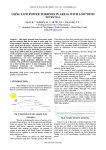
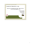
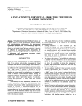
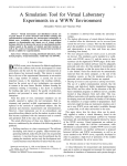
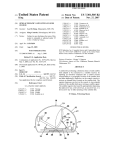
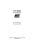
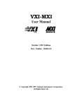
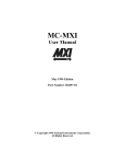
Journal of ELECTRICAL ENGINEERING, VOL. 55, NO. 1-2, 2004, 50–56
REVIEWS - LETTERS - REPORTS
VIRTUAL INSTRUMENTATION AND
DISTRIBUTED MEASUREMENT SYSTEMS
Viktor Smieško — Karol Kováč
∗
The development and use of programmable measurement systems have been widely explored. The possibility of modifying
the measurement procedure simply by changing the algorithm executed by the computer-based architecture without replacing
the hardware components makes the experimental activity easier. Virtual measurement systems have been introduced
to simplify the design, implementation and use of programmable measurement systems by adopting a visual interface.
Networking has also been introduced successfully in measurement to interconnect different instruments and data processing
sites into a distributed measurement system (DMS). Industries that develop and use DMS are migrating away from
proprietary hardware and software platforms in favour of open systems and standardized approaches.
K e y w o r d s: virtual instrumentation, distributed measurement system, remote and networked measurement, interconnect buses.
1 INTRODUCTION
For many years electronic instruments have been easily
identified products. Although they ranged in size and
functionality, they all tended to be box-shaped objects
with a control panel and a display. Stand-alone electronic
instruments are very powerful, expensive and designed to
perform one or more specific tasks defined by the vendor.
However, the user generally cannot extend or customize
them. The knobs and buttons on the instrument, the
built-in circuitry, and the functions available to the user,
all of these are specific to the nature of the instrument. In
addition, special technology and costly components must
be developed to build these instruments, making them
very expensive and hard to adapt.
Widespread adoption of the PC over the past twenty
years has given rise to a new way for scientists and engineers to measure and automate the world around them.
One major development resulting from the ubiquity of the
PC is the concept of virtual instrumentation. A virtual
instrument consists of an industry-standard computer or
workstation equipped with off-the-shelf application software, cost-effective hardware such as plug-in boards, and
driver software — which together perform the functions of
traditional instruments. Today virtual instrumentation is
coming of age, with engineers and scientists using virtual
instruments in literally hundreds of thousands of applications around the globe, resulting in faster application
development, higher quality products and lower costs.
Virtual instruments represent a fundamental shift
from traditional hardware-centred instrumentation systems towards software-centred systems that exploit the
computing power, productivity, display and connectivity
capabilities of popular desktop computers and workstations.
Although PC and integrated circuit technologies experienced significant advances in the past two decades, it is
the software that makes possible building virtual instruments on this foundation. Engineers and scientists are no
longer limited by traditional fixed-function instruments.
Now they can build measurement and automation systems that suit exactly their specific needs.
2 THE CONCEPTION OF
VIRTUAL INSTRUMENT
Usually instrumentation manufacturers provide specific functions to given architecture and fixed interfaces
for measuring devices, and thus limit the application domain of these devices. In actual use much time is required
for adjusting the measuring range and for saving and documenting the results.
The advent of microprocessors in the measurement
and instrumentation fields produced rapid modifications
of measuring device technology, soon followed by the
appearance of computer-based measurement techniques.
Conceptual model of early-computerized instrumentation
is given in Fig. 1.
A single user controls the system, which runs exclusively on a piece of hardware. There is a single control
structure, which is formed by the combination of the user
and the program that controls the multiple devices attached to the instrumentation bus. The main challenges
are the device coupling and the programming models.
The measurement consists of three parts, as shown
in Fig. 2, acquisition of measurement data or signals,
conditioning and processing of analysis of measurement
signals and presentation of data.
The concept of virtual instrument is frequently used
in industrial measurement practice, but not always with
precisely the same meaning. For some people, virtual instruments are based on standard computers and represent systems for storage, processing and presentation of
∗ Department of Measurement, Slovak University of Technology,Ilkovičova 3, 812 19 Bratislava, Slovakia
c 2004 FEI STU
ISSN 1335-3632 51
Journal of ELECTRICAL ENGINEERING, VOL. 55, NO. 1-2, 2004
PROGRAM
USER
DEVICE
DRIV ER
INSTRUMENTATION BUS
DEVICE 1
DEVICE 2
DEVICE n
PROCESS
Fig. 1. Conceptual model of early computerized instrumentation
SIGNALS
ACQUISITION
AND
INSTRUMENT
CONTROL
PRESENTATION
PROCESSING
OR
ANALYSIS
Fig. 2. The diagram of measurement process
ADDED
HARDWARE
SIGNAL
GENERATION
P
C
ADDED
SOFTWARE
DATA
PROCESSING
DATA
ACQUISITION
DATA
PRESENTATION
Fig. 3. The general conception of virtual instrument
measurement data. For others, a virtual instrument is a
computer equipped with software for a variety of uses including drivers for various peripherals, as well as analogue
to digital and digital to analogue converters, representing
an alternative to expensive conventional instruments with
analogue displays and electronics. Both views are more
or less correct. Acquisition of data by a computer can be
achieved in various ways and for this reason the understanding of the architecture of the measuring instrument
becomes important.
A virtual instrument can be defined as an integration
of sensors by a PC equipped with specific data acquisition hardware and software to permit measurement data
acquisition, processing and display.
A virtual instrument can replace the traditional front
panel equipped with buttons and display by a virtual
front panel on a PC monitor. Virtual instruments are a
means of integration of the display, control and centralization of complex measurement systems.
Industrial instrumentation applications, however, require high rates, long distances, and multi- vendor instrument connectivity based on open industrial network
protocols.
In order to construct a virtual instrument it is necessary to combine the hardware and software elements
which should perform data acquisition and control, data
processing and data presentation in a different way to
take maximum advantage of the PC. It seems that in the
future the restrictions of instruments will move more and
more from hardware. Such a general conception of virtual
instrumentation is presented in Fig. 3.
The vendor of virtual instrument can use the serial
communication based on RS-232 standard or the parallel
communication based on GPIB standard (known also as
HP-IB, IEEE 488.1-2 or IEC 625.1-2), PC bus, or VXIbus (VME eXtension for Instrumentation).
The main categories of virtual instruments:
a) Graphical front panel on the computer screen to control the modules or instruments
a1) controlled module is plug-in DAQ board,
a2) controlled instrument is based on GP-IB board,
a3) controlled instrument is connected via serial port,
a4) controlled instrument is VXI-board (or system).
b) Graphical front panel with no physical instruments at
all connected to the computer. Instead, the computer
acquires and analyses the data from files or from other
computers on a network, or it may even calculate its
data mathematically to simulate a physical process or
event rather than acquiring actual real world data.
To the PC connections according to point a) the following process measuring devices are attached:
– Sensors
– GP-IB instruments
– Serial instruments
– VXI instruments
This structure is a result of international standardization
allowing more freedom in using boards and instruments
from various manufactures.
The main representative features of virtual instruments describing their functionality are following:
– Enhancing traditional instrument functionality with
computers;
– Opening the architecture of instruments;
– Widespread recognition and adoption of virtual instrument software development frameworks.
3 BASIC COMPONENTS OF
VIRTUAL INSTRUMENTS
The basic components of all virtual instruments include a computer and a display, the virtual instrument
software, a bus structure (that connects the computer
with the instrument hardware) and the instrument hardware.
52
V. Smieško — K. Kováč: VIRTUAL INSTRUMENTATION AND DISTRIBUTED MEASUREMENT SYSTEMS
Driver level software
PC
DAQ
BOARD
GP - IB
BOARD
SENSORS
SERIAL
PORT
MXI
BOARD
„SERIAL“
INSTRUMENTS
GP - IB
INSTRUMENTS
VXI
INSTRUMENTS
PROCES
Fig. 4. Structure of the PC-based instrumentation hardware
One of the most important components in measurement systems today is the device driver software. Device
drivers perform the actual communication and control
of the instrument hardware in the system. They provide
a medium-level easy-to-use programming model that enables complete access to complex measurement capabilities of the instrument.
In the past programmers spent a significant amount
of time writing this software from scratch for each instrument of the system. Today, instrument drivers are delivered as modular, off-the-shelf components to be used in
application programs. Several leading companies formed
(in 1988) the Interchangeable Virtual Instrument (IVI)
Foundation. The IVI Foundation was formed to establish
formal standards for instrument drivers and to address
the limitations of the former approaches.
3.1 Computer and Display
The computer and the display are the heart of virtual
instrument systems. These systems are typically based
on a personal computer or workstation with a highresolution monitor, a keyboard, and a mouse. It is important for the chosen computer to meet the system requirements specified by the instrumentation software packages.
Rapid technological advancements of PC technology
have greatly enhanced virtual instrumentation. Moving
from DOS to Windows gave to PC users the graphical user interface and made 32-bit software available for
building virtual instruments. The advances in processor
performance supplied the power needed to bring new applications within the scope of virtual instrumentation.
Faster bus architectures (such as PCI) have eliminated
the traditional data transfer bottleneck of older buses
(ISA). The future of virtual instrumentation is tightly
coupled with PC technology.
3.2 Software
If the computer is the heart of the virtual instrument
systems, the software is their brain. The software uniquely
defines the functionality and personality of the virtual
instrument system. Most software is designed to run on
industry standard operating systems on personal computers and workstations. Software implemented can be
divided into several levels, which can be described in a
hierarchical order.
Register level software
Register-level software requires the knowledge of inner
register structure of the device (DAQ board, RS 232 instrument, GP-IB instrument or VXI module) for entering
the bit combination taken from the instruction manual
in order to program measurement functions of the device. It is the hardest way in programming. The resulting
program is strongly hardware dependent and it is rarely
executable on systems with different hardware.
High-level tool software
Currently the most popular way of programming is
based on the high-level tool software. With easy-to-use integrated development tools, design engineers can quickly
create, configure and display measurements in a userfriendly form, during product design, and verification.
The most known, popular tools are as follows:
• LabVIEW (Laboratory Virtual Instrument Engineering Workbench) — is a highly productive graphical programming language for building data acquisition and instrumentation systems. To specify the system functionality one intuitively assembles block diagrams — a natural design notation for engineers. Its tight integration
with measurement hardware facilities rapid development
of data acquisition, analysis and presentation of solutions.
• LabWindows/CVI (C for Virtual Instrumentation) —
is a Windows based, interactive ANSI C programming
environment designed for building virtual instrumentation applications. It delivers a drag-and-drop editor for
building user interfaces, a complete ANSI C environment
for building test program logic, and a collection of automated code generation tools, as well as utilities for building automated test systems and monitoring applications
of laboratory experiments. The main power of CVI lies in
the set of libraries.
• HP VEE (Hewlett-Packard’s Visual Engineering Environment) — allows graphical programming for instrumentation applications. It is a kind of Visual Engineering
Environment, an iconic programming language for solving engineering problems. It also provides an opportunity
to gather, analyze and display data without conventional
(text-based) programming.
• TestPoint — is a Windows based object-oriented software package that contains extensive GPIB instrument
and DAQ board support. It contains a novel state-ofthe art user interface that is easy to use. Objects, called
“stocks” are selected and dragged with a mouse to a work
Journal of ELECTRICAL ENGINEERING, VOL. 55, NO. 1-2, 2004
area (panel). Logic flow is easily established with a point
and drag action list. TestPoint takes advantage of every
Microsoft Windows features.
• Measurement Studio — is a measurement tool for data
acquisition, analysis, visualization and Internet connectivity. This development tool helps you build your test
system by integrating into your existing Microsoft compiler. Measurement Studio provides a collection of controls and classes designed for building virtual instrumentation systems inside Visual Basic or Visual C++. With
Measurement Studio you can configure plug-in data acquisition boards, GPIB instruments, and serial devices
from property pages without writing any code. With
user interface components you can configure real-time 2D
and 3D graphs, knobs, meters, gauges, dials, tanks, thermometers, binary switches, and LEDs. With powerful Internet components, you can share live measurement data
among applications via the Internet.
SCPI — Standard commands for programmable
instruments
SCPI is not a software tool as are former systems, but
it is an effective aid enabling easy standardised control of
programmable instruments. SCPI decreases development
time and increases a readability of test programs. SCPI
provides an easy understandable command set, guarantees a well-defined instrument behaviour under all conditions, which prevents unexpected instrument behaviour.
Although IEEE 488.2 is used as basis of SCPI, it defines
programming commands that we can use with any type
of hardware or communication link. It has an open structure. The SCPI Consortium continues in adding commands and functionality to the SCPI standard.
Real-time and embedded control has been long the
domain of specialised programs. Advances in industrystandard technologies including more reliable operating
systems, more powerful processors and computer-based
real-time engineering tools are introducing new levels of
control and determinism to virtual instrumentation. This
presents new opportunities for scientists to take on increasingly sophisticated real-time and embedded development. Software scales across development on the PC into
development in real-time and embedded applications. Scientists and engineers can move into new application areas
without a steep learning curve because the software itself
evolves to incorporate emerging computer technologies.
3.3 Interconnect Buses
Four types of interconnect buses dominate the industry: the serial connection (serial port), the GPIB, the PC
bus and VXI bus.
Serial port. Serial communication based on RS-232
standard is the simplest way of using a computer in measurement applications and control of instruments. Serial
communication is readily available via the serial port of
any PC and it is limited in data transmission rate and distance (up to 19.2 Kbytes/sec, recently 115 Kbytes/sec,
53
and 15 m) and it allows only one device to be connected
to a PC.
GPIB. It was the first industry standard bus for connecting computers with instrumentation. A major advantage
of GPIB is that the interface can be embedded on the
rear of a standard instrument. This allows dual use of
the instrument: as a stand-alone manual instrument or
as a computer-controlled instrument. Because of this feature, there are a wide variety of high-performance GPIB
instruments to choose from. The GPIB offers a flexible
cable that connects a GPIB interface card in the computer to up to 15 instruments over a distance of up to
twenty meters. The interface card comes with software
that allows transmission of commands to an instrument
and reading of results. Each GPIB instrument comes with
a documented list of commands for initiating each function. Typically, there is no additional software delivered
with the instrument. GPIB has a maximum data rate
of 1 Mbytes/s and typical data transfers are between 100
and 250 Kbytes/s. It depends on the response of the measured subject.
PC-bus. With the rapid acceptance of the IBM personal computer in test and measurement applications,
there has been a corresponding growth of plug-in instrumentation cards that are inserted into spare slots. However, high-accuracy instruments require significant circuit board space to achieve their intended precision. Because of the limited printed circuit board space and close
proximity to sources of electromagnetic interference, PC
bus instruments tend to be of lower performance than
GPIB instruments but also of lower cost. Many are simple
ADCs, DACs, and digital I/O cards. PC bus instrumentation is best suited for creating small, inexpensive acquisition systems where the performance is not of paramount
importance. Since these cards plug directly into the computer backplane and contain no embedded command interpreter as found in GPIB instruments, personal computer plug-in cards are nearly always delivered with driver
software so that they can be operated from a personal
computer. This software may or may not be compatible with other virtual instrument software packages, so
it is recommended to check with the vendors beforehand.
Most data acquisition boards are multifunctional, ie they
accept both analogue and digital signals. These plug-in
data acquisition boards gain wider and wider acceptance
due to their low price and high flexibility obtained from
the associated software.
VXI bus. In the late eighties, the VME eXtension for
Instrumentation (VXI) standard allowed communication
among units with transfer over 20 Mbytes/second between VXI systems. VXI instruments are installed in a
rack and are controlled by, and communicate directly
with, a VXI computer. These VXI instruments do not
have buttons or switches for direct local control and do
not have local display typical in traditional instruments.
It is an open-system instrument architecture that combines many of the advantages of GPIB and computer
backplane buses. VXIbus instruments are plug-in modules that are inserted into specially designed card cages
54
V. Smieško — K. Kováč: VIRTUAL INSTRUMENTATION AND DISTRIBUTED MEASUREMENT SYSTEMS
GPIB
Controller
To another
GPIB
instrument
MXI
VXI Mainframe
VXI Mainframe
GPIB
VXI
INST
#1
INST
#2
RAM
...
INST
#3
CPU
Fig. 5. A VXIbus system controlled by GPIB
UNK
MXI
VXI
INST
#1
INST
#2
...
RAM
INST
#3
CPU
Fig. 6. A VXIbus system controlled over a high-speed MXIbus
cable
VXI Mainframe
PC
INST
#1
...
INST
#2
RAM
...
INST
#3
INST
#4
Fig. 7. A VXIbus system controlled by an embedded VXIbus
computer inserted into the mainframe
known as “mainframes”. Mainframes include power supplies, air cooling equipment and backplane communication for the modules. The VXIbus is unique in that it
combines a computer backplane based on the VME-bus
for high-speed communication and offers a quality EMC
environment that allows high-performance instrumentation similar to that found in GPIB. As a result, much
more compact measuring systems can be built.
There are three ways to communicate between the
computer and the VXI bus instruments.
a) The first method is by using GPIB. In this case, a
GPIB to VXIbus converter module is plugged into the
VXIbus mainframe and a standard interface cable connects it and the GPIB interface card in the computer.
The advantages and disadvantages of this technique
are very similar to a pure GPIB design. This system
tends to be easy to program, but data speeds are limited to GPIB speeds. However, because the internal
data speeds within the VXIbus mainframe can exceed
10 Mbytes/s, often a high-speed application is solved
by local high-speed acquisition and processing occurring within the mainframe and high level results transfer to the computer over GPIB. Figure 5 shows an example of VXIbus system using GPIB.
b) The second technique is to use a higher-speed interconnect bus between the VXIbus mainframe and the
computer. The most common implementation of this is
a high-speed flexible-cable interface known as MXIbus.
As in GPIB, an MXIbus interface card and software
are installed on the computer and a cable attaches it to
an MXIbus to VXIbus converter module in the VXIbus
mainframe. MXIbus is essentially an implementation
of the VXIbus on a flexible cable. This means that the
conversions to VXIbus are simple and fast, bringing
MXIbus performance within a factor of 2 or so of native VXIbus speeds. The advantage of MXIbus is that
it allows the use of off-the-shelf computers to communicate with VXIbus instruments at a speed considerably higher than GPIB. A disadvantage is that the
MXIbus cable can be thick and unwieldy, and there is
some loss of data-transfer bandwidth due to the conversion. Figure 6 shows an example VXIbus system
using MXIbus.
c) The third way is to insert powerful VXIbus computers
directly into the VXIbus mainframe. VXIbus computers tend to be repackaged versions of industry standard
personal computers and workstations that run industry standard operating systems and software. The advantage of this technique is that it preserves the full
communications performance of VXIbus. The disadvantage is that the choice of VXIbus computers will
always be a subset of the choice of standard industry
computers. VXIbus computer technology will typically
lag behind the performance of the industry as a whole,
offer fewer alternative configurations and be priced at
a premium due to its lower volume. Figure 7 shows an
example VXIbus system using an embedded computer.
3.4 Instrument Hardware
The preceding subsection on interfaces also touches on
the attributes found in each of the respective instrument
hardware products. One note is worth to be repeated:
Virtual instrumentation never eliminates the instrument
hardware completely. To measure the real world there will
always be some sort of measurement hardware, sensor,
transducer and conditioning circuit, but the physical form
factor of this instrumentation may continue to evolve.
4 DISTRIBUTED MEASUREMENT SYSTEMS
The present trend in interconnected measurement systems is to extend the area covered by the interconnected
systems in the geographical scale. This sets a further limit
55
Journal of ELECTRICAL ENGINEERING, VOL. 55, NO. 1-2, 2004
FILE
SERVER
TERMINAL
1
TERMINAL
2
TERMINAL
3
LAN
CONTROLLER
GPIB
CONTROLLER
DAQ
CONTROLLER
RS 232
CONTROLLER
VXI
MXI
GPIB
INSTRUMENT
3
INSTRUMENT 5
INSTRUMENT
2
INSTRUMENT 4
INSTRUMENT
1
RS232
...
MXI
VXI
Fig. 8. Block diagram of distributed measurement system based
on LAN
DISPLAY
FILES
FTP
INTERNET
EXPLORER
DATA
SOCKET
CONTROLL
URL
Fig. 9. The architecture of a distributed system based on Internet
to the use of such systems. As in the case of large and complex plants, a structured networked measurement system
can be adopted by scaling its use to the geographical area.
The geographical process to be monitored and controlled
is partitioned into cells that can be dealt with by a single processing unit or a group of locally connected units.
Geographically distributed units are connected by a geographical computer network into a distributed measurement system. In this case communication delays usually
cannot be neglected. This is even more relevant if the traffic in the computer network is not negligible due to the
number of computers connected and the amount of communications, especially if a public computer network is
used to realise the interconnections among the measuring
processing units.
It seems that in the near future local network (LAN)
can be considered as a kind of measurement bus, from
the viewpoint of measurement and control systems. A
typical example of such a system including various virtual
instruments is presented in Fig. 8. It can be considered
as a first step to a wider, Internet based technology.
In the last few years a surprisingly rapid growth of fast
and reliable communication networks has allowed an easy
interchange of information and commands between computers both connected to local networks and connected
to faraway site of wide area networks (WAN), such as
the Internet. Thus, network services and programmable
instrumentation now permit the development of measurement laboratories distributed on a wide geographical area
and simultaneously available to several users variously located in the territory.
Common Internet-based software can be used to provide easy data migration between various communication
pathways. Multi-computer processing systems are effective in creating complex systems by overcoming limitations of a single computer concerned with the overall computing power or the number of signals to be acquired and
processed.
Standard software languages such as C and Java can
be used with off-the-shelf development tools to implement
the embedded network node applications and the webbased applications respectively. Internet based TCP/IP
protocols, Ethernet technology and/or DataSockets can
be used to design the networking infrastructure, Fig. 9.
DataSocket is a software technology for Windows that
makes sharing all measurements across a network (remote
Web and FTP sites) as easy as writing information to a
file. It uses URLs to address data by the same way we use
URL in a Web browser to specify Web pages. DataSocket
included with any software tool is ideal when someone
wishes to complete control over the distribution of the
measurement but does not want to learn the intricacies
of the TCP/IP data transfer protocols.
In all types of networked and distributed measurement
systems presented above, real-time operation and constraints are critical issues to be considered during system
design to ensure the correct system operation.
With distributed measurement system one can take remote measurements, distribute a program’s execution, or
publish measurement data over the Internet. The evolved
hardware and software technologies provide users with
the tools they need for easy building of a powerful distributed system.
By publishing your measurement or automation application over the Internet real-time data can be viewed
by users on remote computers. With application development environments Web servers are available so you can
publish a user interface to the Internet. Without any additional programming you can publish your front panel
as a Web page so users across the Internet can view these
panels running within any standard Web browser.
Applications have one or more measurement nodes
physically separated from the computer that is controlling them and collecting data. Remote measurement applications often require high speed streaming of
data and several clients connected to a single measurement. For streaming measurement data across a network
DataSocket provides you with an easy-to-use interface.
Using DataSocket you can easily stream any kind of measurement data across a local area network or the Internet to several client programs. Both Web servers and
DataSocket provide a simple and convenient way to publish your measurement data.
5 CONCLUSIONS
Virtual instrumentation is fuelled by ever-advancing
computer technology and it offers the power of creating
and defining someone’s own system based on an open
framework. The combination of computer performance,
graphical software, and modular instrumentation has led
56
V. Smieško — K. Kováč: VIRTUAL INSTRUMENTATION AND DISTRIBUTED MEASUREMENT SYSTEMS
to the emergence of virtual instruments, which are substantially different from their physical ancestors. Virtual
instruments are manifested in different forms ranging
from graphical instrument panels to complete instrument
systems. Modular instrumentation building blocks are becoming more prevalent in the industry and are allowing users to develop capabilities unattainable using traditional instrument architectures. Despite these changes
however, the measurement paradigm remains unaltered.
This might be the proper platform for the new development.
The trend in virtual instrumentation increasingly integrates the measurement systems into more complex monitoring and control systems distributed over different (possibly geographically distant) locations. The remote instrumentation control is becoming popular since the networks have become reliable and world wide and almost
every new instrument embeds programmable capabilities.
The past has shown that unless proper standards are
available, diversification due to ad-hoc solutions will slow
the progress in the field. Thus, it seems a proper challenge for the future to start thinking of standardization
of virtual instrumentation and distributed measurement
systems.
References
[13] TAN, K. K.—SOH, C. Y. : Instrumentation on the Internet,
Engineering Science and Education Journal IEE 10 No. 2 (2001),
61–67.
[14] FERRERO, A.—PIURI, V. : A Simulation Tool for Virtual
Laboratory Experiments in a WWW Environment, Proc. IEEE
Conf. on Instrumentation and Measurement Technology, St.
Paul, Minnesota, USA, 18–21 May 1998, 1, 102–107.
[15] SCPI: Standard Commands for Programmable Instruments, version 1991.0, May 1991.
[16] ni.com/dvi.
[17] SMIEŠKO, V.—KOVÁČ, K.—KAZIČKA, R. : VXI-bus as a
Tool for Dynamic Testing, Proc. Int. Conf. CATE 93, Brno,
1993, 283–287.
[18] ANSI/IEEE Std. 488.1 — 1987, IEEE Standard Digital Interface
for Programmable Instrumentation.
[19] ANSI/IEEE Std. 488.2 — 1987, IEEE Standard Codes, Formats,
Protocols and Common Commands.
[20] SMIEŠKO, V. : Some Properties of VXI System in Relation to
HP-IB, Proceedings Precise Measurement in Army. Brno, 1991,
68–71.
[21] VXI-bus System Specification, Revision 1.3, Tektronix.
[22] ONDRÁŠOVÁ, I.—SMIEŠKO, V.—SETNIČKA, V. : Contribution to the Efficiency of GPIB Instrumentation. In: Measurement Science Review. Vol. 1, No. 1, 2001, 59–62.
[23] HELSEL, R. : Visual Programming for PH VEE, Prentice Hall
PTR, 1997.
[24] HP VEE for Windows User Manual, Hewlett-Packard Corp.,
1993.
[25] LabWindows/CVI User Manual, National Instr. Corp., Austin
1994.
[26] Test Point Demo System, Keithley Instruments, 1992.
[27] EREN, H.—NICHOLS, W. J.—WONGSO, I. : Towards an
Internet-Based Virtual-Wire Environment with Virtual Instrumentation. IEEE Instrumentation and Measurement, Conference, Budapest, Hungary, May 21–23, 2001, 817–820.
[28] JASENEK, J. : Sensors with Distributed Parameters on the
Basis of POTDR, Journal of Electr. Eng 53 No. 9/s (2002),
101-106, Presented at XVI-th International Conference EMFM,
Bratislava, Sept. 11-13, 2002.
[1] CRISTALDI, L.—FERRERO, A.—PIURI, V. : Programmable
Instruments, Virtual Instruments and Distributed Measurement Systems. IEEE Instrumentation & Measurement Magazine, Sep., 1999, 20–27.
[2] BAICAN, R.—NESCULESCU, D. : Applied Virtual Instrumentation, WIT Press, Boston, 2000.
[3] GOLDBERG, H. : What is Virtual Instrumentation? IEEE
Instrumentation & Measurement Magazine, December 2000,
[29] KAZIČKA, R., ONDRÁŠOVÁ, I.—SMIEŠKO, V. : Improving
10–13.
the AT&MS Parameters, J. Electrical Engineering 46 No. 7
[4] SPOEDLER, H. J. W. : Virtual Instruments and Virtual En(1995), 261–264.
vironments. IEEE Instrumentation & Measurement Magazine,
[30]
ONDR
ÁŠOVÁ, I.—SETNIČKA, V.—SMIEŠKO, V. : AutoVol. 2, 1999, 14–19.
mated
Instrumentation Application. In: 12th International Sci[5] SMIEŠKO, V.—KUKUČA, P. : Measurement on the Threshold
entific
Conference “Rádioelektronika 2002”, Bratislava, Slovak
of the Third Millennium, J. Electrical Engineering 52 No. 7-8
Republic, 14–16 May 2002, 182–185.
(2001), 240–243.
[6] TRUCHARD, J. : Future of Virtual Instrumentation, NI Week,
Received 17 October 2003
2002.
Viktor Smieško (Prof, Ing, CSc) was born in Zlatovce,
[7] DES-JARDIN, L. : Virtual Instruments and the Role of Software. Electronic Instrument Handboock. McGraw-Hill, 1995, Czechoslovakia, in 1948. He graduated with honors in 1970
44.1–44.14.
and received the CSc (PhD) degree at the Faculty of Elec[8] GALWAS, B. A.—RAK, R. J. : Virtual Laboratory — a Fu- trical Engineering, Slovak Technical University. Currently is
ture Part of the New Web-Based Model of Undergraduate Engi- Full Professor for Instrumentation at the Faculty of Electrical
neering Studies Developed by Warsaw University of Technology. Engineering and Information Technology, Slovak University
Joint IMEKO TC-1 & XXXIV MKM Conference 2002, Wroclaw,
of Technology. His research interests are in the areas of auto8-12 September, 2002.
mated instrumentation and electromagnetic compatibility.
[9] McCONNELL, E. : The Future of Virtual Instrumentation. SenKarol Kováč (Doc, Ing, CSc) was born in Bratislava, Slosors, July 1997, 237–240.
vakia on June 9, 1952. He received the Ing (MSc) degree with
[10] EPPLER, B. : A Beginners Guide to SCPI, Addison-Wesley
honors in 1976 and the CSc (PhD) degree in electrical engiPublishing Company Inc., 1999.
neering from the Faculty of Electrical Engineering of the Slo[11] BERTOCCO, M.—FERRARIS, F.—OFFELLI, C.—PARVIS,
M. : A Client-Server Architecture for Distributed Measurement vak Technical University, Bratislava. Since 1976 he has been
Systems, IEEE Transactions on Instrumentation and Measure- with the Department of Measurement of the Faculty of Electrical Engineering and Information Technology, Slovak Uniment 47 No. 5 (1998), 1143–1148.
[12] LEE, K. B.—SCHNEEMAN, R. D. : Internet-Based Distributed versity of Technology, now as Associate professor for Electric
Measurement System and Control Application, IEEE Instru- Measurement. His research interests are in the area of commentation & Measurement Magazine, June 1999, 23–27.
puter modelling and measurement of ESD pulse processes.