1
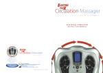
Instructions
Thank you for purchasing the ElectroVita Circulation Enhancer.
Helps reduce stresses and aches with the amazing ElectroVita Circulation Enhancer from
JML. Simply place your feet on the footpads, set the intensity level and sit back. Low
frequency micro-currents safely stimulate the reflex points in your feet, waking up tired
nerves, muscles and capillaries. Capillaries are the smallest of your bodies blood vessels and
provide the exchange between cells and circulation.
So relax and re-energise with the ElectroVita Circulation Enhancer.
Contents
Quick start guide
Important Safety Information
03-06
What is Electronic Nerve Stimulation?
07
Machine Overview and Part Names
08
Functions and Programmes
09
Electroflex Output Wave Forms
10-11
How to Operate
12-14
Cleaning
1
02
15
Troubleshooting and Maintenance
16-17
Important information
18-21
Quick Start Guide
For detailed operation of your ElectroVita™ Circulation Enhancer Electrical Stimulator please
refer to the comprehensive instructions within this manual.
To use the Circulation Enhancer immediately follow this 5 point quick start guide.
1. Remove your ElectroVita Circulation Massager from the
packaging. Connect the DC adapter to a suitable mains
outlet and plug the small DC socket into the device.
2. Turn on the power the central display will light up blue for
2-3 seconds and then turn off again, this is normal. Hold
down the central power switch for 3-4 seconds. The main
display will light up blue and remain on.
3. Remove your footwear and socks or stockings. Your feet
need to be completely bare to experience the
ElectroVita micro current stimulation massage therapy.
PROGRAM
4. There are 10 different treatment programmes, each
offering a range of micro-current massage therapies.
Select a number from 1 - 10 by pressing the P+ and P–
buttons. We suggest you try all 10 over time to decide
which best suits you.
PROGRAM
5. Sit in a comfortable chair. Place your bare feet on the left
and right foot plates. Increase the intensity levels for
each foot by pressing the
and
to increase the intensity
to decrease for BAND 1. The intensity level ranges
from 0 to 40, slowly increase the level until you begin to
feel the micro-current stimulation.
For a full explanation of setting the intensity refer to page 13.
2
Important safety information
1. Please read these instructions thoroughly before use.
2. Please check that you have all of the component parts as detailed in this user manual.
3. Take all parts out of the plastic bags and examine them to familiarise yourself with the components.
Notes on Safety
The icons and warning signs are indicated here for your safety and correct usage of the
product as well as to prevent injuries and/or damage to properties.
The icons and meanings are as follows:
Examples of Icon
This icon means prohibited (must not do).
Anything prohibited is marked clearly with this warning symbol.
This icon indicates something that is compulsory
(must be observed). Compulsory actions are marked clearly with this warning symbol.
This product should not be used by persons with
electronic medical implants, e.g. heart
pacemakers, organ transplant or other electronic
life support systems.
Disposal of this product and used batteries
should be carried out in accordance with the
national regulations for the disposal of electronic
products. Directive 2002/96/EC(WEEE).
Consult instructions for use
Date of manufacturer
Manufacturer’s name
Batch Code
Authorised representative in the European Community.
Class II equipment
Caution, consult accompanying documents
Type BF applied Part
This symbol means serial number which is on the
underside of the device and on the packaging.
CE Mark: conforms to essential requirements of
the Medical Device Directive 93/42/EEC
3
Important safety information
Danger
This unit must not be used in combination with the following medical devices:
t*OUFSOBMMZUSBOTQMBOUFEFMFDUSPOJDNFEJDBMEFWJDFTFHQBDFNBLFST
t&MFDUSPOJDMJGFTVQQPSUFRVJQNFOUTVDIBTSFTQJSBUPST
t&MFDUSPOJDNFEJDBMEFWJDFTBUUBDIFEUPUIFCPEZTVDIBTFMFDUSPDBSEJPHSBQIT
Using this unit with other electronic medical devices may cause erroneous operation of those devices.
Warning
Persons with the following conditions must consult the doctor before using this unit:
t"DVUFEJTFBTFt.BMJHOBOUUVNPSt*OGFDUJPVTEJTFBTFt1SFHOBODZt$BSEJBD
EZTGVODUJPOt)JHIGFWFSt"COPSNBMCMPPEQSFTTVSFt4LJOTFOTPSZEJTPSEFSTPSTLJO
QSPCMFNTt3FDFJWJOHNFEJDBMUSFBUNFOUFTQFDJBMMZUIPTFGFFMJOHEJTDPNGPSU
May cause an accident or ill health. Should not be used by persons in the first trimester
of pregnancy, fitted with a pacemaker or AICD, or being treated for an existing deep
vein thrombosis Do not use this unit near the heart, above the neck, on the head,
around the mouth or on diseased skin.
May cause an accident or ill health.
Application of electrodes near the thorax may increase the risk of cardiac fibrillation.
Do not use this unit simultaneously with other therapeutic devices or in combination with
ointments including spray type ointments.
May cause discomfort or ill health.
Simultaneous connection of a PATIENT to h.f. surgical EQUIPMENT may result in burns at
the site of the STIMULATOR electrodes and possible damage to the STIMULATOR.
Operation in close proximity (e.g. 1 m) to a shortwave or microwave therapy EQUIPMENT
may produce instability the STIMULATOR output. Do not use this unit for purposes other
than treatment indicated in this manual. May lead to accident, problems, or failure of the unit.
Do not insert the electrode cord plug into any place other than the electrode cord jack of the
main unit. May cause an electric shock or accident.
Do not disassemble or remodel this unit. May cause fire, dysfunction, or accident.
Caution
If the unit is not functioning properly or you feel discomfort, stop using the unit
immediately.
If you feel any problems with your body or skin, consult your medical practitioner and
follow their instructions. If you want to move the Electrode Pad to another region or
your body during treatment, be sure to turn off the power. If not, you may receive
a strong electrical shock. Do not try to attach the Pads to any other person during
the treatment. You may receive strong electrical shock. Do not start treatment while
wearing an electronic device. The settings and timings of the device may be affected.
Do not use in the presence of flammable anaesthetic gas mixture with air, oxygen or
nitrous oxide.
4
Important safety information
Do not use this unit on infants or people not capable of expressing their
intentions.
May cause an accident or ill health.
Do not use this unit in places with high humidity such as bathrooms or while taking
a bath or shower. You will receive a strong electrical shock.
Do not use this unit while sleeping. The main unit may develop a malfunction, or the pad
may
move to an unexpected region and cause ill health.
Do not use this unit while driving. Receiving sudden strong stimulation may lead to traffic
accident.
Do not leave the Electrode Pad attached to the skin after treatment. Prolonged
attachment may cause skin irritation or infection.
Be careful not to allow any metal object, such as a belt buckle or necklace to
come into contact with the Electrode Pad during treatment. You may receive a strong
electrical shock.
Do not use cellular phones or other electronic devices near this unit.
Do not use this unit to treat one region for a long time (more than 25 minutes).
The muscles of the region under treatment may become exhausted and may cause poor
physical condition.
Put the Long Life pads only on skin or on the storage tray to avoid damage of the
adhesive surfaces of the pads.
Correct Disposal of This Product (WEEE Waste Electrical and Electronic Equipment)
This marking shown on the product or its literature, indicates that it should not be disposed
of, with other household wastes at the end of its working life. To prevent possible harm to the
environment or human health from uncontrolled waste disposal, please separate this from
other types of wastes and recycle it responsibly to promote the sustainable reuse of
material resources.
Household users should contact either the retailer where they purchased this product,
or their local government office, for details of where and how they can take this item for
environmentally safe recycling.
Business users should contact their supplier and check the terms and conditions of the
purchase contract. This product should not be mixed with other commercial wastes for
disposal.
This product does not contain any hazardous substances.
Disposal of used batteries should be carried out in accordance with the national regulations
for the disposal of batteries.
5
Important safety information
Important information regarding Electro Magnetic Compatibility (EMC)
With the increased number of electronic devices such as PC’s and mobile (cellular)
telephones, medical devices in use may be susceptible to electromagnetic interference from
other devices. Electromagnetic interference may result in incorrect operation of the medical
device and create a potentially unsafe situation. Medical devices should also not interfere
with other devices.
In order to regulate the requirements for EMC (Electro Magnetic Compatibility) with the aim
to prevent unsafe product situations, the EN 60601-1-2: 2001+A1:2006 standard has been
implemented. This standard defines the levels of immunity to electromagnetic interferences
as well as maximum levels of electromagnetic emissions for medical devices.
This medical device manufactured by TV Products HK Ltd. conforms to this EN 60601-1-2:
2001+A1:2006 standard for both immunity and emissions.
Nevertheless, special precautions need to be observed:
Do not use mobile (cellular) telephones and other devices, which generate strong electrical or
electromagnetic fields, near the medical device. This may result in incorrect operation of the
unit and create a potentially unsafe situation.
Recommendation is to keep a minimum distance of 7m. Verify correct operation of the
device in case the distance is shorter.
BE109 needs special precautions regarding EMC and needs to be installed and put
into service according to the EMC information provided in the ACCOMPANYING
DOCUMENTS.
Portable and mobile RF communications equipment can affect the BE109
(Circulation Enhancer).
WARNING that the use of accessories, transducers and cables other than those supplied
with the exception of the transducers and cables sold by the manufacturer of the BE109
(Circulation Enhancer) as replacement parts for internal components, may result in increased
EMISSIONS or decreased IMMUNITY of BE109 (Circulation Enhancer).
WARNING that BE109 (Circulation Enhancer) should not be used adjacent to or stacked
with other equipment.
6
What is electronic nerve stimulation?
INTENDED USE: Medical Purpose
This Electronic Nerve Stimulator is intended to be used as a massager to relieve (muscle) pain,
increase blood circulation, relax stiffness muscles, reduce swollen feet and ankles and fatigue. The
massaging effect is achieved by electronic stimulation of the nerves through electrode pads placed on
the skin or through the foot plates. Various massage regions and treatment programs can be selected.
Suitable Users: Please read “Notes on safety” before using the unit. (This unit should not be used by
people prohibited from doing so in “Notes on safety”.).
Environment: This unit is intended for home use only. Effectiveness: Massage relief of (muscle) pain,
stiffness and fatigue. Precautions for use: Please read “Notes on safety” before using the unit.
Electronic Nerve Stimulation is a non-invasive, safe nerve stimulation intended to reduce
pain. The ElectroVita Circulation Massager uses proven neuromuscular electrical
stimulation therapy to send micro current pulses through the soles of your feet. This type
of electrical stimulation is clinically proven to be safe and effective and can be carried
out in the comfort of your own home. The ElectroVita Circulation Massager improves
muscle function by stimulating nerves increasing the flow of blood helping to reduce PAIN,
SWELLING, TIRED AND ACHING LEGS Medical Purpose
This Electronic Nerve Stimulator is intended to be used as a massager to relieve (muscle) pain,
increase blood circulation, relax stiff muscles, reduce swollen feet, ankles and relieve fatigue. The
massaging effect is achieved by electronic stimulation of the nerves through electrode pads placed on
the skin or through the foot plates. Various massage regions and treatment programs can be selected.
To obtain a correct treatment you have available 10 treatment programs (see table below). A treatment
program runs for 25 minutes
Mode
7
Complaint
Program
E ect
1
Sti shoulders
Tapping massage
Di erent vibrations promote blood circulation
and relieve fatigue
2
Swelling and
foot fatigue
Prickly massage
Di erent stimulation promote circulation of
blood and body uid in the feet
3
Acute Pain
Combined massage
High frequency vibrations relieve acute
pain promptly
4
Acute elbow or
knee pain
Pulsed prickly massage
High frequency vibrations relieve acute
pain promptly
5
Arm fatigue
Tapping massage (2)
Promote Blood circulation with
di erent stimulation
6
Swelling and
calf fatigue
Fast tapping massage
Di erent stimulation promote circulation of
blood and body uid in the limbs
7
Back pain or lower
back sti ness
Fast tapping/prickly massage
A low frequency to promote blood circulation
and relieve pain (neuralgia)
8
Sti muscles,
numbness
Very fast tapping/prickly massage
A low frequency to promote blood circulation.
This program is e ective over a long period
9
Various Symptoms
Pulse prickly massage (2)
Relieves sti ness, pain and fatigue
10
Various Symptoms
Fast tapping with pulse massage
Relieves sti ness, pain and fatigue
Machine overview and part names
Output for the feet Electrode Silicon Area for
Foot Treatment
LCD Display Screen
Output for Body - for
connecting Gel Pads
(cable jack) for Body
Massage Treatment
Sole Massage
Roller
The EletroFlex Circulation
Massager is also supplied
with an AC/DC Adaptor
(not illustrated)
Adaptor Jack
Cable connecting
the Electrode Gel
Pads and Device
Built-in Ergonomic
Carrying Handle
Electrode Gel Pads to
target speci c areas of
pain and swelling
Additional Sole
Massage Roller
(spare)
Plastic Protector
for Gel Pads
8
Functions and programmes
Control Panel
LCD showing the
Intensity Level
LCD showing the
Intensity Level
for feet – maximum 40
Levels
BAND1
LCD showing the Timer
for body – maximum 40
Levels
BAND2
Min
LCD showing the
Program
PROGRAM
B
Indication from 1 – 10
Modes
F
D
A
E
G
C
A. To switch the unit on or off
B. Choose from one of the 10 pre-programmed massage programs ~ Upward
C. Choose from one of the 10 pre-programmed massage programs ~ Downward
D. Increase the output intensity of foot (BAND 1) FROM 1- 40 LEVEL
E. Decrease the output intensity of foot (BAND 1) FROM 1- 40 LEVEL
F. Increase the output intensity of body (BAND 2) FROM 1- 40 LEVEL
G. Decrease the output intensity of body (BAND 2) FROM 1- 40 LEVEL
Electrode Area
On the device (Figure 1) the black
BAND1
BAND2
Min
colour area on the device which is
PROGRAM
the electrode area for the sole.
On the gel pad (Figure 2), the black
colour area on the sticky part is the
electrode area for the body,
Fig 1
9
size is 5 cm x 9 cm.
Fig 2
Circulation Enhancer output wave forms
Foot Electro Therapy Massage
We will examine the operation in more detail later in your instructions but the principle is
relatively easy to understand. There are two separate controls/channels, one for the feet,
being band 1 and one for the pads being band 2. Place your feet on the foot plates, turn on
ElectroFlex with the central on/off switch (hold down for 3 seconds to activate), choose one
of the 10 different treatment programmes and start to increase the intensity to a comfortable
level. There are 40 different levels. When you start to feel the mild electro-therapy will depend
on your own nerve sensitivity. Certain individuals will feel nothing until the intensity is up at a
high level, others will feel the stimulation at relatively low levels. This is completely normal.
Body Toning
If you choose to tone muscle groups or target pain in other areas of your body the
ElectroFlex comes with four gel pads. These can be used to tone arms, hips, thighs, abs or
buttocks or target neck muscle or back pain.
The Outputs have no DC Component
Output Waveform
BAND 1 SOLE MASSAGER (during 1 kΩ load)
MODE OUTPUT
1
Pulse rate 6Hz with 1 second in left side , right
side o time 1 second then Pulse rate 6Hz with
1 second in right side , left side o time 1
second. A cycle repeating.
BAND 2 BODY MASSAGER (during 1 kΩ load)
MODE OUTPUT
1
Pulse rate 13Hz- 80Hz with 13 seconds and o
time in 1 sec. A cycle repeating.
2
Pulse rate 13Hz- 80Hz with 18 seconds and o
time in 1 sec. A cycle repeating.
2
Pulse rate 12Hz- 80Hz with 12 seconds and o
time in 1 sec. A cycle repeating.
3
Pulse rate 13Hz- 80Hz with 19 seconds and o
time in 1 sec. A cycle repeating.
3
Pulse rate 7Hz with 30 seconds and o time in
1 sec. A cycle repeating.
4
Pulse rate 13Hz- 80Hz with 7 seconds and o
time in 1 sec. A cycle repeating.
4
Pulse rate 7Hz- 25Hz with 8 seconds and o
time in 1 sec. A cycle repeating.
5
Pulse rate 13Hz- 80Hz with 16 seconds and o
time in 1 sec. A cycle repeating.
5
Pulse rate 12Hz- 80Hz with 11 seconds and o
time in 1 sec. A cycle repeating.
6
Pulse rate 13Hz- 80Hz with 10 seconds and o
time in 1 sec. A cycle repeating.
6
Pulse rate 12Hz with 12 seconds and o time in
1 sec. A cycle repeating.
7
Pulse rate 13Hz- 80Hz with 17.6 seconds and
o time in 1 sec. A cycle repeating.
7
Pulse rate 11Hz- 80Hz with 15 seconds and o
time in 1 sec. A cycle repeating.
8
Pulse rate 12Hz with 10 seconds and o time in
1 sec. A cycle repeating.
8
Pulse rate 12Hz with 10 seconds and o time in
1 sec. A cycle repeating.
9
Pulse rate 12Hz with 16 seconds and o time in
1 sec. A cycle repeating.
9
Pulse rate 12Hz with 13 seconds and o time in
1 sec. A cycle repeating.
10
Pulse rate 12Hz- 80Hz with 11 seconds and o
time in 1 sec. A cycle repeating.
10
Pulse rate 12Hz- 80Hz with 10 seconds and o
time in 1 sec. A cycle repeating.
10
ElectroVita output wave forms
11
How to operate
For feet - BAND 1
In order to increase the conductivity we recommend that you dampen the soles
of your feet.
1. Place your bare feet onto ElectroVita (do not wear socks).
2. Press (and hold down for 3 seconds) the on/off button, the LCD screen will light up in blue.
The program will show 01 and both band shows 00, which means the device is in standby
mode. (See Figure 3).
3. Select the program you wish to use, there are 10 different programs which are indicated
on the LCD display. Select the program by pressing “P+” and “P-”. (See Figure 4).
Gently increase intensity setting by holding down the button “ ”. Or decrease intensity
setting by holding down the button “ ”. The intensity level is adjustable between 0 and 40.
(See Figure 7). In order to let the user feel the stimulation gradually increase the intensity to
a comfortable level by holding down the “ ” intensity button. Those who suffer with poor
circulation may not feel anything until reaching a higher level of intensity. There are 40
output levels. When you reach your desired intensity level release the button, the icon will
blink. To stop the blinking and maintain the intensity press the “ ” button 5 times.
4. You can adjust the program anytime. Once re-adjusted the intensity will return to “0”. So
you will have to increase the intensity to the desired level. The LCD will also show the level
which you have selected. (See Figure 5). To terminate the massage period, you can turn off
the unit anytime by pressing the on/off button for 3 seconds. The unit has an auto timer, it will
start to count down from 25 minutes of massage and switch off automatically.
BAND1
BAND2
Min
PROGRAM
Fig 1
Fig 2
Fig 3
12
How to operate
For Body – BAND 2
Using the Gel Pads
Connect the output wire to the gel pads. Connect the other end of the output wire to the
output jack on ElectroFlex. Remove the protective film from the adhesive pads. Attach the
gel pads to the skin. Press the on/off button for 3 seconds to turn on the unit andadjust the
stimulating mode and output intensity to the desired level. (The display will show the mode
and level that you selected and start to count down).
1. Plug the 2 cables into the cable jack at the side of the unit. (See Figure 6).
2. Connect pin of the cable to the gel pad. (See Figure 7).
3. Remove the protective film from the gel pad, and attached the 4 pads to the area of the
body you wish to treat.
4. Repeat operation as in foot instructions, adjust the intensity using Band 2.
5. Gently increase the intensity setting by pushing the button “ ”. Or decrease intensity
setting by pushing the button “ ”. (See Figure 8). The LCD will show the level selected
(see Figure 9). When you reach the desired Level the icon will blink. To stop the blinking and
maintain the intensity press the “ ” button 5 times.
6. To terminate the massage period, turn off the unit a tanytime by pressing the on/off Button
for 3 seconds. The unit has an auto timer, it will start to count down from 25 minutes of
massage and switch off automatically.
If you want to use with 2 gel pads only, then you must connect 1 gel pad to Jack A
and 1 gel pad to Jack B.
Care of your Gel Pads
Never stick two adhesive pads to each other. Keep the adhesive gel pads clean, do
not expose them to high temperature or direct sunshine. If the electrode gel pads are
insufficiently adhesive or dirty, wipe with a damp or change for new ones. Replacement parts
will be available directly from BioEnergiser or your distributor. Do not clean the electrode gel
pads with any chemical. ALWAYS try and protect the gel pads store on the gel
pad protector when not in use, as illustrated.
Shoulder/Back
Thighs
Tummy
Lower back
Arms
BAND1
BAND2
Min
Fig 6
13
Fig 7
Fig 8
Fig 9
How to operate
Connect with the supplied AC/DC Power Adapter
Plug the DC plug of the power supply into the socket on the side of ElectroVita (see Figure
10. Plug in power adaptor to a suitable wall socket. (Make sure that the input voltage of the
wall socket is suitable for the supplied adaptor).
Inserting Batteries
If you want to use the ElectroVita with battery powerinstead of the supplied main adaptor, the
battery compartment is located on the underside of the unit.
Remove the battery cover from the unit by removing the screw with a screwdriver. Insert
three new 1.5V size C batteries with the + and - marks correctly aligned.
Note on batteries: Do not mix different types of batteries or an old battery with a new one.
To prevent the risk of leakage or explosions, never recharge the batteries, apply heat or take
them apart. When not using batteries, remove them to prevent battery drainage. If liquid
leaks from the batteries, throw them away. Thoroughly clean the battery compartment
with a dry cloth.
Changing the Sole Massage Roller
The sole massage roller is interchangeable. The roller is fixed into position between the two
locking locators. These push in to the main body of the ElectroVita to hold the sole massage
roller firmly in place. To Remove the locking locators you will need to squeeze the locator on
the outside face this will push the locking locator out of its fixed position and allow you to
remove and change the roller.
14
Cleaning
Electrode Gel pad:
t8IFOOPUJOVTFTUPSFUIFFMFDUSPEFHFMQBETPOUIFQMBTUJDQBEQSPUFDUPSTQSPWJEFEBU
SPPNUFNQFSBUVSFt,FFQUIFFMFDUSPEFHFMQBETDMFBOBOEEVTUGSFFJOBESZMPDBUJPO
keep away from oily or sticky objects. The life of the electrodes varies depending on skin
conditions, storage, amount of use, type of stimulation, and stimulation site. Usage may be
extended by carefully cleaning the gel surface with a damp cloth. Do not get the cables wet
XIFODMFBOJOHt4JOHMFQBUJFOUVTFPOMZ
t%POPUBQQMZUPCSPLFOTLJO4IPVMEBTLJOSBTIPDDVSEJTDPOUJOVFVTFBOEDPOUBDUZPVS
QIZTJDJBOt%POPUVTFUJTTVFDMPUIFUDUPTDSBUDIUIFFMFDUSPEFTVSGBDF
t%POPUVTFBOZUIJOHBCSBTJWFUPDMFBOUIFFMFDUSPEFQBETUIJTXJMMEBNBHFUIFQBETVSGBDF
t%POPUGSFRVFOUMZDMFBOUIFQBETBOEEPOPUVTFEFUFSHFOUPSIPUXBUFSUPDMFBOUIF
electrode gel pads.
t5IFBEIFTJWFXJMMCFDPNFMFTTFGGFDUJWFJGUIFHFMQBEJTDPOUBJNJOBUFE8BTIUIFQBET
under slow running water for about 2 - 3 seconds. Caution! Do not use hot water. Do not
wipe the adhesive surface. Let the adhesive surfaces of pads air-dry. Adhesive surface sides
up during drying. To sterilize the foot plate use a mild antiseptic solution.
Main Device
t5VSOPGGUIFQPXFSSFNPWFUIFBEBQUPSBOEUIFFMFDUSPEFHFMQBEGSPNUIFVOJUGPSTUPSBHF
JODPSSFDUXBZt"MXBZTLFFQUIFNBJOEFWJDFDMFBOCZVTJOHBTPGUDMPUIUPDMFBOUIF
TVSGBDFPGUIFVOJUt5PDMFBOUIFGPPUQMBUFTVTFBTPGUEBNQDMPUIESZUIPSPVHIMZBGUFS
DMFBOJOHt5PDMFBOUIFNBJOVOJUVTFBTPGUEBNQDMPUIESZUIPSPVHIMZBGUFSDMFBOJOH
t%POPUTQJMMMJRVJEPOUIFEFWJDFt%POPUJNNFSTFUIFEFWJDFJOXBUFS
t%POPUDMFBOXJUIDIFNJDBMTt4UPSFJOBESZEVTUGSFFMPDBUJPOJOBUFNQFSBUVSFCFUXFFO
10˚C to 40˚C and 30% to 90% relative humidity.
Safety Precautions
t%POPUPQFOUIFEFWJDFPSSFQBJSJUZPVSTFMG5IJTXJMMJOWBMJEBUFZPVSXBSSBOUZBOENBZ
DBVTFTFSJPVTIBSNt*GUIFEFWJDFNBMGVODUJPOTEJTDPOOFDUJUGSPNUIFQPXFSTPVSDFBOE
DPOUBDUZPVSTFMMJOHBHFOUBTTPPOBTQPTTJCMFt6TFPOMZUIFBDDFTTPSJFTTVQQMJFECZUIF
NBOVGBDUVSFSt6TFUIFEFWJDFPOMZGPSJUTJOUFOEFEQVSQPTFt%POPUFYQPTFUIFEFWJDFUP
FYUSFNFIFBUt%POPUPWFSMPBEUIFFMFDUSJDBMPVUMFUt%POPUTUBOEPOUIFNBDIJOF6TFJU
XIFOTBUEPXOPOMZt%POPUTQJMMMJRVJEPOUIFEFWJDFPSJUTBDDFTTPSJFT
The warranty is void if the product has been altered, misused or abused. We will not take
any responsibility.
Regulatory Certification
UK/Europe Class IIa medical device This symbol indicates that the unit meets the
basic requirements set by the CE Directive 93/42/EEC concerning medical devices.
ElectroFlex complies with the WEEE Directive. Disposal of the device in accordance
with EU regulations applicable at the place of operation. Dispose of at public collection
points in EU countries. ISO 13485 – Manufactured under the international
quality management standard for medical devices.
15
Troubleshooting and Maintenance
SYMPTOM
CAUSE
ACTION
Device will
not turn on
Batteries inserted in wrong direction
Insert batteries in correct direction or check the
battery is not discharged
Check the connection of the adaptor jack is properly
connected to the device and in the wall socket
The adaptor is not connected to the
device correctly
Power turns o
too soon
Gel pads not attached
correctly to the skin
Power turns o
while using
massager
If you are using the batteries operation, Fit three new 1.5V alkaline batteries type C
then the batteries are weak/exhausted
Treatment period of 25 minutes is over Restart treatment or turn o the massager
and power turns o automatically
If you are using the body massager,
Replace electrode cord
the cable may be damaged
It is di cult to
attach gel pad
to the skin
Transparent lm not peeled o
Gel pad applied immediately
after washing
Adhesive surface of gel pad damaged
The gel pads get dirty and lose their
adhesive/stickiness
Attach Gel pads correctly to the skin
Peel o lm on the adhesive surface of gel pad
Allow gel pad to dry
Replace gel pad
Replace gel pad or clean the gel pad with a small drop
of water rubbed onto the sticky side of the electrode pad
Adhesive surface Use of gel pad during perspiring
Chill the gel pad in a domestic fridge for 3-4 hours
of gel pad is sticky Gel pad washed too long and/or
too frequently
Gel pads stored under high temperature,
high humidity or direct sunshine
It is di cult to
feel stimulation
The soles of your feet are too dry
Dampen the sole of your feet this will
increase conductivity
Ensure both of your soles are aligned on each foot
plate correctly
Attach gel pad rmly to the skin
Your soles are not placed on the foot
plates correctly
Gel pads not attached correctly to
the skin
Gel pads overlap each other
Reattach Long Life pads with no overlap
Electrode cord not connected correctly Connect electrode cord correctly
Applied intensity too weak
Increase the intensity by pressing the intensity button
The skin turns
red or the skin
feels irritated
Adhesive surface of Gel pads is
Wash adhesive surface of gel pads carefully whilst
dirty or dry
unplugged from machine and leave to dry thoroughly
Adhesive surface of Gel pads damaged Replace gel pads
Hygiene
After using the product
t$MFBOUIFEFWJDFXJUIBTPGUEBNQDMPUIUPDMFBOUIFGPPUQMBUFBSFB
t4UPSFUIFFMFDUSPEFHFMQBETPOUIFQSPUFDUPSTQSPWJEFE
Storage
Keep the product clean and dust free store within the following condition.
Storage temperature and humidity -10˚C to 60˚C, 10% to 95% RH
Operating temperature and humidity 10˚C to 40˚C, 30% to 90% RH
16
Troubleshooting and Maintenance
Product Name
ElectroVit a - Circulation Massager Electrical Stimulator
Model
BE109
Power Supply
4.5V DC or 3 x 1.5V Alkaline Batteries Type C*
Supplier of Adaptor
Golden Pro t Electronics Ltd.
Adaptor Input
230V~ 50Hz 100mA
Model Number of Adaptor
SY-04010-BS
Adaptor Input
230V~ 50Hz 100mA
Adaptor Output
4.5V DC 100mA 0.45VA
Battery Life
Approx 1 Month:
When used 25 minutes a day continuously
Frequency Generation
Approx. 1Hz to 80Hz
Power Consumption
0.45W
Maximum Output Voltage
U < 50V (during 1kΩ load)
Maximum Output Current
I < 10mA (during 1kΩ load)
Operating Temperature and Humidity
10 C to 40 C, 30% to 90% RH
Storage Temperature and Humidity
-10 C to 60 C, 10% to 95% RH
Main Unit Dimensions
430 (L) x 430 (W) x 150 (H)mm
Weight Approx.
1900g
Package Contents
Quantity Parts
1
ElectroVita - Circulation Massager Electrical Stimulator
1
AC/DC Adaptor
1
Sole Massage Roller
2
Cable Wire for Electrode Gel Pads
4
Electrode Gel Pads
2
Plastic Gel Pad Protectors
1
Instruction Manual
Accessories:
t0OMZVTFPSJHJOBMBDDFTTPSJFT%POPUTVCTUJUVUFXJUIOPOBQQSPWFEQBSUT
t$IFDLUIFDPOUFOUTBSFDPSSFDU
17
Important Information
Electro Magnetic Compatibility (EMC)
1. ElectroVita needs special precautions regarding EMC and needs to be installed and put
into service according to the EMC information provided in the
ACCOMPANYING DOCUMENTS.
2. Portable and mobile RF communications equipment can affect ElectroVita .
3. Warning that the use of accessories, transducers and cables other than those specified
with the exception of transducers and cables sold by the manufacturer of the ElectroFlex as
replacement parts for internal
components, may result in increased EMISSIONS or decreased IMMUNITY of the
ElectroFlex.
4. Warning the ElectroVita should not be used adjacent to or stacked with other equipment.
Guidance and manufacturer’s declaration – electromagnetic emissions
The ElectroVita is intended for use in the electromagnetic environment specified below. The
customer or the user of the ElectroFlex should assure that it is used in such an environment.
Emissions
Compliance Electromagnetic Environment Guidance
RF emissions CISPR 11
Group 1
The ElectroVita uses RF energy only for its
internal function. Therefore, its RF emissions are
very low and are not likely to cause any
interference in nearby electronic equipment.
RF emissions CISPR 11
Class B
Harmonic emissions IEC 61000-3-2
CLASS A
Voltage uctuations/ icker emissions IEC 61000-3-3
Complies
The ElectroVita is suitable for use in all
establishments, including domestic
establishments and those directly connected to
the public low-voltage power supply network
that supplies buildings used for domestic
purposes.
18
Important Information
5. Guidance and Manufacturer’s Declaration – Electromagnetic Immunity
The ElectroVita is intended for use in the electromagnetic environment specified below. The
customer or the user of the ElectroVita should assure that it is used in such an environment.
Immunity Test
IEC 60601
Test Level
Compliance
Level
Electromagnetic Environment Guidance
Electrostatic
discharge (ESD)
IEC 61000-4-2
±6 kV contact
±8 kV air
±6 kV contact
±8 kV air
Floors should be wood, concrete or ceramic tile.
If oors are covered with synthetic material, the
relative humidity should be at least 30 %.
Electrical fast
transient/burst
IEC 61000-4-4
±2 kV for power
supply lines
±1kV for
input/output
lines
±2 kV for power
supply lines
±1kV for
input/output
lines
Mains power quality should be that of a typical
commercial or hospital environment.
Surge
IEC 61000-4-5
±1 kV line(s)
and neutral
±1 kV line(s)
and neutral
Mains power quality should be that of a typical
commercial or hospital environment.
Voltage dips, short
interruptions and
voltage variations
on power supply
input lines
IEC 61000-4-11
<5 % UT
(>95 % dip in UT)
for 0,5 cycle
40 % UT
(60 % dip in UT)
for 5 cycles
70 % UT
(30 % dip in UT)
for 25 cycles
<5 % UT
(>95 % dip in UT)
for 5s
<5 % UT
(>95 % dip in UT)
for 0,5 cycle
40 % UT
(60 % dip in UT)
for 5 cycles
70 % UT
(30 % dip in UT)
for 25 cycles
<5 % UT
(>95 % dip in UT)
for 5s
Mains power quality should be that of a typical
commercial or hospital environment. If a dips or an
interruption of mains power occurs, the current of the
ElectroFlex may be dropped o from normal level, it
may be necessary to use uninterruptable power
supply or a battery
Power frequency
(50/60 Hz)
magnetic eld
IEC 61000-4-8
3 A/m
Not applicable
Not applicable
NOTE: UT is the AC mains voltage prior to application of the test level
6. Guidance and manufacturer’s declaration – electromagnetic immunity
The ElectroVita is intended for use in the electromagnetic environment specified below. The
customer or the user of the ElectroVita should assure that it is used in such an environment.
19
Important Information
Immunity Test
IEC 60601
Test Level
Compliance
Level
Electromagnetic Environment Guidance
Conducted RF
IEC 61000-4-6
3V/ms
150kHz to
80MHz
3V/m
Portable and mobile RF communications equipment
should be used no closer to any part of the ElectroFlex,
including cables, than the recommended separation
distance calculated from the equation applicable to
the frequency of the transmitter.
Recommended separation distance
d = 1,2 㲋P
Radiated RF
IEC 61000-4-3
3V/ms
26MHz to
2.5GHz
10V/m
26MHz to
2.5GHz
3V/ms
d = 1,2 㲋P 80MHz to 800MHz
d = 2,3 㲋P 80MHz to 2.5GHz
Where P is the maximum output power rating of the
transmitter in watts (W) according to the transmitter
manufacturer and d is the recommended separation.
Distance in metres (m).
Field strengths from xed RF transmitters, as
determined by an electromagnetic site survey, a
should be less than the compliance level in each
frequency range (b).
Interference may occur in the vicinity of equipment
marked with the following symbol:
NOTE 1: At 80MHz and 800MHz, the higher frequency range applies.
NOTE 2: These guidelines may not apply in all situations. Electromagnetic propagation is
affected by absorption and reflection from structures, objects and people.
(a) Field strengths from fixed transmitters, such as base stations for radio (cellular/cordless)
telephones and land mobile radios, amateur radio, AM and FM radio broadcast and TV
broadcast cannot be predicted theoretically with accuracy. To assess the electromagnetic
environment due to fixed RF transmitters, an electromagnetic site survey should be
considered. If the measured field strength in the location in which the ElectroVita is used
exceeds the applicable RF compliance level above, the ElectroVita should be observed to
verify normal operation. If abnormal performance is observed, additional measures may be
necessary, such as re-orienting or relocating the ElectroVita.
(b) Over the frequency range 150kHz to 80MHz, field strengths should be less than 3V/m.
20
Important Information
7. Recommended separation distances between
portable and mobile RF communications equipment and the ELECTROVITA
The ElectroVita is intended for use in an electromagnetic environment in which radiated RF
disturbances are controlled. The customer or the user of the ElectroVita can help prevent
electromagnetic interference by maintaining a minimum distance between portable and
mobile RF communications equipment (transmitters) and the ElectroVita as recommended
below, according to the maximum output power of the communications equipment.
Rated maximum
Separation distance according to frequency of transmitter
output power
m
of transmitter
150 kHz to 80 MHz
80 MHz to 800 MHz
800 MHz to 2.5 GHz
W
d = 1,2 㲋P
d = 1,2 㲋P
d = 2,3 㲋P
0.01
0.12
0.12
0.23
0.1
0.38
0.38
0.73
1
1.2
1.2
2.3
10
3.8
3.8
7.3
100
12
12
23
For transmitters rated at a maximum output power not listed above, the recommended
separation distance d in metres (m) can be estimated using the equation applicable to the
frequency of the transmitter, where P is the maximum output power rating of the transmitter
in watts (W) according to the transmitter manufacturer.
NOTE 1: At 80MHz and 800MHz, the separation distance for the higher frequency range
applies.
NOTE 2: These guidelines may not apply in all situations. Electromagnetic propagation is
affected by absorption and reflection from structures, objects and people.
21
22
JML, Distributed by JML
Unit 1 Eastside, Port of Tyne
South Shields NE33 5SP
[email protected]
Product code:
V0393
Freephone 0800 781 7831 | Web: www.JMLdirect.com
Registered address: JML House, NW5 3EG