1
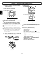
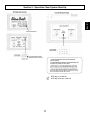
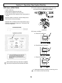
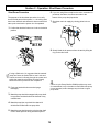
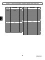
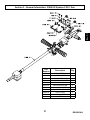
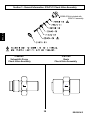
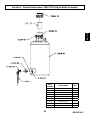
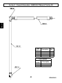
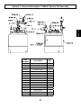
Spartan II PLC
USER MANUAL
RTM Injection System
5845 WEST 82ND STREET
INDIANAPOLIS, INDIANA
46278 U.S.A.
Phone (317) 875-5592
Fax
(317) 875-5456
Email [email protected]
Web www.glascraft.com
Table Of Contents
Section 1 Installation
1:1 Introduction ....................................................................................................................................................... 1
1:2 Standard Equipment .......................................................................................................................................... 2
1:3 System Installation ............................................................................................................................................. 3
Section 2 Operation
2:1 New System Start-up Instructions ......................................................................................................................
2:2 Shut–down Instructions ......................................................................................................................................
2:3 Operation notes ..................................................................................................................................................
2:4 Routine Care ......................................................................................................................................................
5
19
20
21
Section 3 General Information
3:1 Assembly Drawings ........................................................................................................................................... 22
3:2 Sub Assembly Drawings .................................................................................................................................... 38
Section 4 Safety Information
4:1 Operating Your Polyester System Safely ...................................................................................................... 42
...................................................................................................................................... 50
4:3 Limited Warranty Policy ............................................................................................................ 51
4:4 Technical Assistance ................................................................................................................ 52
For Your Reference ............................................................................................. INSIDE BACK COVER
4:2 Notes
Introduction
The information in this document is intended only to
indicate the components and their normal working
relationship typical use. Each assembly should be
directed by a GlasCraft distributor or made from the
GlasCraft Assembly instructions provided.
Before operating, maintaining or servicing any
GlasCraft system, read and understand all of the
technical and safety literature provided with GlasCraft
products. If you do not have the proper or related
manuals and safety literature for your GlasCraft system,
contact your GlasCraft distributor or GlasCraft,Inc.
This manual provides information for the assembly, operation, maintenance and service of this GlasCraft product as
used ina typical configuration. While it lists standard specifications and procedures, some deviations may be found.
In this GlasCraft technical and safety publication, the
following advisories will be provided where appropriate:
Is information about the procedure in progress.
In order to provide our users with the most up-to-date
technology possible, we are constantly seeking to improve
products. If technological change occurs after a product is
on the market, we will implement that technology in future
production and, if practical, make it available to current
users as a retrofit, up-date or supplement. If you find some
discrepancy between your unit and the available documentation, contact your GlasCraft distributor to resolve the
difference. GlasCraft, Inc. reserves the right to change or
modify this product as it deems necessary.
Is imperative information about equipment protection.
CAUTION
Indicates a hazardous situation which, if not avoided,
could result in minor or moderate injury.
WARNING
Careful study and continued use of this manual will provide a better understanding of the equipment and process,
resulting in more efficient operation, longer trouble-free
service and faster, easier troubleshooting.
Indicates a hazardous situation which, if not avoided,
could result in death or serious injury.
ELECTRICAL SHOCK HAZARD
Indicates a hazardous situation which, if not avoided,
could result in electrical shock or serious injury.
Sec. 1:1
Section 1 - Installation
Sec. 1:2
Section 1 - Installation
MODEL - 23280-00
Standard Equipment
Part
Number
Description
23280-00
Spartan II PLC
17440-00
Grounding Clamp Assembly
GC-1368
User Manual
3. Attach Grounding Clamp Assembly, P/N 17440-00, to
The Spartan ll PLC comes complete and fitted with all
resin hoses, catalyst bottle and filters. The injection
head is fully connected to the machine circuit and
tested and secured against leaks prior to dispatch.
System. Use a convenient Nut and Bolt to secure Lug,
P/N 13193-00, to system.
4. Securely attach Clamp, P/N 7749-00 to permanently
grounded rod or pipe.
The following instructions are to be used as a guide
for consistent and continual operation. Any deviation from the “standard operation”, usually requires
more maintenance to the equipment and material
formulation to assure consistent results. For
example: the use of fillers in resins.
Refer to specific user manuals (if available) for
detailed component start-up and shut-down instructions.
1. Select a clean, dry air supply.
It is very important to have a clean air supply.
2. Attach a 3/8” or larger air hose to the Air Inlet on the
yellow air lock-out valve. Quick disconnect fittings
should not be used because they can severely limit
air flow.
Whenever flammable or combustible liquids are transfered
from one container to another, both containers shall be
effectively bonded and grounded to dissipate static electricity.
For further information see.....
NFPA 77,Recommended Practice on Static Electricity.
5. Plug the electrical cord into a 110 outlet.
Before turning on main air:
a. check all fittings, making certain they are securely
tightened.
b. Make sure all regulators are set to zero (turn all the
way to the left).
This should be done before air or material of any kind
is introduced into the system.
Sec. 1:3
Section 1 - Installation
Sec. 1:3
Section 1 - Installation
6. Attach the green material hose
to the pick-up tube and insert the
tube into a bucket of clean solvent.
Recirculation hose from the gun.
SOLVENT
CONTAINER
SOLVENT/WASTE
CONTAINER
7. Attach the green material hose
to the material pump.
8. Insert the end of the recirculation
hose into a wast container.
Section 2 - Operation: New System Start-Up
Console Functions
EMERGENCY STOP - Shuts off operation.
(Twist red knob to reset emergency stop.
start button must be pushed to restart.)
AIR PURGE
Push Button
POWER SWITCH
AIR MOTOR
Regulator
ACCU-PRESSURE
X2 Pressure Gauge
ACCU-PRESSURE
Regulator
MAGIC BULLET
ACCU-PRESSURE
ON/OFF SWITCH
STROKE COUNTER
Reset Push Button
MOLD INJECTION
On Push Button
TOUCH SCREEN
MOLD INJECTION
Off Push Button
RECIRCULATION
ON/OFF SWITCH
SOLVENT PURGE
Push Button
Sec. 2:1
SYSTEM START BUTTON
AIR MOTOR
Pressure Gauge
Section 2 - Operation: New System Start-Up
1. Open the air valve by pushing the yellow slide
Sec. 2:1
on the valve.
2. Turn on the main power.
3. Press the start button.
Sec. 2:1
Section 2 - Operation: New System Start-Up
4. Push for set-up screen.
Section 2 - Operation: New System Start-Up
Solvent Flush Programing
9. Follow the instructions below for touch screen
operations.
Sec. 2:1
Before initial operation of any internal mix system,
make certain the solvent flush set-up is fully
operational.
Since the system is an internal mix system, the
mixer requires flushing with air-solvent-air after
each dispense Or before the mixed material starts
to gel.
5. Make sure solvent regulator is dialed to zero
(Turn knob fully counter-clockwise) and turn the
ball valve to the closed position.
6. Carefully relieve any pressure in the solvent tank by
slowly pulling the relief valve.
7. After all the pressure is released from the tank, open
the lid and fill the tank with a suitable, clean flushing
solvent and close the lid securely.
8. Turn solvent regulator clockwise to approximately
80 psi. and turn the ball valve to the open position.
10-15 seconds is recommended for air flush initial
set-up.
3-5 seconds is recommended for solvent flush initial
set-up.
Section 2 - Operation: New System Start-Up
10. Place injection nozzle over a proper waste con-
2. Before operating the material pump, flush thoroughly
tainer. Press the solvent button (located on the
front of the control panel) to assure proper flush.
Press the air flush button (located on the front of
the control panel) to purge any remaining solvent
from the gun head.
GlasCraft uses test fluid that may not be compatible
with some resins. Then, it is recommended that the
test fluid be flushed from the material pump fluid
section.
Make sure hose fittings on the pick-up hoses are tight.
3. Place the material pick-up tube into a container of
clean, suitable solvent.
11. Exhaust air through the gun head until traces of
solvent have been dissipated.
4. Place the recirculation hose into a suitable solvent/
Resin Start-UP
waste container.
1. Fill material pump lube cup with proper pump lube.
5. Turn main valve on the gun head to the recirculation
position (Towards the hoses).
Sec. 2:1
with a clean, suitable solvent to remove test fluid.
Section 2 - Operation: New System Start-Up
6. Turn the material air regulator “OFF” (counter-clock
wise).
9. The pump should cycle clean solvent through the
system and out the recirculation hose.
10. End recirculation when solvent appears reasonSec. 2:1
ably clean. “OFF”
7. Switch machine recirculation to “ON”.
11. Remove material pump pick-up tube from solvent
container and dry thoroughly.
12. Switch machine recirculation to “ON”.
8. Turn the material injection regulator slowly clockwise until gauge indicates 10 PSI or until pump
cycles slowly.
13. When solvent has stopped exiting the recirculation
hose, end recirculation. (OFF)
14. Place material pick-up tube in desired container of
material while keeping recirculation return hose in
hose in a waste container.
10
Section 2 - Operation: New System Start-Up
2. Turn the catalyst valve on the dispense gun to recir-
15. Turn machine to recirculation. (ON)
Sec. 2:1
culation position (arrow on valve should point away
from gun block).
→
16. Let material pump cycle slowly until a steady
stream of clean material is seen exiting the
recirculation hose.
17. Switch machine recirculation to “OFF”.
make sure all the air is purged out of the catalyst
pump on new start up.
3a. Pull and rotate pivot
knob to disengage the catalyst
drive arm.
b. Turn the catalyst
slave pump yellow ball
valve to the open position.
18. Secure recirculation hose in the material supply
container.
c. Hand prime the pump
until a steady stream of catalyst flows back to the bottle.
Dispose of resin in the waste container in a proper
manner.
d. Close the ball valve.
Catalyst Start-Up
1. Safely fill the catalyst supply bottle, P/N LPA-165,
(maximum two gallons) with preferred MEKP catalyst,
to a minimum level of at least two inches above the
catalyst bottle outlet fitting.
4. Set the catalyst slave pump to 3.0 percent.
For system that have PAC (Progressive Automatic
Catalyst), refer to manual injection procedures for
instructions on how to set the catalyst pump to 3%
using the touch screen.
Remove the catalyst bottle, P/N 20941-00 from catalyst
bottle bracket, P/N LPA-169 for filling. The bottle should
be placed at or below lowest level for safe filling. Never
fill the catalyst bottle while mounted in bracket as
personal injury from catalyst spillage could result.
It is usually a general practice when starting up the
system to let the system recirculate with the catalyst
slave pump set at 3.0%. This ensures good catalyst
volume movement through the system to remove air
in the catalyst system.
5. Re-engage the catalyst pivot knob. (This step is not
necessary if the system is equipt with PAC option).
11
Section 2 - Operation: New System Start-Up
Recirculation Mode Start-Up
4. Continue to cycle the machine until a steady
stream of catalyst appears out of the return tube
and is free of any air bubbles.
1. Both the catalyst valve and the material valve on the
Sec. 2:1
dispense gun should be in the recirculation position.
(Towards the hoses)
The recirculation mode should be used in initial
start-up or when air bubbles are observed coming
through the ends of the recirculation hoses.
Initial Injection Instructions
1. Turn Recirculation Switch to the OFF position.
→
2. Press manual injection (Located on Touch Screen).
2. Turn machine to recirculation. (ON)
3. (If Required), Select desired percentage of catalyst by
pushing the manual injection set-up.
3. Turn the air motor regulator slowly clockwise until
the pump cycles slowly.
12
Section 2 - Operation: New System Start-Up
6. When finished, turn catalyst & resin valves
on the gun head to recirculation position.
BEFORE FLUSHING!
THE CATALYST PUMP WILL
THEN MOVE TO THE SELECTED
POSITION.
4. Turn the material and catalyst valves to the Injection
RESIN
position.
→
CATALYST
7. Flush the gun head throughly.
a. Press the air flush button. (located on front control
panel.)
5. Depress the air switch button on the gun head to
dispense mixed material. It’s strongly recommended
at this time to do a couple of test shots in a suitable
cup to confirm proper gel time.
b. Press the solvent flush button. (located on front
control panel.)
.025 gallons per stroke
95cc per stroke
c. Press the air flush button.
8. Assure that proper catalyzation was achieved.
When making test material dispenses or during flushing
operation, make certain that dispensed material and/or
solvent is contained in a suitable container and that this
material and/or solvent is disposed of properly.
13
Sec. 2:1
When starting a new machine, it is recommended to
dispense a couple of strokes of resin into a suitable
container to ensure a proper flow of materials. This is
not required once the machine has been properly
wet-out.
Section 2 - Operation: New System Start-Up
Manual Injection Instructions
Sec. 2:1
1. Turn recirculation switch to the OFF position.
CATALYST
5. Insert port injector into mold opening.
2. Press manual injection (Located on Touch Screen).
6. Depress the air switch button trigger on gun head to
dispense mixed material.
.025 gallons per stroke
95cc per stroke
3. Select desired percentage of catalyst by pushing the
manual Injection Set-Up. Once desired catalyst
percent is selected press start to move the pump to
the selected position.
7. After the injection process turn both, catalyst valve
and material valve on the dispense gun to the
recirculation position.
RESIN
4. Turn valves on gun head to injection.
→
RESIN
14
CATALYST
Section 2 - Operation: New System Start-Up
8. Flush the gun:
If Adjustments need to be made on the timing of the
Air/ Solvent, See Flush set-up.
a. Press the air flush button. (located on front control
panel.)
c. Press the air flush button.
1. Make sure Manual Injection is NOT on.
Manual Injection Box- Blue =ON
Manual Injection Box- Gray= OFF
2. Press set-up. 1 through 6.
There are up to 30 set-up options depending on the
system.
PUSH ▲OR ▼ARROWS
TO SELECT THE ENDING
CATALYST PERCENT.
PUSH ▲OR ▼ARROWS
TO SELECT THE
STARTING CATALYST
PERCENT.
AFTER THE REQUIRED
PERCENT AND STROKES ARE
ENTERED, PRESS START TO
START THE CATALYST PUMP
POSITIONING.
RETURNS TO
SET-UP SCREEN
AND INJECTION
PROGRAMMING
PRESS
PUSHING STOP WILL STOP THE
PROGRAM. THE START BUTTON
MUST BE PUSHED AGAIN AND THE
PROGRAM WILL START OVER. TO
AVOID RESETTING THE PROGRAM
USE THE START AND STOP BUTTONS
ON THE CONSOLE AND/OR GUN
DURING THE INJECTION PROCESS.
.025 gallons per stroke
95cc per stroke
15
Sec. 2:1
b. Press the solvent flush button. (located on front
control panel.)
Automatic Injection Instructions
Section 2 - Operation: New System Start-Up
3. Secure port Injector into mold opening or use the
remote injection port.
7. Flush the system.
a. Press the air flush button.
Sec. 2:1
4. Press Start on the set-up screen.
5. Press Injection ON button.
b. Press the solvent flush button.
Injection ON will NOT function until the catalyst pump
has found the correct percentage.
c. Press the air flush button again.
After the injection sequence has been completed,
the pump will stop and the flush Indicator will flash.
If an adjustment needs to be made on the timing of
the air or solvent, refer to the flush set-up.
If additional material is required, Follow the manual
injection instructions to finish injection.
The start and stop buttons on the gun and control
panel can be pressed without changing the program.
If the stop button is pressed, the program will be
aborted and the start button must be pressed to
reset the program.
RFID Option (WRITING TAGS)
1. Select Mold scan.
2. Select Tag Write.
3. Enter password (1234) + enter / ← button
4. Select Start position % Stop position % and Total
Strokes.
.025 gallons per stroke
95cc per stroke
5. With scanner wand, scan mold chip. (Yellow light on
scanner will verify scanning).
6. Repeat steps #1, #3, and #4 for all mold chips.
7. Select Return (Tag Read)
8. Scan each chip to verify settings.
6. Turn the catalyst and resin valves on the gun to the
recirculation position before flushing.
RESIN
→
CATALYST
16
Sec. 2:1
Section 2 - Operation: New System Start-Up
RFID tag p/n: 23290-00
RFID tag carrier p/n: 23291-00
17
Section 2 - Operation: New System Start-Up
Sec. 2:1
RFID Option (READ TAGS)
5. Turn the catalyst and resin valves on the gun to the
recirculation position BEFORE FLUSHING.
1. select mold scan.
2. With scanner wand,scan mold chip.
3. Press Start (Located on Touch Screen).
4. Press Injection ON (Located on front control panel or
on gun.
RESIN
Injection ON will not function until the catalyst pump
has found the correct percentage.
Injection OFF, (Located on front control panel or gun.)
will NOT reset Injection Sequencer. The injection ON
will restart sequencer.
→
CATALYST
6. FLUSH SYSTEM:
a. Press Air Flush Button.
b. Press Solvent Flush Button.
c. Press Air Flush Button.
After Injection Sequencer has been completed,
the pump will stop and Flush indicator will flash.
If Adjustment needs to be made on the timing of the
Air or Solvent, See Flush Set-Up.
18
Section 2 - Operation: Shut Down Procedure
Shut Down Procedure
6. If you are using fillers mixed into the resin, remember on
The purpose of the shut down procedure is to verify
that all critical parts of the system, i.e., the mixing area,
have been checked and cleaned to assure trouble-free
start-up the next time the system is to be operated.
7. Shut down main air supply by closing yellow lock out
periods of shut-down, the fillers can settle to the
bottom of the pump and pipe-works.
Sec. 2:2
valve.
1. Confirm that both ball valves are in the recirculation
position.
RESIN
8. Slowly bleed the air pressure from the tank by lifting the
ring on the relief valve.
→
CATALYST
If using a filled resin it is suggested that the material
pump and hoses be flushed with a “neat” resin and
that the neat resin is flowing through the system and
exiting the material recirculation hose thoroughly
before shut down procedures are completed.
2. Flush gun head with solvent and air purge
thoroughly.
Failure to cycle Pump Shaft to DOWN position may result
in contaminants to dry or harden on shaft. When the pump
is next operated, severe damage may be done to upper
pump seals.
3. Material pump should be stopped with pump shaft
in up position and shaft should be cleaned of any
contaminants.
4. Material pump lube cup should be cleaned of
old lube and refilled with new pump lube.
5. Material pump should now be cycled so that shaft
is left in down position during shut-down period.
19
Section 2 - Operation: Operation Notes
Air or gas in the catalyst stream, leads to a different
type of fault in the molded part. This condition will be
manifest by observing when opening the mold after
injection and supposed cure, that there are wet patches
of uncured or semi-gelled resin in the molded part. The
causes attributed to this are:
Sec. 2:3
Operation Notes
Before altering catalyst percentage by moving the
catalyst pump to a new desired location on the ratio
arm ALWAYS ensure that the catalyst recirculation
valve is turned to the recirculation position, and the
air pressure is removed from the system.
1. Air is drawn in by the catalyst pump through a bad
It is absolutely essential that both streams of material
are pumped to the head without air or gas entrapped.
For example, if air is drawn into the resin stream through
the resin pump inlet system, i.e., via bad connection or
filter end coming out of resin surface, then this air if
not purged out of the machine by recirculating on bypass will naturally go to the head through the mixer and
into the RTM mold. This fault condition will manifest
itself in the molded part having very small bubbles;
almost in a froth like state, on the upper side of the
molded part once the mold is opened. The reason for
these bubbles being so small is due to the fact that air
coming through the mixer with the resin is mixed and
frothed before finally entering the mold.
connection on the inlet stream from the catalyst
container or pump inlet connection.
2. Catalyst contamination in the pump system causing
oxidation resulting in peroxide gas bubbles being
generated within the supposedly hydraulic sealed
system of the catalyst.
3. The catalyst pump has faulty seals or is
contaminated with particles.
To ensure that the catalyst system is totally hydraulically
tight, it is expedient after a period of shut-down that the procedures in the instructions for commissioning the catalyst
stream should be repeated.
20
Section 2 - Operation: Routine Care
Routine Care
It is recommended that the following service be
performed on a weekly basis.
1. Inspect and lubricate Catalyst Slave Pump Linkage.
Consult your local authorized GlasCraft distributor for
more information concerning system storage.
(See Catalyst Slave Pump User Manual.)
2. Inspect Pump Shafts on Material and Catalyst
Pumps, making certain they are clean and free of
foreign material. Clean and lubricate as required.
For long term storage of your injection system, it is
recommended that the following procedures be
followed:
1. Place dry nitrogen in the material drums and
secure drum.
2. Make certain all air and material valves are in their
“OFF” position.
21
Sec. 2:4
GlasCraft recommends that you contact your gel-coat
and/or resin supplier concerning material pot-life
during extended periods of shut-down. The decision
as to whether or not to leave material in your system
should be based on information from your material
suppliers as well as GlasCraft.
Sec. 3:1
Section 3 - General Information: 23280-00 Spartan II PLC Assembly
22
REVISION G
Sec. 3:1
Section 3 - General Information: 23280-00 Spartan II PLC Assembly
23
REVISION G
Sec. 3:1
Section 3 - General Information: 23280-00 Spartan II PLC Assembly
24
REVISION G
Sec. 3:1
Section 3 - General Information: 23280-00 Spartan II PLC Assembly
25
REVISION G
Sec. 3:1
Section 3 - General Information: 23280-00 Spartan II PLC Assembly
26
REVISION G
Part
Number
Description
Qty.
Part
Number
10773-12C
10773-14C
SCREW
6
SCREW
8
10773-28C
SCREW
Description
Qty.
23269-00
NORMALLY OPEN SENSOR
1
23269-01
NORMALLY CLOSED SENSOR
2
4
23278-00
ROLLER BEARING
1
13424-01
CABLE TIE
3
23295-00
TOUCH SCREEN CABLE
1
16028-03
HITCH PIN
1
23296-00
SERVO MOTOR CABLE
1
17440-00
GROUNDING CLAMP
1
23297-00
TERMINAL/SERVO CABLE
1
18245-02
HEAT SHRINK TUBING
1.616
23298-00
CPU/SERVO BLOCK CABLE
1
19845-00
FRP LITERATURE
1
3923-02
SPIRAL WRAP
3
19882-00
MAST CAP
1
7486-04
WASHER
4
19889-00
MOUNTING ADAPTER
2
7486-05
WASHER
16
19891-00
PIPE CLAMP
4
7486-08
WASHER
3
19892-00
COVER PLATE
8
7486-13
WASHER
3
20188-16C
SCREW
17
7733-12
HEX NUT
2
20190-30
CATALYST HOSE 30FT
2
7733-14
HEX NUT
2
20195-30
MATERIAL HOSE 3/8 ID
1
7733-17
HEX NUT
1
20368-00
SWIVEL CASTER 3 IN.
4
7733-42
HEX NUT
4
20569-00
G2 SUPPORT MAST
1
7734-06
LOCK WASHER
15
20732-01
RED TUBING 5/32 IN.
32
7734-07
LOCK WASHER
2
20732-02
BLUE TUBING 5/32 IN.
64
7734-10
LOCK WASHER
12
20732-06
GREEN TUBING 5/32 IN.
33
7734-12
LOCK WASHER
3
20864-06
SPARTAN II PUMP
1
7957-32C
SCREW
2
20941-00
CATALYST JUG
1
7957-32F
SCREW
2
2
20945-00
RECIRC. CATALYST ASSEMBLY
1
7957-48C
SCREW
21044-06
O-RING
1
7958-56C
SCREW
2
21054-01
NYLON TUBING
48
8155-160C
SCREW
8
4
21203-02
YELLOW TUBING 1/4 IN.
14
8212-20F
SCREW
21203-03
RED TUBING 1/4 IN.
14
8301-16C
SCREW
2
21203-05
GREEN TUBING 1/4 IN.
14
9704-11
P.E. TUBING
3
33
21203-12
BLUE TUBING 5/32 IN.
6
9704-83
RED P.E. TUBING
21203-13
YELLOW TUBING 5/32 IN.
32
9944-20C
SCREW
2
21203-15
ORANGE TUBING 5/32 IN.
32
9944-32C
SCREW
1
21654-02
SOLVENT TANK
1
9955-24C
SCREW
4
21663-00
MOUNTING BLOCK
1
FM-494
EXPANDABLE SLEEVING
23
21668-02
SPARTAN II PAC GUN
1
G-403
RUBBER TARP STRAP
1
21670-00
TANK SUPPORT
1
GAM-268-01
PICK-UP TUBE
1
21674-00
GUIDE HOSE
1
GC-1368
USER MANUAL
1
21694-25
MATERIAL HOSE
1
LPA-170
BOTTLE SUPPORT
1
22701-00
MX 2 BASE
1
SSP-112
SLAVE PLATE EXTENSION
1
23231-00
SPARTAN II DECAL
1
SSP-115
DRIVE ARM
1
23250-00
CONTROL BOX
1
SSP-148
RELEASE PIN
1
23251-00
MOUNTING BRACKET
3
SSP-157-01
CALIBRATION DECAL
1
23252-00
SERVO COUPLER
1
SSP-172
SURROUND GUARD
1
23253-00
SLAVE SLIDER
1
SSP-173
LEFT PUMP GUARD
1
23254-00
SSP MOUNT
1
SSP-174
GUARD ANGLE BRACKET
1
23255-00
SERVO ADAPTER PLATE
1
SSP-176
GUARD WINDOW
1
23256-00
ADJUSTMENT ROD
1
SSP-177
REAR RIGHT PUMP GUARD
1
23259-00
HEX ADAPTER
1
SSP-178
FRONT RIGHT PUMP GUARD
1
23260-00
RECISION ROD
2
SSP-190-01
SLAVE PUMP
1
23261-00
SUPPORT RAIL
2
23262-00
SERVO MOTOR
2
27
REVISION G
Sec. 3:1
Section 3 - General Information: 23280-00 Spartan II PLC Parts List
Sec. 3:1
Section 3 - General Information: 23280-00 Computer Cable Connections
28
REVISION G
Sec. 3:1
Section 3 - General Information: 23250-00 Spartan II PLC Control Box
29
REVISION E
Sec. 3:1
Section 3 - General Information: 23250-00 Spartan II PLC Control Box
30
REVISION E
Sec. 3:1
Section 3 - General Information: 23250-00 Spartan II PLC Control Box
31
REVISION E
Sec. 3:1
Section 3 - General Information: 23250-00 Spartan II PLC Control Box Parts List
Part
Number
Description
Qty.
11021-23
PIPE PLUG
2
11021-24
PIPE PLUG
2
14638-02
RIVET
6
15229-01
BREATHER VENT
15544-02
Part
Number
Description
Qty.
22238-01
POPPET VALVE
1
22249-00
AIR PURGE,ACCU-FLUSH DECAL
1
22251-00
SOLVENT FLUSH,ACCU-FLUSH DECAL
1
1
22256-00
ACTUATED TOGGLE VALVE
2
BULKHEAD FITTING
1
22263-00
“L” ADJUSTABLE FITTING
3
18199-02
AIR REGULATOR
1
22506-00
TERMINAL
15
19892-00
COVER PLATE
2
22507-00
TERMINAL END COVER
1
19916-00
PUSH SWITCH
5
23072-00
MOMENTARY,ILLUMINATED PUSH BUTTON
1
20655-04
ELBOW FITTING
9
23073-00
EMERGENCY STOP PUSH BUTTON
1
20735-01
ELBOW FITTING
4
23074-00
PUSH BUTTON COUPLING PLATE
3
20735-02
ELBOW FITTING
4
23075-01
“I” INSCRIPTION CAP
1
1
20735-03
ELBOW FITTING
1
23079-01
NORMALLY OPEN CONTACT BLOCK
20754-00
ELBOW FITTING
2
23079-02
NORMALLY CLOSE CONTACT BLOCK
2
20796-00
FITTING
9
23174-00
POWER CORD
1
1
20796-02
FITTING
6
23201-01
PANEL NUT
20796-03
FITTING
2
23201-02
PANEL NUT
2
20796-04
FITTING
3
23203-00
PILOT OPERATED REGULATOR
1
21145-00
VENT PLUG
5
23204-00
PANEL MOUNT GAUGE
2
21164-02
2AMP FUSE
4
23205-00
SELF RELIEVING PRESSURE REGULATOR
1
21203-02
YELLOW TUBING 1/4 IN.
4
23208-00
SELECTOR SWITCH
1
21203-03
RED TUBING 1/4 IN.
2
23209-00
ADAPTER VALVE
1
21203-04
BLUE TUBING 1/4 IN.
5
23210-02
TUBE REDUCER
6
21203-05
GREEN TUBING 1/4 IN.
2
23214-00
FITTING
1
21203-12
BLUE TUBING 5/32 IN.
4
23215-00
MANIFOLD
1
21203-13
YELLOW TUBING 5/32 IN.
2
23226-00
PRESSURE,MOTOR,AIR DECAL
1
21203-14
BLUE TUBING 3/8 IN.
8
23228-00
ON-OFF,ACCU-PRESSURE DECAL
1
21284-16C
SCREW
6
23229-00
ACCU-PRESSURE,X-2 DECAL
1
21287-01
HEX NUT
6
23230-00
REMOTE INJECTION PORT DECAL
1
21308-20C
SCREW
1
23232-00
PRESSURE SWITCH
4
21402-00
3-WAY VALVE
1
23233-00
NEEDLE VALVE
2
21454-00
MOUNTING BRACKET
1
23236-00
STROKE COUNTER RESET DECAL
1
21489-48C
SCREW
2
23237-00
FITTING
1
21604-01
PLASTIC TUB PLUG
3
23237-01
FITTING
1
1
21669-00
CHECK VALVE
2
23257-00
CONTROL BOX
21678-00
RECIRCULATION DECAL
1
23258-00
PLATE EXTENSION
2
21722-00
MOUNTING BRACKET
1
23263-00
SMARTSTEP DRIVE
1
21823-00
DIN RAIL
2.208
23264-00
TERMINAL BLOCK
1
21861-00
CONDUCTOR CONNECTOR
1
23265-00
POWER SUPPLY
1
21889-00
FUSEHOLDER
4
23266-00
CPU
1
22104-00
EMERGENCY STOP DECAL
1
23267-00
PLC
1
22117-00
TERMINAL BLOCK JUMPER
1
23268-00
OUTPUT RELAY
1
22171-01
SWITCH BLOCK
1
23270-00
POWERSUPPLY
1
22174-01
SWITCH BLOCK COVER
1
23271-00
TOUCHSCREEN
1
22178-00
ON/OFF SWITCH
1
23272-00
SELECTOR SWITCH
1
22212-01
BULKHEAD FITTING
1
23273-00
SELECTOR KNOB
1
22212-02
BULKHEAD FITTING
4
23274-00
STATION MANIFOLD
1
22218-00
PUSH-ON HOSE FITTING
2
23275-00
SOLENOID VALVE
1
22222-00
INJ EMERGENCY,ACCU-SHOT DECAL
1
23276-00
SOLENOID VALVE
3
32
REVISION E
Part
Number
Description
Qty.
23277-00
SOLENOID VALVE
1
23279-00
RUBBER SEAL
1
23281-00
NYLON BRACKET
1
23282-00
SPARTAN II PAC DECAL
1
23287-00
AIR FILTER
1
23287-01
AIR FILTER
1
3800-08
COPPER WIRE #18 BLACK
4342-01
ELBOW FITTING
3
4342-04
ELBOW FITTING
1
5307-01
CONDUIT NUT
2
5754-01
SPADE SOCKET TERMINAL LUG
2
5754-05
SPADE SOCKET TERMINAL LUG
6
6782-03
FITTING
1
7315-05
RUBBER GROMMET
1
7315-06
RUBBER GROMMET
3
7486-03
WASHER
2
7486-05
FENDER WASHER
2
7486-28
WASHER
6
7597-06
SWIVEL FITTING
1
7733-04
HEX NUT
2
7733-06
HEX NUT
5
7733-07
HEX NUT
6
7733-12
HEX NUT
1
7734-01
LOCK WASHER
6
7734-02
LOCK WASHER
2
7734-03
LOCK WASHER
7
7734-04
LOCK WASHER
6
7734-06
LOCK WASHER
3
7734-10
LOCK WASHER
4
7735-16C
SCREW
4
7750-02
COPPER WIRE #14 BLACK
7966-03
FITTING
1
8115-02
FITTING
1
8115-03
FITTING
1
8115-04
FITTING
1
8155-40C
SCREW
4
8212-48F
SCREW
2
8301-96C
SCREW
3
9672-16
NIPPLE FITTING
1
9943-16F
SCREW
4
9944-20C
SCREW
2
ISD-141-3
MINI REGULATOR
1
MPB-208
AIR FILTER
1
RM-856-05
ELBOW FITTING
1
RS-141-01
CORD GRIP
1
RS-141-02
CORD GRIP
1
33
Sec. 3:1
Section 3 - General Information: 23250-00 Spartan II PLC Control Box Parts List
REVISION E
Sec. 3:1
Section 3 - General Information: 23250-00 Spartan II PLC Control Box Schematic
34
REVISION E
Sec. 3:1
Section 3 - General Information: 21668-01 Spartan II Gun Assembly
23547-01
Check Valve Assembly
Accu-Pressure Valve
35
REVISION E
Sec. 3:1
Section 3 - General Information: 21668-01 Spartan II Gun Parts List
Part
Number
Description
Qty.
Part
Number
Description
Qty.
RM-856-04
ELBOW FITTING
1
21667-00
BALL VALVE
1
13076-32
O-RING
1
21675-00
CHECK VALVE
2
13867-61
O-RING
1
21676-00
CRUSH WASHER
2
13867-62
O-RING
1
22904-00
CHECK VALVE STEM
1
13867-63
O-RING
1
22906-00
CRUSH WASHER
1
15902-00
FITTING
1
22908-00
NUT
1
19881-00
FITTING
1
22909-00
CHECK VALVE BODY
1
20306-00
ELBOW FITTING
1
23216-00
MPS BLOCK
1
20735-04
ELBOW FITTING
1
23217-00
PRESSURE SENSOR PISTON
1
20796-02
FITTING
1
23218-00
BOTTOM PLATE
1
20796-03
FITTING
1
23219-00
TOP PLATE
1
20810-00
BALL VALVE
1
23221-00
GASKET
1
20878-00
VALVE
1
23223-00
INJECTION PORT
1
20879-00
PUSH BUTTON
1
23524-01
SPRING
1
21044-02
O-RING
1
23540-00
CHECK VALVE BODY
1
21454-00
MOUNTING BRACKET
1
7597-04
SWIVEL FITTING
1
21465-32C
STUD
2
7734-04
LOCK WASHER
2
21535-00
CHECK VALVE
1
7966-17
FITTING
1
21656-00
GUN BLOCK
2
8114-03
ELBOW FITTING
1
21662-00
INJECTION WAND
1
8212-16C
SCREW
2
21664-00
CHECK VALVE
1
8462-17
FITTING
1
21665-00
GUN HANDLE
2
8560-03
FITTING
1
8560-22
FITTING
1
9944-48C
SCREW
4
36
REVISION E
Sec. 3:1
Section 3 - General Information: 21668-02 Spartan II PLC Gun
Part
Number
Description
Qty.
20735-04
ELBOW FITTING
3
20796-02
CONNECTOR FITTING
2
20878-00
MINIATURE VALVE
2
21454-00
MOUNTING BRACKET
2
21668-01
SPARTAN II GUN
1
22213-01
RED PUSH BUTTON
1
22213-02
BLACK PUSH BUTTON
1
22223-90
PUSH BUTTON BRACKET
1
22224-00
TEE FITTING
1
7734-04
LOCK WASHER
6
8212-16C
SCREW
6
37
REVISION A
Section 3 - General Information: 23547-01 Check Valve Assembly
Sec. 3:2
22909-00 Not included with
23547-01 assembly
21664-00
Solvent/Air Purge
Check Valve Assembly
21675-00
Resin
Check Valve Assembly
38
REVISION E
Sec. 3:2
Section 3 - General Information: 20941-00 Catalyst Bottle Assembly
39
Part
Number
Description
Qty.
LPA-172
BOTTLE SUPPLY FILTER
1
20390-00
FITTING
1
20934-00
JUG CAP
1
20939-00
MALE CONNECTOR
2
20940-00
SUPPLY BOTTLE
1
21039-00
FITTING
1
21040-00
ELBOW FITTING
1
21045-01
HEX NUT
1
9704-11
TUBING
5
REVISION G
Sec. 3:2
Section 3 - General Information: GAM-268-01 Material Pick-Up Kit
Part
Number
Description
Qty.
20394-00
PICK-UP TUBE
1
20395-00
ELBOW FITTING
1
20397-01
MESH FILTER
1
20398-02
MATERIAL HOSE
1
Filter Options
40
Part
Number
Description
20397-02
100 MESH
20397-03
50 MESH
REVISION D
Sec. 3:2
Section 3 - General Information: 21654-01 Solvent Pot Assembly
Part
Number
Description
Qty.
11021-23
PIPE PLUG
1
20324-00
SOLVENT TANK
1
20365-00
RELIEF VALVE
1
20655-02
ELBOW FITTING
1
20720-00
PRESSURE RELIEF VALVE
1
20796-00
FITTING
1
21669-00
CHECK VALVE
1
22253-01
BALL VALVE
1
22254-01
ELBOW FITTING
1
22256-00
TOGGLE VALVE
1
23283-00
TANK WARNING DECAL
1
4342-01
ELBOW FITTING
1
6782-01
TEE FITTING
1
7892-03
FITTING
1
8115-04
NIPPLE FITTING
1
ISD-141-3
MINI REGULATOR
1
ISD-142
GAUGE
1
41
Section 4 - Safety Information
Operating Your Polyester System
Safely
particularly Paragraph (m) Organic Peroxides
and Dual Component Coatings.
Other standards and recognized authorities to consult are the National Fire Protection Association
(NFPA) bulletins as follows:
1.0 Introduction
Sec. 4:1
Any tool, if used improperly, can be dangerous.
Safety is ultimately the responsibility of those using
the tool. In like manner, safe operation of polyester processes is the responsibility of those who use
such processes and those who operate the equipment. This manual outlines procedures to be followed in conducting polyester operations safely.
• NFPA No. 33 Chapter 14, Organic Perox
ides and Dual Component Materials
• NFPA No. 63 Dust Explosion Prevention
• NFPA No. 70 National Electrical Code
• NFPA No. 77 Static Electricity
• NFPA No. 91 Blower and Exhaust System
• NFPA No. 654 Plastics Industry Dust
Hazards
• Type of Fire Extinguishing equipment
recommended :
This system has been specifically designed for use
of Polyester Resin ,Gel-Coat ,and Methyl Ethyl Ketone Peroxides (MEKP) applications. Other formulations or blends considered for use in this equipment is strictly prohibited without the expressed
consent by GlasCraft Inc.
Fire Extinguisher -- code ABC ,rating number
4a60bc. Extinguishing Media -- Foam, Carbon Dioxide, Dry Chemical, Water Fog.
GlasCraft, Inc. cannot eliminate every danger nor
foresee every circumstance that might cause an injury during equipment operation. Some risks, such
as the high pressure liquid stream that exits the
spray tip, are inherent to the nature of the machine
operation and are necessary to the process in order to manufacture the end-product. For this reason, ALL personnel involved in polyester operations
should read and understand the Safety Manual. It is
very important for the safety of employees involved
in the operation that equipment operators, maintenance and supervisory personnel understand the
requirements for safe operation.
Copies of the above bulletins are available, at a
nominal charge from:
Research Report No. 11 of the American Insurance
Association deals with “Fire, Explosion and Health
Hazards of Organic Peroxides”. It is published by...
Each user should examine his own operation, develop his own safety program and be assured that
his equipment operators follow correct procedures.
GlasCraft hopes that this manual is helpful to the
American Insurance Association
85 John Street
New York, New York 10038
Local codes and authorities also have standards to
be followed in the operation of your spraying equipment. Your insurance carrier will be helpful in answering questions that arise in your development of
safe procedures.
user and recommends that the precautions in this
manual be included in any such program. GlasCraft
recommends this Safety Manual remain on your
equipment at all times for your personnel safety.
1.2 Personnel Safety Equipment
In addition to the manual, GlasCraft recommends
that the user consult the regulations established under the Occupational Safety & Health Act (OSHA),
particularly the following sections:
•
•
•
National Fire Protection Association
470 Atlantic Avenue
Boston, MA 02210
GlasCraft recommends the following Personal
Safety Equipment for conducting safe operations of
the Polyester Systems:
1910.94 Pertaining to ventilation.
1910.106 Pertaining to flammable liquids.
1910.107 Pertaining to spray finishing
operations,
42
Section 4 - Safety Information
2.0Material Safety
2.1 Hazards Associated with
Laminating Operations
The major hazards which should be guarded against in
polyester laminating operations are those associated
with:
1. The flammability and explosion dangers of the
catalyst normally used - Methyl Ethyl Ketone
Peroxide (MEKP).
2. The flammability dangers of clean-up solvents
sometimes used (GlasCraft recommends that
clean-up solvents be nonflammable), and of resin
diluents used, such as styrene.
3. The flammability dangers of catalyst diluents, if
used. (GlasCraft recommends that catalyst not
be diluted.)
4. The flammability dangers of the uncured
liquid resins used.
5. The combustibility dangers of the cured laminate,
accumulations of overspray, and laminate
sandings.
6. The toxicity dangers of all the chemicals used in
laminating operations with respect to ingestion,
inhalation and skin and eye hazards.
2.2
Catalyst
(Methyl Ethyl Ketone Peroxide)
MEKP is among the more hazardous materials found
in commercial channels. The safe handling of the
“unstable (reactive)” chemicals presents a definite
challenge to the plastics industry. the highly reactive
property which makes MEKP valuable to the plastics
industry in producing the curing reaction of polyester
resins also produces the hazards which require
great care and caution in its storage, transportation,
handling, processing and disposal.
Contamination with promoters, or materials containing
promoters, such as laminate sandings, or with any
readily oxidizable material, such as brass or iron,
will cause exothermic “redox” reactions which can
become explosive in nature.
Heat applied to MEKP, or heat build-up from
contamination reactions can cause it to reach
what is called its Self-Accelerating Decomposition
Temperature (SADT).
Researchers have reported measuring pressure ratesof-rise well in excess of 100,000 psi per second when
certain MEKP’s reach their SADT. (For comparison, the
highest pressure rate-of-rise listed in NFPA Bulletin No.
68, “Explosion Venting”, is 12,000 psi per second for an
explosion of 12% acetylene and air. The maximum value
listed for a hydrogen explosion is 10,000 psi per second.)
Some forms of MEKP, if allowed to reach their SADT, will
burst even an open topped container. This suggests that
it is not possible to design a relief valve to vent this order
of magnitude of pressure rate-of-rise. The user should be
aware that any closed container, be it a pressure vessel,
surge chamber, or pressure accumulator, could explode
under certain conditions. There is no engineering substitute
for care by the user in handling organic peroxide catalysts.
If, at any time, the pressure relieve valve on top of the
catalyst tank should vent, the area should be evacuated at
once and the fire department called. The venting could be
the first indication of a heat, and therefore, pressure buildup that could eventually lead to an explosion. Moreover,
if a catalyst tank is sufficiently full when the pressure
relief valve vents, some catalyst may spray out, which
could cause eye injury. For this reason, and many others,
anyone whose job puts them in an area where this vented
spray might go, should always wear full eye protection
even when laminating operations are not taking place.
43
Sec. 4:1
GlasCraft recommends that the user consult the state
and local regulations established for all Safety equipment listed.
MEKP is not a single chemical. Various polymeric forms
may exist which are more or less hazardous with respect
to each other. These differences may arise not only
from different molecular structures (all are, nevertheless,
called “MEKP”) and from possible trace impurities left
from the manufacture of the chemicals, but may also
arise by contamination of the MEKP with other materials
in its storage or use.Even a small amount of
contamination with acetone, for instance, may produce
an extremely shock-sensitive and explosive compound.
Section 4 - Safety Information
Safety in handling MEKP depends to a great extent on
employee education, proper safety instructions and safe
use of the chemicals and equipment. Workers should
be thoroughly informed of the hazards that may result
from improper handling of MEKP, especially in regards
to contamination, heat, friction and impact. They should
be thoroughly instructed regarding the proper action
to be taken in the storage, use and disposal of MEKP
and other hazardous materials used in the laminating
operation.
In addition, users should make every effort to:
1. Store MEKP in a cool, dry place in original
containers away from direct sunlight and away
from other chemicals.
Sec. 4:1
2. Keep MEKP away from heat, sparks and open
flames.
3. Prevent contamination of MEKP with other
materials, including polyester overspray and
sandings, polymerization accelerators and
promoters, brass, aluminum and nonstainless steels.
4. Never add MEKP to anything that is hot, since explosive decomposition may result.
5. Avoid contact with skin, eyes and clothing.
Protective equipment should be worn at all
times. During clean-up of spilled MEKP,
personal safety equipment, gloves and eye
protection must be worn. Fire fighting
equipment should be at hand and ready.
with copious quantities of clean water and
disposed of in accordance with the catalyst
manufacturer’s instructions.
The extent to which the user is successful in
accomplishing these ends and any additional recommendations by the catalyst manufacturer determines
largely the safety that will be present in his operation.
2.3 Clean-Up Solvents and Resin
Diluents
A hazardous situation may be present in your pressurized fluid system!
Hydrocarbon Solvents can cause an explosion when
used with aluminum or galvanized components in a
closed (pressurized) fluid system (pumps, heaters, filters, valves, spray guns, tanks, etc.)
The explosion could cause serious injury, death and/or
substantial property damage.
Cleaning agents, coatings, paints, etc. may contain
Halogenated Hydrocarbon Solvents.
Some GlasCraft spray equipment includes aluminum or
galvanized components and will be affected by
Halogenated Hydrocarbon Solvents.
There are three key elements to the Halogenated
Hydrocarbon (HHC) solvent hazard.
6. Avoid spillage, which can heat up to the point of self-ignition.
1. The presence of HHC solvents. 1,1,1Trichloroethane and Methylene Chloride are the
most common of these solvents. However, other
HHC solvents are suspect if used; either as part
of paint or adhesives formulation, or for clean-up
flushing.
7. Repair any leaks discovered in the catalyst
system immediately, and clean up the leaked
catalyst at once in accordance with the
catalyst manufacturer’s instructions.
2. Aluminum or Galvanized Parts. Most handling
equipment contains these elements. In contact
with these metals, HHC solvents could generate
a corrosive reaction of a catalytic nature.
8. Use only original equipment or equivalent parts
from GlasCraft in the catalyst system
(i.e.: hoses, fittings, etc.) because a dangerous chemical reaction may result between
substituted parts and MEKP.
3. Equipment capable of withstanding pressure.
When HHC solvents contact aluminum or galva
nized parts inside a closed container such as a
pump, spray gun, or fluid handling system, the
chemical reaction can, over time, result in
a build-up of heat and pressure, which can reach
explosive proportions. When all three elements
are present, the result can be an extremely
violent explosion. the reaction can be sustained
with very little aluminum or galvanized metal; any
amount of aluminum is too much.
9. Catalyst accumulated from the purging of
hoses or the measurement of fluid output
deliveries should never be returned to the
supply tank. such catalyst should be diluted
44
Section 4 - Safety Information
materials or solvents, such as MEK, alcohol, and toluene, may render the inhibitors ineffective.
The use of reclaimed solvents is particularly hazardous.
Reclaimers may not add any inhibitors. Also, the possible presence of water in reclaimed solvents could feed
the reaction.
Anodized or other oxide coatings cannot be relied upon
to prevent the explosive reaction. Such coatings can
be worn, cracked, scratched, or too thin to prevent contact. There is no known way to make oxide coatings or
to employ aluminum alloys which will safely prevent the
chemical reaction under all circumstances.
Several solvent suppliers have recently begun promoting
HHC solvents for use in coating systems. The increasing
use of HHC solvents is increasing the risk. Because of
their exemption from many State Implementation Plans
as Volatile Organic Compounds (VOC’s), their low flammability hazard, and their not being classified as toxic or
carcinogenic substances, HHC solvents are very desirable in many respects.
Do not use Halogenated Hydrocarbon solvents in pressurized fluid systems having aluminum or galvanized
wetted parts.
GlasCraft recommends that you contact your solvent
supplier regarding the best non-flammable clean-up solvent
with the heat toxicity for your application.
If, however, you find it necessary to use flammable solvents,
they must be kept in approved, electrically grounded containers.
Bulk solvent should be stored in a well-ventilated,
separate building, 50 feet away from your main plant.
You should allow only enough solvent for one day’s use in
your laminating area.
“NO SMOKING” signs must be posted and observed in all
areas of storage or where solvents and other flammable materials are used.
Adequate ventilation (as covered in OSHA Section 1910.94
and NFPA No. 91) is important wherever solvents are stored
or used, to minimize, confine and exhaust the solvent vapors. Solvents should be handled in accordance with OSHA
Section 1910.106 and 1910.107.
2.4 Catalyst Diluents
GlasCraft spray-up and gel-coat systems currently produced
are designed so that catalyst diluents are not required.
GlasCraft, therefore, recommends that diluents not be used.
This avoids the possible contamination which could lead to
an explosion due to the handling and mixing of MEKP and
diluent. In addition, it eliminates any problems from the diluent being contaminated through rust particles in drums,
poor quality control on the part of the diluent supplier, or any
other reason. If, however, diluents are absolutely required,
contact your catalyst supplier and follow his instructions explicitly. Preferably, the supplier should premix the catalyst to
prevent possible “on the job” contamination while mixing.
GlasCraft is aware of NO stabilizers available to
prevent Halogenated Hydrocarbon solvents from
reaction under all conditions with aluminum components
in a closed fluid system.
TAKE IMMEDIATE ACTION...
Halogenated Hydrocarbon solvents are dangerous
when used with aluminum components in a closed fluid
system.
If diluents are not used, it should be remembered that catalyst spillage, gun, hose and packing leaks are potentially
more hazardous, since each drop contains a higher concentration of catalyst, and therefore will react quicker with overspray and the like.
Consult your material supplier to determine whether
your solvent or coating contains Halogenated Hydrocarbon Solvents.
Resin should be stored in a well ventilated building
at least 50 feet from your main plant. In addition, the
storage temperature should not exceed 75 degrees F.
45
2.5 Uncured Liquid Resin
Sec. 4:1
The reaction is unpredictable. Prior use of an HHC solvent without incident (corrosion or explosion) does NOT
mean that such use is safe. These solvents can be dangerous alone (as a clean-up or flushing agent) or when
used as a component or a coating material. There is no
known inhibitor that is effective under all circumstances.
Furthermore, the mixing of HHC solvents with other
Section 4 - Safety Information
In your main plant, store only enough resin for one day’s
production.
“NO SMOKING” signs must be posted and observed in
all areas where resin is stored and/or used.
Refer to OSHA Section 1910.94, 1910.106, 1910.107
and consult resin suppliers for more detailed information.
Adequate ventilation (as covered in OSHA Section
1910.94 and NFPA No. 91) is important wherever solvents are stored or used, to minimize, confine and exhaust the solvent vapors.
Sec. 4:1
Resin must never be stored in an area where MEKP is
stored or used.
Open-top drums should not be used, due to possible
contamination and possible catalyzation from overspray
or spillage of MEKP into drum, which could not only severely damage the polyester spray system, but might
also cause the drum of resin to ignite.
When spraying test patterns or purging the gun, always
remove the test samples and waste from the building immediately and dispose of them in accordance with your
material supplier’s recommendations.
2.6 Cured Laminate, Overspray and
Laminate Sandings Accumulation
Remove all accumulations of overspray, FRP sandings,
etc. from the building as they occur. If this waste is allowed to build up, spillage of catalyst is more likely to
start a fire, In addition, the fire would burn hotter and
longer.
3. Inspect resin and catalyst hoses daily for wear or
stress at the entry and exits of the boom sections
and at the gun and fittings. Replace if wear or
weakness is evident or suspected.
4. Arrange the hoses and fiberglass roving guides
so that the fiberglass strands DO NOT rub
against any of the hoses at any point. If allowed
to rub, the hoses may be cut through, causing a
hazardous leakage of material which could increase the danger of fire. Also the material may
spew onto personnel in the area.
2.7 Toxicity of Chemicals
GlasCraft recommends that you consult OSHA Sections
1910.94, 1910.106, 1910.107 and NFPA No. 33, Chapter
14, and NFPA No. 91.
Contact your chemical supplier(s) and determine the toxicity
of the various chemicals used, as well as the best methods
to prevent injury, irritation and danger to personnel.
Also determine the best methods of first aid treatment for
each chemical used in your plant.
2.8 Treatment of Chemical Injuries
Great care should be used in handling the chemicals (resins, catalyst and solvents) used in polyester systems. Such
chemicals should be treated as if they hurt your skin and
eyes and as if they are poison to your body. For this reason,
GlasCraft recommends the use of protective clothing and
eye wear in using polyester systems.
However, users should be prepared in the event of such an
injury. Precautions include:
Floor coverings, if used, should be non-combustible.
Spilled or leaked catalyst may cause a fire if it comes in
contact with an FRP product, oversprayed chop or resin,
FRP sandings or any other material with MEKP.
To prevent this spillage and leakage, you should:
1. Maintain your GlasCraft System. Check the gun
several times daily for catalyst and resin packing
or valve leaks. REPAIR ALL LEAKS
IMMEDIATELY.
2. Never leave the gun hanging over, or lying inside
the mold. A catalyst leak in this situation would
certainly damage the part, possible the mold, and
46
may cause a fire.
1. Know precisely what chemicals you are using and
obtain information from your chemical supplier on
what to do in the event the chemical gets
onto your skin or into the eyes, or is swallowed.
2. Keep this information together and easily available
so that it may be used by those administering first
aid or treating the injured person.
3. Be sure the information from your chemical
supplier includes instructions on how to treat
any toxic effects the chemicals may have.
Section 4 - Safety Information
3.1 Emergency Stop Procedures
The following steps should be followed in order to stop the
machinery in an emergency situation:
1. The yellow air valve located where the air
enters the machine should be pushed to
the “OFF” (closed) position. To do this simply
push on the lever protruding out the side of
the valve. This will also cause all the system
air to bleed out of the system in a matter of a
few seconds thus making the system
incapable of operating.
Fast treatment of the outer skin and eyes that contact
such chemicals generally includes immediate and thorough washing of the exposed skin and immediate and
continuous flushing of the eyes with lots of clean water
for at least 15 minutes or more. These general instructions of first aid treatment, however, may be incorrect for
some chemicals; that is why you must know the chemicals and treatment before an accident occurs. Treatment
for swallowing a chemical frequently depends upon the
nature of the chemical.
Step 2 is a precautionary step and should be followed
whenever the emergency stop valve is activated to the
stop mode. Failure to do so will damage regulators
and components when reactivating to the ON position.
Refer to your System User Manual for complete
and detailed operating instructions and service
information.
2. Turn all system regulators to OFF (counterclockwise) position.
Verify that the Catalyst Pressure Relief Line and the
Resin Return Line are secured before relieving catalyst
and resin fluid pressure.
3.0 Equipment Safety
3. Catalyst pressure in the Slave Pump can be
eliminated by rotating the yellow valve handle
on the Slave Pump 90 degrees to the “ON”
position.
GlasCraft suggest that personnel safety equipment such
as EYE GOGGLES, GLOVES, EAR PROTECTION, and
RESPIRATORS be worn when servicing or operating this
equipment. Ear protection should be worn when operating a fiberglass chopper to protect against hearing loss
since noise levels can be as high as 116 dB (decibels).
This equipment should only be operated or serviced by
technically trained personnel!!!
The “ON” position the valve handle is parallel (in line)
with the valve body .
The “OFF” position the valve handle is perpendicular
(across) the valve body.
4. Resin pressure can be eliminated by rotating
the yellow handled valve on the bottom of
the fluid filter 90 degrees. Place a container
under the bottom of the valve to catch any
resin that is ejected from the valve.
Never place fingers, hands, or any body part near or directly in front of the spray gun fluid tip. The force of the
liquid as it exits the spray tip can cause serious injury
by shooting liquid through the skin. NEVER LOOK DIRECTLY INTO THE GUN SPRAY TIP
OR POINT THE GUN AT OR NEAR ANOTHER PERSON.
(TREAT THE GUN AS IF IT WERE A LOADED PISTOL)
47
Sec. 4:1
Contact a doctor immediately in the event of any injury
and give him the information you have collected. If your
information includes first aid instructions, administer first
aid immediately while you are contacting the doctor.
Section 4 - Safety Information
3.2 General Safety Precautions
•
Do not operate Fiberglass Chopper Guns with
out protective covers in place.
• Correct packing or valve seat leaks immediately.
• Never immerse the gun in any liquid.
• Periodically check operation of catalyst alarms
to make sure they are operation properly.
• Frequently check condition of hoses. Replace worn
hoses and other parts before they fail.
• Catalyst fluid nozzles and seals MUST be in good
condition at all times to prevent internal and
external leaks. Inspect periodically and replace
as needed, or at intervals of three to four months.
Use catalyst nozzle seal only once to prevent
possible leakage of catalyst into air passages
of gun.
• Make absolutely certain that all pressure has been
relieved from the gun before disassembly from the
hoses before loosening any fittings; from the
material or catalyst pump before disassembly; from
the catalyst injector before disassembly or filling.
• If you have any doubt that fluid pressure is relieved,
call your GlasCraft distributor or GlasCraft, Inc.
before proceeding with any disassembly.
• Use only genuine GlasCraft replacement parts when
repairing your system. Substitutes may not be the
proper material or may not fit the system and may
cause dangerous operating conditions and the
failure of other components.
The following general safety precautions should be followed when servicing or operating this equip
ment to ensure operator safety:
•
•
Sec. 4:1
•
•
•
•
•
•
•
When filling catalyst container, protective eye
equipment must be worn to protect against
injuries.
Always maintain adequate material levels to
prevent loss of prime during system operation.
At the first sign of a leak, stop operations, activate emergency stop valve, back off air regulators and open all bleed valves to remove
all pressure from the gun, hoses, pump, catalyst
system and any other liquid containers.
Solvent Pot Pressure Relief:
Turn Solvent Pressure Regulator counter clock
wise (ccw) until regulator handle stops.
Open Petcock valve to bleed Solvent Tank
pressure completely.
Catalyst Injector Pressure Relief:
Refer to Catalyst Injector User Manual for
proper pressure relief.
Never operate a Fiberglass System with
fixed Pinch Point guards removed from system.
48
Section 4 - Safety Information
Never use hard materials such as wire, pins, etc., To
clear a plugged gun. Hard materials can cause permanent damage. Dab with a bristle brush, blow backwards with air until clear while wearing a protective
eye shield. Repeat as many times as necessary.
Do not perform any maintenance or repairs until you
have followed the precautions stated above. If you,
as an equipment operator or supervisor, do not feel
that you have been adequately trained or instructed
and that you lack the technical knowledge to operate
or perform maintenance on a piece of glascraft equipment, please call glascraft, inc. Before operating or
performing maintenance on the equipment.
3.3 Grounding
Grounding an object means providing an adequate
path for the flow of an electrical charge from the object to the ground. An adequate path is one that permits charge to flow from the object fast enough that
it will not accumulate to the extent that a spark can
be formed. It is not possible to define exactly what
will be an adequate path under all conditions since it
depends on many variables.
In any event, the grounding means should have
the lowest possible electrical resistance. Grounding
straps should be installed on all loose conductive
objects in the spraying area. This includes material
containers and equipment. GlasCraft recommends
grounding straps be made of AWG No. 18 stranded
wire as a minimum, and that larger wire be used
where possible. NFPA Bulletin No. 77 states that the
electrical resistance of such a leakage path may be
as low as 1 meg ohm (106 ohms) but that resistances
as high as 10,000 meg ohms will produce an adequate leakage path in some cases.
All statements, information and data given herein
are believed to be accurate and reliable but are presented without guaranty, warranty or responsibility
of any kind expressed or implied. The user should
not assume that all safety measures are indicated
or that other measures are not required.
Whenever flammable or combustible liquids are
transferred from one container to another, or from
one container to the equipment, both containers or
container and equipment shall be effectively bonded
and grounded to dissipate static electricity.
For further information, see National Fire Protection Association (NFPA) 77 titled “Recommended
Practice on Static Electrical”. Refer especially to Section 7-7 titled “Spray Application of Flammable and
Combustible Materials”. Check with local codes and
authorities for other specific standards that might apply to your application.
5845 WEST 82nd STREET, SUITE 102
INDIANAPOLIS, INDIANA 46728 U.S.A.
PHONE (317) 875-5592
FAX (317) 875-5456
GlasCraft provides a grounding wire and clamp
assembly p/n 17440-00 with all FRP equipment.
49
Sec. 4:1
If you have any questions regarding the above precautions or any service or operation procedures, call
your glascraft distributor or glascraft, inc.
Sec. 4:2
Notes
50
Limited Warranty Policy
GLASCRAFT, INC. (“GlasCraft”) warrants to the original Purchaser of GlasCraft manufactured equipment
and parts, that all GlasCraft manufactured equipment and parts will conform to their published written specifications and
be free of defects in workmanship and material for a period of one (1) year from the original date of installation. GlasCraft
makes no warranty to anyone other than the original Purchaser.
If any GlasCraft manufactured part or equipment is found to be defective in workmanship or material within the one-year
period from the date of installation, as determined solely by GlasCraft, GlasCraft, in its sole discretion, will either repair
or replace the defective part or equipment at GlasCraft’s cost, including freight charges both ways, or credit or refund the
purchase price for the defective equipment or part.
A warranty claim will be honored only when:
1. GlasCraft has been informed, in writing, of any such defect in workmanship or material within ten (10) days
after discovery by the original Purchaser;
3. The claimed defective equipment or part has been returned to GlasCraft by the original Purchaser, freight
prepaid (with proper return authorization number(s) attached), to: GlasCraft, Inc., 5845 West 82nd Street,
Suite 102, Indianapolis, IN 46278, U.S.A.
This warranty shall not apply to any equipment or parts that have been altered or repaired by anyone other than GlasCraft
or to defects or damage resulting from improper installation, misuse, negligence, accident, or use not specified by
GlasCraft. This warranty shall not apply to any equipment where any parts or components were replaced by any parts
or components not manufactured or supplied by GlasCraft. The decision by GlasCraft shall be conclusive and binding
on Purchaser.
GlasCraft does not warrant that any equipment or parts sold to Purchaser meet or comply with any local, state, federal,
or other jurisdiction’s regulations or codes. GlasCraft does not warrant that any equipment or part sold to Purchaser,
when used individually or in concert with any other part, equipment, device, component or process, does not infringe on
any patent rights of any third party. GlasCraft only warrants that it has no specific knowledge of any such infringement.
GlasCraft makes no warranty as to any parts or equipment manufactured by others. Purchaser shall look solely and
only to the manufacturer of such parts or equipment with respect to any warranty claims. GlasCraft hereby assigns to
Purchaser the original manufacturer’s warranties to all such equipment and parts, to the full extent permitted.
THE AFORESAID WARRANTY IS IN LIEU OF ALL OTHER WARRANTIES, EXPRESS OR IMPLIED. SPECIFICALLY THERE ARE NO WARRANTIES OF MERCHANTABILITY OR FITNESS
FOR A PARTICULAR PURPOSE, WHICH WARRANTIES ARE SPECIFICALLY DISCLAIMED.
GlasCraft shall not be liable for any loss or expense resulting from damage or accidents caused by improper use or application of materials manufactured or sold by GlasCraft or its distributors or agents.
UNDER NO CIRCUMSTANCES SHALL GLASCRAFT’S LIABILITY EXCEED THE AMOUNT PURCHASER PAID FOR THE CLAIMED DEFECTIVE EQUIPMENT OR PART. UNDER NO CIRCUMSTANCES SHALL GLASCRAFT BE LIABLE FOR INCIDENTAL OR CONSEQUENTIAL DAMAGES OR FOR LOST PROFITS.
No action arising from or relating to any goods manufactured by or purchased from GlasCraft may be brought more than
one (1) year after the cause of action accrues.
51
Sec. 4:3
2. An official of GlasCraft has issued a return authorization number; and
Technical Assistance............
Thank You for selecting GlasCraft spray equipment
Should you have any questions or need technical assistance, contact your factory authorized
GlasCraft distributor.
Distributor: _________________________
Phone: ____________________________
Contact: ___________________________
Sec. 4:3
phone 1.bmp
For any issues your distributor cannot address, the GlasCraft technical service department is
always available to assist you with the operation of your spray equipment. To help our technical
representatives expedite your call and better address your questions, please have the following
information ready and available when you phone GlasCraft.
* If your questions are not urgent, You can e-mail all correspondence to [email protected]
Model: _____________________________
Air compressor size: __________________
Compressor to system supply line: _______
Spray gun: __________________________
Serial number: _______________________
Pressure at the system: _______________
Material pump: _______________________
Serial number: _______________________
Main air line volume: __________________
System gauge pressures
Catalyst pump: _______________________
AAC pressure: _____________________
Chopper: ____________________________
Serial number: _______________________
Atomizing air pressure: ________________
(external mix)
Type of material: ______________________
Material pump pressure: _______________
Type of catalyst: ______________________
Solvent flush pressure: ________________
Catalyst percentage: __________________
52
For Your Reference
Date Purchased
__________________________________________________
Distributor
______________________________________________________
______________________________________________________
Contact
______________________________________________________
Phone
______________________________________________________
E-mail
______________________________________________________
GlasCraft manufactures a complete line of FRP spray systems. If your application is in-plant or a field
contractor - GlasCraft has a system package to meet your requirements.
FORMULA - INTERNAL & EXTERNAL MIX POLYESTER EQUIPMENT
CHOPPER & GELCOAT SYSTEMS
. NO NEEDLE IN THE SPRAY GUN
. INFINITELY ADJUSTABLE CATALYST PUMP
INDY - INTERNAL & EXTERNAL MIX EQUIPMENT
. LOWEST LEVEL OF EMISSIONS
. AUTOMATIC EQUIPMENT FOR ROBOT APPLICATIONS
SPARTAN - CLOSED MOLD / RTM EQUIPMENT
. HAND HELD & DELUXE MODELS
. PROGRAMMABLE CATALYST PERCENTAGES
SPECIALTY DISPENSE EQUIPMENT
. APD - HIGH VISCOSITY POLYESTER PUTTY DISPENSE
. RCD - RESIN / CATALYST DISPENSE
. PFR - PRESSURE FED ROLLERS
For more information concerning any of these GlasCraft products,
contact your local authorized GlasCraft distributor or visit www.glascraft.com
Quality and Performance…
GENUINE GLASCRAFT
www.glascraft.com
GC-1368
REVISION G.1
5845 WEST 82nd STREET
INDIANAPOLIS, INDIANA 46278
U.S.A.
Phone (317) 875-5592
Fax (317) 875-5456
[email protected]