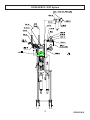
1
MCG / SSP
USER MANUAL
Multi-Color Gel-Coat System
5845 WEST 82ND STREET
INDIANAPOLIS, INDIANA
46278 U.S.A.
Phone (317) 875-5592
Fax
(317) 875-5456
Email [email protected]
Web www.glascraft.com
Table Of Contents
Introduction
About This Manual.................................................................................................................................................... 1
Parts & Illustrations
Standard Equipment ................................................................................................................................................
20300-00 Assy. drawings .........................................................................................................................................
AM-500-02 Air Motor Assy. .......................................................................................................................................
20240-00 Fluid Section Assy. ...................................................................................................................................
GAM-268-01 Material Pick-Up Kit ............................................................................................................................
LPA-165 Catalyst Bottle ...........................................................................................................................................
MCG / SSP Optional Equipment ..............................................................................................................................
2
3
10
11
13
14
15
Safety
Operating Your Polyester System Safety ................................................................................................................. 22
Operation
Before Operating The System ..................................................................................................................................
Start-up Instructions .................................................................................................................................................
Color Change Procedure .........................................................................................................................................
Shut–down Instructions ............................................................................................................................................
Routine Care ............................................................................................................................................................
32
33
36
38
38
Notes .......................................................................................................................................... 40
Limited Warranty Policy ........................................................................................................... 43
If You Have An Equipment Problem ........................................................................................ 44
For Your Reference ....................................................................................INSIDE BACK COVER
Introduction
About This Manual
Before operating, maintaining or servicing any
GlasCraft system, read and understand all of
the technical and safety literature provided with
GlasCraft products. If you do not have the proper or related manuals and safety literature for
your GlasCraft system, contact your GlasCraft
distributor or GlasCraft, Inc.
made from the GlasCraft assembly instructions
provided.
This manual provides information for the assembly, operation, maintenance and service of this
GlasCraft product as used in a typical configuration. While it lists standard specifications and
procedures, some deviations may be found.
In this GlasCraft technical and safety publication, the following advisories will be provided
where
appropriate:
In order to provide our users with the most upto-date technology possible, we are constantly
seeking to improve products. If technological
change occurs after a product is on the market,
we will implement that technology in future production and, if practical, make it available to current users as a retrofit, up-date or supplement.
If you find some discrepancy between your unit
and the available documentation, contact your
GlasCraft distributor to resolve the difference.
GlasCraft, Inc. reserves the right to change or
modify this product as it deems necessary.
NOTE
Is information about the procedure in progress.
CAUTION
Is imperative information about equipment
protection.
WARNING
Is imperative information about personal safety.
Careful study and continued use of this manual
will provide a better understanding of the equipment and process, resulting in more efficient
operation, longer trouble-free service and faster,
easier troubleshooting.
The information in this document is intended
only to indicate the components and their normal
working relationship typical use. Each assembly
should be directed by a GlasCraft distributor or
1
Standard Equipment
MODEL # 20300-00
MCG/SSP Standard Equipment
Part
Number
Description
17440-00
Grounding Clamp Assembly
1392
User Manual
GAM-268-01
Material Pump Pick-Up Kit
LPA-147-2150
Spray Tip
2
20300-00 MCG / SSP System
3
REVISION W
20300-00 MCG / SSP System
4
REVISION W
20300-00 MCG / SSP System
5
REVISION W
CJ-154
O-RING
20300-00 MCG / SSP System
* *
6
*
REVISION W
20300-00 MCG / SSP System
*
*
*
*
*
*
*
*
*
*
* NOTE - CE Guard kit p/n: 22349-00 is used for
7
European standards.
REVISION W
20300-00 MCG / SSP System Parts List
Part
Number
Description
AM-500-02
5” AIR MOTOR
CJ-153
O-RING
20221-00
BALL VALVE
GAM-268-01
PICK-UP TUBE
20234-00
CART STANDOFF
LPA-163
CAM FOLLOWER
20240-00
FLUID SECTION
LPA-165
CATALYST JUG
20243-00
AIR MOTOR END STOP
LPA-169
BOTTLE SUPPORT
20244-00
AIR MOTOR END STOP
MPB-208
AIR FILTER
20248-00
MOUNTING PLATE
P33-19
EXHAUST SILENCER
20249-00
SLIDE MOUNT
SM
SERVICE MANUAL
20250-00
SLIDE PLATE FASTENER
SSP-112
PLATE EXTENSION
20251-00
TIE PLATE
SSP-113
PLATE ADAPTER
20252-00
CASTER PLATE
SSP-114
SLAVE SLIDER
20253-00
FLUID SECTION MOUNTING PLATE
EXPANDABLE SLEEVING
Part
Number
Description
20195-25
MATERIAL HOSE
SSP-115
SLAVE PUMP DRIVE ARM
20254-00
SSP-116
HEX ADAPTER
20258-00
ELBOW FITTING
SSP-148
RELEASE PIN
20259-00
QUICK CONNECT BODY
SSP-149-01
LOCKING DETENT PIN
20260-00
BLEED HOSE
SSP-157-01
CALIBRATION DECAL
20261-00
QUICK CONNECT STEM
SSP-159
PIVOT KNOB
20655-04
ELBOW FITTING
SSP-161
SLAVE LOCK
20793-00
BALL VALVE
SSP-162
COMPRESSION SPRING
21201-00
SYSTEM OPERATION DECAL
SSP-163
PIVOT HANDLE
21202-00
FITTING
SSP-164
SLIDER INSERT
21203-00
POLYURETHANE TUBING
SSP-165
SLIDER LOCK
21402-00
LOCKOUT VALVE
SSP-166
CLAMPING HANDLE
21420-00
MOUNTING PLATE GUARD
10080-01
FITTING
21421-00
OPERATION BRACKET
10080-03
FITTING
21465-44C
STUD
1017-00
FITTING
22038-01
SPRING PLUNGER
12958-03
GASKET FITTING
22039-01
RATCHET BOX WRENCH
16028-03
HITCH PIN
22191-00
LOCKING SWIVEL CASTER
1625-23
PIPE PLUG FITTING
22331-00
SSP MOUNTING PLATE
17390-04
WASHER
22332-00
SSP MOUNTING PLATE
17440-00
GROUNDING CLAMP
22333-00
ADAPTER
17866-00
PNEUMATIC SILENCER
22334-00
STANDOFF
22335-00
SPACER
18199-02
AIR REGULATOR
18245-01
HEAT SHRINK TUBING
22339-00
MCG MANIFOLD DECAL
18318-02
AIR GAUGE
3165
BALL VALVE
19616-00
SWIVEL CASTER
3923-02
SPIRAL WRAP
19845-00
LITERATURE KIT
4342-04
ELBOW FITTING
20031-00
MANIFOLD BLOCK
7486-07
FLAT WASHER
20111-00
ADAPTER
7486-08
FLAT WASHER
20186-00
MATERIAL DECAL
7486-14
FLAT WASHER
20188-20C
SCREW
7733-14
HEX NUT
20188-28C
SCREW
7733-17
HEX NUT
8
REVISION W
20300-00 MCG / SSP System Parts List
Part
Number
Description
7733-17
HEX NUT
7734-06
LOCK WASHER
7734-07
LOCK WASHER
7734-10
LOCK WASHER
7734-12
LOCK WASHER
7957-32C
SCREW
7957-64C
SCREW
8115-03
PIPE FITTING
8155-48C
SCREW
8156-24C
SCREW
8156-32C
SCREW
9672-12
PIPE FITTING
9704-11
TUBING
9944-24C
SCREW
9944-32C
SCREW
9945-32C
SCREW
9945-48C
SCREW
9955-24C
SCREW
9955-56C
SCREW
9
REVISION W
AM-500-02 Air Motor Assembly
10
REVISION S
20240-00 Fluid Section
11
REVISION BB
20240-00 Fluid Section Parts List
Part
Number
Description
Qty.
FM-507
VALVE SEAT
2
GAM-176
RETAINING RING
1
11021-23
PIPE PLUG
1
11021-24
PIPE PLUG
1
13867-49
O-RING
2
13867-50
O-RING
1
13867-51
O-RING
1
13867-56
O-RING
1
14626-00
FITTING
1
14626-01
FITTING
1
19830-00
SURGE CHAMBER
1
19832-00
FOOT VALVE HOUSING
1
19833-00
VALVE FOOT SPACER
1
19834-01
VALVE BODY ADAPTER
1
20284-00
PUMP SHAFT
1
20496-00
QUICKSLIDE COUPLING
1
20999-02
WASHER
1
21188-00
PIPE TEE
1
21191-F
FLUID FILTER
1
21192-00
BALL VALVE
1
21230-00
LOWER CYLINDER
1
21433-01
ELBOW FITTING
1
21481-00
HOUSING SEAL
1
21482-00
HIGH VISCOSITY SEAL
1
23001-00
COMPRESSION SPRING
1
2594-44
ROLL PIN
1
346-TB
CYLINDER MATERIAL CUP
1
4342-23
ELBOW FITTING
1
7486-07
WASHER
4
7597-07
FITTING
1
7733-14
HEX NUT
4
7734-07
LOCK WASHER
4
834-1
CYLINDER PUMP ADAPTER
1
844
LOWER CUP VALVE BODY
1
845
LOWER CUP SPACER
1
8462-13
FITTING
1
8462-17
FITTING
1
850
BALL VALVE
2
852
LOWER CUP RETAINER NUT
1
854
VALVE BODY SPACER
1
9945-48C
SCREW
4
12
REVISION BB
GAM-268-01 Material Pick-Up Kit
Part
Number
13
Description
Qty.
20394-00
PICK-UP TUBE
1
20395-00
ELBOW FITTING
1
20397-01
MESH FILTER
1
20398-02
MATERIAL HOSE
1
REVISION D
LPA-165 Catalyst Bottle
Part
Number
14
Description
Qty.
LPA-167-1
BOTTLE
1
LPA-172
SCREEN
1
LPA-176
CAP
1
21039-00
TUBE ADAPTER
1
21040-00
ELBOW FITTING
1
21044-01
SEAL
1
21045-01
HEX NUT
1
9704-11
TUBING
5
REVISION N
MCG / SSP Optional Equipment
Spray Guns
Part
Number
Description
23550-00
INDY DISPENSE GUN
23560-00
INDY GEL HEAD KIT
23590-00
INDY-X GELCOAT GUN
LPA-100
AAC SPRAY GUN
23570-00
FORMULA GUN
Catalyst Pump
Part
Description
Number
SSP-190-02
CATALYST SLAVE PUMP
Additional Color
Part
Description
Number
20265-00
HARDWARE PARTS KIT
20266-00
FLUID SECTION KIT
Chopper
Part
Number
Description
22352-00
INDY GEL CHOPPER KIT
3WPG-10-K
LPA2-100 CHOPPER KIT
Repair Parts Kits
AM-500-02
20240-00
SSP
AIR MOTOR
FLUID SECTION
CATALYST SLAVE PUMP
20101-00
21570-00
LPA-190-SK
NOTE
See gun manual for repair kits.
NOTE
When adding “ODD” number colors (i.e. third color, fifth color, etc.), you will need one Hardware Kit and one Fluid Section
Kit.
When adding “EVEN” number colors (i.e. fourth color, sixth color, etc.), you will need only one Fluid Section Kit.
Material Spray Nozzles
Refer to spray gun manual to order optional spray Tip(s) that meet your spray requirements.
15
MCG / SSP Optional Equipment Connection Diagrams
ATOMIZE TUBING
AAC TUBING
GEL-COAT
16
MCG / SSP Optional Equipment Connection Diagrams
ATOMIZE TUBING
AAC TUBING
17
MCG / SSP Optional Equipment Connection Diagram
ATOMIZE TUBING
AAC TUBING
18
MCG / SSP Optional Equipment Connection Diagram
AAC TUBING
SOLVENT AIR
19
SOLVENT
MCG / SSP Optional Equipment Connection Diagram
TOP VIEW
B-410 *
*
*
*
*
*
*
*
~
~
~
~
~
AAC TUBING
~
~
~
~
SOLVENT
~
~
~
~
SOLVENT AIR
~
*
20
MCG / SSP Optional Equipment Connection Diagram
B-410 *
9704-03 ~
TOP VIEW
*
~
*
*
*
*
~
~
*
~
~
~
~
~
~
~
~
~
~
~
~
~
~
~22356-00 FORMULA GEL SCREW ON OPTION WITH
*22356-01 CHOPPER OPTION
NOTE - Remove: 23765-00 Chopper mounting assembly and place 7716-06C set screw in middle tapped
hole - (USE LOCTITE MEDIUM STRENGTH TO KEEP FROM LEAKING)
Reason: To remove extra weight and bulk from the gun, for gelcoat application. See 23750-00 Formula gun manual
for more information.
21
MCG / SSP Optional Equipment Additional Color
Installation Instructions
3. Mount fluid section kit as shown.
1. Remove end stop plate from existing track assembly.
CAUTION
2. Assemble hardware kit components as shown.
Be certain to assemble End Stop Plate, P/N 20244-00, to
new Fluid Section Mounting Plate, P/N 20253-00, before
completing assembly.
4. Assemble additional track assembly to existing track
assembly. Tighten all bolts and nuts securely.
EXISTING
SYSTEM
NOTE
Tighten Bolts and Nuts ONLY finger-tight until additional
track assembly is fitted to existing track assembly.
22
OPTIONAL
ADDITIONAL
TRACK
ASSEMBLY
MCG / SSP Optional Equipment Additional Color
5. Assemble material valve and Q.D. Fitting onto
material Hose.
CJ-154 O-RING
O-RING
6. Install Material Hose, Recirculation Hose, and Material Pick-Up Kit, P/N GAM-268-01.
CAUTION
Be certain that all fittings, bolts and nuts are tightened
securely before operating new Fluid Section Assembly.
7. Follow Start-Up Instruction steps 5 through 13 for
initial Fluid Section priming.
8. When priming process is complete, new Fluid Section is ready for use.
23
Safety
Operating Your Polyester System
Safely
particularly Paragraph (m) Organic Peroxides
and Dual Component Coatings.
1.0 Introduction
Other standards and recognized authorities to consult are the National Fire Protection Association
(NFPA) bulletins as follows:
Any tool, if used improperly, can be dangerous.
Safety is ultimately the responsibility of those using
the tool. In like manner, safe operation of polyester processes is the responsibility of those who use
such processes and those who operate the equipment. This manual outlines procedures to be followed in conducting polyester operations safely.
• NFPA No. 33 Chapter 14, Organic Perox
ides and Dual Component Materials
• NFPA No. 63 Dust Explosion Prevention
• NFPA No. 70 National Electrical Code
• NFPA No. 77 Static Electricity
• NFPA No. 91 Blower and Exhaust System
• NFPA No. 654 Plastics Industry Dust
Hazards
• Type of Fire Extinguishing equipment
recommended :
This system has been specifically designed for use
of Polyester Resin ,Gel-Coat ,and Methyl Ethyl Ketone Peroxides (MEKP) applications. Other formulations or blends considered for use in this equipment is strictly prohibited without the expressed
consent by GlasCraft Inc.
Fire Extinguisher -- code ABC ,rating number
4a60bc. Extinguishing Media -- Foam, Carbon Dioxide, Dry Chemical, Water Fog.
GlasCraft, Inc. cannot eliminate every danger nor
foresee every circumstance that might cause an injury during equipment operation. Some risks, such
as the high pressure liquid stream that exits the
spray tip, are inherent to the nature of the machine
operation and are necessary to the process in order to manufacture the end-product. For this reason, ALL personnel involved in polyester operations
should read and understand the Safety Manual. It is
very important for the safety of employees involved
in the operation that equipment operators, maintenance and supervisory personnel understand the
requirements for safe operation.
Copies of the above bulletins are available, at a
nominal charge from:
National Fire Protection Association
470 Atlantic Avenue
Boston, MA 02210
Research Report No. 11 of the American Insurance
Association deals with “Fire, Explosion and Health
Hazards of Organic Peroxides”. It is published by...
American Insurance Association
85 John Street
New York, New York 10038
Each user should examine his own operation, develop his own safety program and be assured that
his equipment operators follow correct procedures.
GlasCraft hopes that this manual is helpful to the
Local codes and authorities also have standards to
be followed in the operation of your spraying equipment. Your insurance carrier will be helpful in answering questions that arise in your development of
safe procedures.
user and recommends that the precautions in this
manual be included in any such program. GlasCraft
recommends this Safety Manual remain on your
equipment at all times for your personnel safety.
1.2 Personnel Safety Equipment
In addition to the manual, GlasCraft recommends
that the user consult the regulations established under the Occupational Safety & Health Act (OSHA),
particularly the following sections:
•
•
•
GlasCraft recommends the following Personal
Safety Equipment for conducting safe operations of
the Polyester Systems:
1910.94 Pertaining to ventilation.
1910.106 Pertaining to flammable liquids.
1910.107 Pertaining to spray finishing
operations,
24
Safety
MEKP is not a single chemical. Various polymeric
forms may exist which are more or less hazardous with
respect to each other. These differences may arise
not only from different molecular structures (all are,
nevertheless, called “MEKP”) and from possible trace
impurities left from the manufacture of the chemicals,
but may also arise by contamination of the MEKP with
other materials in its
GlasCraft recommends that the user consult the state
and local regulations established for all Safety equipment listed.
2.0 Material Safety
2.1 Hazards Associated with
Laminating Operations
storage or use.Even a small amount of contamination
with acetone, for instance, may produce an extremely
shock-sensitive and explosive compound.
The major hazards which should be guarded against in
polyester laminating operations are those associated
with:
Contamination with promoters, or materials
containing promoters, such as laminate sandings,
or with any readily oxidizable material, such as
brass or iron, will cause exothermic “redox”
reactions which can become explosive in nature.
Heat applied to MEKP, or heat build-up from
contamination reactions can cause it to reach
what is called its Self-Accelerating Decomposition
Temperature (SADT).
1. The flammability and explosion dangers of the
catalyst normally used - Methyl Ethyl Ketone
Peroxide (MEKP).
2. The flammability dangers of clean-up solvents
sometimes used (GlasCraft recommends that
clean-up solvents be nonflammable), and of resin
diluents used, such as styrene.
Researchers have reported measuring pressure ratesof-rise well in excess of 100,000 psi per second when
certain MEKP’s reach their SADT. (For comparison, the
highest pressure rate-of-rise listed in NFPA Bulletin No.
68, “Explosion Venting”, is 12,000 psi per second for
an explosion of 12% acetylene and air. The maximum
value listed for a hydrogen explosion is 10,000 psi per
second.)
3. The flammability dangers of catalyst diluents, if
used. (GlasCraft recommends that catalyst not
be diluted.)
4. The flammability dangers of the uncured
liquid resins used.
5. The combustibility dangers of the cured laminate,
accumulations of overspray, and laminate
sandings.
Some forms of MEKP, if allowed to reach their SADT,
will burst even an open topped container. This
suggests that it is not possible to design a relief valve
to vent this order of magnitude of pressure rate-of-rise.
The user should be aware that any closed container,
be it a pressure vessel, surge chamber, or pressure
accumulator, could explode under certain conditions.
There is no engineering substitute for care by the user
in handling organic peroxide catalysts.
6. The toxicity dangers of all the chemicals used in
laminating operations with respect to ingestion,
inhalation and skin and eye hazards.
2.2
Catalyst
If, at any time, the pressure relieve valve on top of the
catalyst tank should vent, the area should be evacuated
at once and the fire department called. The venting
could be the first indication of a heat, and therefore,
pressure build-up that could eventually lead to an
explosion. Moreover, if a catalyst tank is sufficiently
full when the pressure relief valve vents, some
catalyst may spray out, which could cause eye injury.
For this reason, and many others, anyone whose job
puts them in an area where this vented spray might
go, should always wear full eye protection even when
laminating operations are not taking place.
(Methyl Ethyl Ketone Peroxide)
MEKP is among the more hazardous materials found
in commercial channels. The safe handling of the
“unstable (reactive)” chemicals presents a definite
challenge to the plastics industry. the highly reactive
property which makes MEKP valuable to the plastics
industry in producing the curing reaction of polyester
resins also produces the hazards which require
great care and caution in its storage, transportation,
handling, processing and disposal.
25
Safety
Safety in handling MEKP depends to a great extent on
employee education, proper safety instructions and safe
use of the chemicals and equipment. Workers should
be thoroughly informed of the hazards that may result
from improper handling of MEKP, especially in regards
to contamination, heat, friction and impact. They should
be thoroughly instructed regarding the proper action
to be taken in the storage, use and disposal of MEKP
and other hazardous materials used in the laminating
operation.
In addition, users should make every effort to:
1. Store MEKP in a cool, dry place in original
containers away from direct sunlight and away
from other chemicals.
with copious quantities of clean water and
disposed of in accordance with the catalyst
manufacturer’s instructions.
The extent to which the user is successful in
accomplishing these ends and any additional recommendations by the catalyst manufacturer determines
largely the safety that will be present in his operation.
2.3 Clean-Up Solvents and Resin
Diluents
WARNING
A hazardous situation may be present in your pressurized fluid system!
Hydrocarbon Solvents can cause an explosion when
used with aluminum or galvanized components in a
closed (pressurized) fluid system (pumps, heaters, filters, valves, spray guns, tanks, etc.)
The explosion could cause serious injury, death and/or
substantial property damage.
Cleaning agents, coatings, paints, etc. may contain
Halogenated Hydrocarbon Solvents.
Some GlasCraft spray equipment includes aluminum or
galvanized components and will be affected by
Halogenated Hydrocarbon Solvents.
2. Keep MEKP away from heat, sparks and open
flames.
3. Prevent contamination of MEKP with other
materials, including polyester overspray and
sandings, polymerization accelerators and
promoters, brass, aluminum and nonstainless steels.
4. Never add MEKP to anything that is hot, since
explosive decomposition may result.
5. Avoid contact with skin, eyes and clothing.
Protective equipment should be worn at all
times. During clean-up of spilled MEKP,
personal safety equipment, gloves and eye
protection must be worn. Fire fighting
equipment should be at hand and ready.
There are three key elements to the Halogenated
Hydrocarbon (HHC) solvent hazard.
6. Avoid spillage, which can heat up to the point
of self-ignition.
1. The presence of HHC solvents. 1,1,1Trichloroethane and Methylene Chloride are the
most common of these solvents. However, other
HHC solvents are suspect if used; either as part
of paint or adhesives formulation, or for clean-up
flushing.
7. Repair any leaks discovered in the catalyst
system immediately, and clean up the leaked
catalyst at once in accordance with the
catalyst manufacturer’s instructions.
2. Aluminum or Galvanized Parts. Most handling
equipment contains these elements. In contact
with these metals, HHC solvents could generate
a corrosive reaction of a catalytic nature.
8. Use only original equipment or equivalent parts
from GlasCraft in the catalyst system
(i.e.: hoses, fittings, etc.) because a dangerous
chemical reaction may result between
substituted parts and MEKP.
3. Equipment capable of withstanding pressure.
When HHC solvents contact aluminum or galva
nized parts inside a closed container such as a
pump, spray gun, or fluid handling system, the
chemical reaction can, over time, result in
a build-up of heat and pressure, which can reach
explosive proportions. When all three elements
are present, the result can be an extremely
violent explosion. the reaction can be sustained
with very little aluminum or galvanized metal; any
amount of aluminum is too much.
9. Catalyst accumulated from the purging of
hoses or the measurement of fluid output
deliveries should never be returned to the
supply tank. such catalyst should be diluted
26
Safety
The reaction is unpredictable. Prior use of an HHC solvent without incident (corrosion or explosion) does NOT
mean that such use is safe. These solvents can be dangerous alone (as a clean-up or flushing agent) or when
used as a component or a coating material. There is no
known inhibitor that is effective under all circumstances.
Furthermore, the mixing of HHC solvents with other
materials or solvents, such as MEK, alcohol, and toluene, may render the inhibitors ineffective.
The use of reclaimed solvents is particularly hazardous.
Reclaimers may not add any inhibitors. Also, the possible presence of water in reclaimed solvents could feed
the reaction.
Anodized or other oxide coatings cannot be relied upon
to prevent the explosive reaction. Such coatings can
be worn, cracked, scratched, or too thin to prevent contact. There is no known way to make oxide coatings or
to employ aluminum alloys which will safely prevent the
chemical reaction under all circumstances.
Several solvent suppliers have recently begun promoting
HHC solvents for use in coating systems. The increasing
use of HHC solvents is increasing the risk. Because of
their exemption from many State Implementation Plans
as Volatile Organic Compounds (VOC’s), their low flammability hazard, and their not being classified as toxic or
carcinogenic substances, HHC solvents are very desirable in many respects.
WARNING
Do not use Halogenated Hydrocarbon solvents in pressurized fluid systems having aluminum or galvanized
wetted parts.
NOTE
GlasCraft is aware of NO stabilizers available to prevent
Halogenated Hydrocarbon solvents from reaction under
all conditions with aluminum components in a closed
fluid system.
TAKE IMMEDIATE ACTION...
Halogenated Hydrocarbon solvents are dangerous
when used with aluminum components in a closed fluid
system.
supplier regarding the best non-flammable clean-up solvent with the heat toxicity for your application.
If, however, you find it necessary to use flammable
solvents, they must be kept in approved, electrically
grounded containers.
Bulk solvent should be stored in a well-ventilated, separate building, 50 feet away from your main plant.
You should allow only enough solvent for one day’s use
in your laminating area.
“NO SMOKING” signs must be posted and observed in
all areas of storage or where solvents and other flammable materials are used.
Adequate ventilation (as covered in OSHA Section
1910.94 and NFPA No. 91) is important wherever solvents are stored or used, to minimize, confine and exhaust the solvent vapors.
Solvents should be handled in accordance with OSHA
Section 1910.106 and 1910.107.
2.4 Catalyst Diluents
GlasCraft spray-up and gel-coat systems currently produced are designed so that catalyst diluents are not required. GlasCraft, therefore, recommends that diluents
not be used. This avoids the possible contamination
which could lead to an explosion due to the handling and
mixing of MEKP and diluent. In addition, it eliminates any
problems from the diluent being contaminated through
rust particles in drums, poor quality control on the part of
the diluent supplier, or any other reason. If, however, diluents are absolutely required, contact your catalyst supplier and follow his instructions explicitly. Preferably, the
supplier should premix the catalyst to prevent possible
“on the job” contamination while mixing.
WARNING
If diluents are not used, it should be remembered that
catalyst spillage, gun, hose and packing leaks are potentially more hazardous, since each drop contains a higher
concentration of catalyst, and therefore will react quicker
with overspray and the like.
Consult your material supplier to determine whether
your solvent or coating contains Halogenated Hydrocarbon Solvents.
2.5 Uncured Liquid Resin
GlasCraft recommends that you contact your solvent
Resin should be stored in a well ventilated building at
least 50 feet from your main plant. In addition, the storage temperature should not exceed 75 degrees F.
27
Safety
In your main plant, store only enough resin for one day’s
production.
“NO SMOKING” signs must be posted and observed in
all areas where resin is stored and/or used.
Refer to OSHA Section 1910.94, 1910.106, 1910.107
and consult resin suppliers for more detailed information.
Adequate ventilation (as covered in OSHA Section
1910.94 and NFPA No. 91) is important wherever solvents are stored or used, to minimize, confine and exhaust the solvent vapors.
Resin must never be stored in an area where MEKP is
stored or used.
Open-top drums should not be used, due to possible
contamination and possible catalyzation from overspray
or spillage of MEKP into drum, which could not only severely damage the polyester spray system, but might
also cause the drum of resin to ignite.
When spraying test patterns or purging the gun, always
remove the test samples and waste from the building immediately and dispose of them in accordance with your
material supplier’s recommendations.
2.6 Cured Laminate, Overspray and
Laminate Sandings Accumulation
Remove all accumulations of overspray, FRP sandings,
etc. from the building as they occur. If this waste is allowed to build up, spillage of catalyst is more likely to
start a fire, In addition, the fire would burn hotter and
longer.
Floor coverings, if used, should be non-combustible.
Spilled or leaked catalyst may cause a fire if it comes in
contact with an FRP product, oversprayed chop or resin,
FRP sandings or any other material with MEKP.
To prevent this spillage and leakage, you should:
4. Arrange the hoses and fiberglass roving guides
so that the fiberglass strands DO NOT rub
against any of the hoses at any point. If allowed
to rub, the hoses may be cut through, causing a
hazardous leakage of material which could increase the danger of fire. Also the material may
spew onto personnel in the area.
2.7 Toxicity of Chemicals
GlasCraft recommends that you consult OSHA Sections
1910.94, 1910.106, 1910.107 and NFPA No. 33, Chapter 14, and NFPA No. 91.
Contact your chemical supplier(s) and determine the
toxicity of the various chemicals used, as well as the
best methods to prevent injury, irritation and danger to
personnel.
Also determine the best methods of first aid treatment for
each chemical used in your plant.
2.8 Treatment of Chemical Injuries
Great care should be used in handling the chemicals
(resins, catalyst and solvents) used in polyester systems.
Such chemicals should be treated as if they hurt your
skin and eyes and as if they are poison to your body. For
this reason, GlasCraft recommends the use of protective
clothing and eye wear in using polyester systems.
However, users should be prepared in the event of such
an injury. Precautions include:
1. Know precisely what chemicals you are using and
obtain information from your chemical supplier on
what to do in the event the chemical gets
onto your skin or into the eyes, or is swallowed.
2. Keep this information together and easily available
so that it may be used by those administering first
aid or treating the injured person.
1. Maintain your GlasCraft System. Check the gun
several times daily for catalyst and resin packing
or valve leaks. REPAIR ALL LEAKS IMMEDIATELY.
2. Never leave the gun hanging over, or lying inside
the mold. A catalyst leak in this situation would
certainly damage the part, possible the mold, and
may cause a fire.
3. Inspect resin and catalyst hoses daily for wear or
stress at the entry and exits of the boom sections
and at the gun and fittings. Replace if wear or
weakness is evident or suspected.
3. Be sure the information from your chemical
supplier includes instructions on how to treat
any toxic effects the chemicals may have.
28
Safety
3.1 Emergency Stop Procedures
WARNING
The following steps should be followed in order to
stop the machinery in an emergency situation:
Contact a doctor immediately in the event of any injury and give him the information you have collected.
If your information includes first aid instructions, administer first aid immediately while you are contacting the doctor.
1. The yellow air valve located where the air
enters the machine should be pushed to
the “OFF” (closed) position. To do this simply
push on the lever protruding out the side of
the valve. This will also cause all the system
air to bleed out of the system in a matter of a
few seconds thus making the system
incapable of operating.
Fast treatment of the outer skin and eyes that contact such chemicals generally includes immediate
and thorough washing of the exposed skin and immediate and continuous flushing of the eyes with
lots of clean water for at least 15 minutes or more.
These general instructions of first aid treatment,
however, may be incorrect for some chemicals; that
is why you must know the chemicals and treatment
before an accident occurs. Treatment for swallowing a chemical frequently depends upon the nature
NOTE
Step 2 is a precautionary step and should be followed whenever the emergency stop valve is activated to the stop mode. Failure to do so will damage
regulators and components when reactivating to the
ON position.
of the chemical.
NOTE
2. Turn all system regulators to OFF (counterclockwise) position.
Refer to your System User Manual for complete and
detailed operating instructions and service information.
NOTE
Verify that the Catalyst Pressure Relief Line and the
Resin Return Line are secured before relieving catalyst and resin fluid pressure.
3.0 Equipment Safety
WARNING
3. Catalyst pressure in the Slave Pump can be
eliminated by rotating the yellow valve handle
on the Slave Pump 90 degrees to the “ON”
position.
GlasCraft suggest that personnel safety equipment
such as EYE GOGGLES, GLOVES, EAR PROTECTION, and RESPIRATORS be worn when servicing
or operating this equipment. Ear protection should
be worn when operating a fiberglass chopper to protect against hearing loss since noise levels can be
as high as 116 dB (decibels).
This equipment should only be operated or serviced
by technically trained personnel!!!
NOTE
The “ON” position the valve handle is parallel (in
line) with the valve body .
The “OFF” position the valve handle is perpendicular (across) the valve body.
WARNING
4. Resin pressure can be eliminated by rotating
the yellow handled valve on the bottom of
the fluid filter 90 degrees. Place a container
under the bottom of the valve to catch any
resin that is ejected from the valve.
Never place fingers, hands, or any body part near or
directly in front of the spray gun fluid tip. The force of
the liquid as it exits the spray tip can cause serious
injury by shooting liquid through the skin. NEVER
LOOK DIRECTLY INTO THE GUN SPRAY TIP
OR POINT THE GUN AT OR NEAR ANOTHER
PERSON.
(TREAT THE GUN AS IF IT WERE A LOADED PISTOL)
29
Safety
3.2 General Safety Precautions
•
Do not operate Fiberglass Chopper Guns with
out protective covers in place.
• Correct packing or valve seat leaks immediately.
• Never immerse the gun in any liquid.
• Periodically check operation of catalyst alarms
to make sure they are operation properly.
• Frequently check condition of hoses. Replace worn
hoses and other parts before they fail.
• Catalyst fluid nozzles and seals MUST be in good
condition at all times to prevent internal and
external leaks. Inspect periodically and replace
as needed, or at intervals of three to four months.
Use catalyst nozzle seal only once to prevent
possible leakage of catalyst into air passages
of gun.
• Make absolutely certain that all pressure has been
relieved from the gun before disassembly from the
hoses before loosening any fittings; from the
material or catalyst pump before disassembly; from
the catalyst injector before disassembly or filling.
• If you have any doubt that fluid pressure is relieved,
call your GlasCraft distributor or GlasCraft, Inc.
before proceeding with any disassembly.
• Use only genuine GlasCraft replacement parts when
repairing your system. Substitutes may not be the
proper material or may not fit the system and may
cause dangerous operating conditions and the
failure of other components.
The following general safety precautions should be
followed when servicing or operating this equip
ment to ensure operator safety:
•
•
•
•
•
•
•
•
•
When filling catalyst container, protective eye
equipment must be worn to protect against
injuries.
Always maintain adequate material levels to
prevent loss of prime during system operation.
At the first sign of a leak, stop operations, activate emergency stop valve, back off air regulators and open all bleed valves to remove
all pressure from the gun, hoses, pump, catalyst
system and any other liquid containers.
Solvent Pot Pressure Relief:
Turn Solvent Pressure Regulator counter clock
wise (ccw) until regulator handle stops.
Open Petcock valve to bleed Solvent Tank
pressure completely.
Catalyst Injector Pressure Relief:
Refer to Catalyst Injector User Manual for
proper pressure relief.
Never operate a Fiberglass System with
fixed Pinch Point guards removed from system.
30
Safety
Never use hard materials such as wire, pins, etc., To
clear a plugged gun. Hard materials can cause permanent damage. Dab with a bristle brush, blow backwards with air until clear while wearing a protective
eye shield. Repeat as many times as necessary.
Do not perform any maintenance or repairs until you
have followed the precautions stated above. If you,
as an equipment operator or supervisor, do not feel
that you have been adequately trained or instructed
and that you lack the technical knowledge to operate
or perform maintenance on a piece of glascraft equipment, please call glascraft, inc. Before operating or
performing maintenance on the equipment.
3.3 Grounding
Grounding an object means providing an adequate
path for the flow of an electrical charge from the object to the ground. An adequate path is one that permits charge to flow from the object fast enough that
it will not accumulate to the extent that a spark can
be formed. It is not possible to define exactly what
will be an adequate path under all conditions since it
depends on many variables.
In any event, the grounding means should have
the lowest possible electrical resistance. Grounding
straps should be installed on all loose conductive
objects in the spraying area. This includes material
containers and equipment. GlasCraft recommends
grounding straps be made of AWG No. 18 stranded
wire as a minimum, and that larger wire be used
where possible. NFPA Bulletin No. 77 states that the
electrical resistance of such a leakage path may be
as low as 1 meg ohm (106 ohms) but that resistances
as high as 10,000 meg ohms will produce an adequate leakage path in some cases.
If you have any questions regarding the above precautions or any service or operation procedures, call
your glascraft distributor or glascraft, inc.
NOTICE
All statements, information and data given herein
are believed to be accurate and reliable but are presented without guaranty, warranty or responsibility of
any kind expressed or implied. The user should not
assume that all safety measures are indicated or that
other measures are not required.
Whenever flammable or combustible liquids are
transferred from one container to another, or from
one container to the equipment, both containers or
container and equipment shall be effectively bonded
and grounded to dissipate static electricity.
For further information, see National Fire Protection Association (NFPA) 77 titled “Recommended
Practice on Static Electrical”. Refer especially to Section 7-7 titled “Spray Application of Flammable and
Combustible Materials”. Check with local codes and
authorities for other specific standards that might apply to your application.
5845 WEST 82nd STREET, SUITE 102
INDIANAPOLIS, INDIANA 46728 U.S.A.
PHONE (317) 875-5592
FAX (317) 875-5456
31
Operation
NOTE
5. Close bypass valve on fluid section of pump. (Turn
clockwise to close).
Refer to specific User Manuals for detailed component
start-up and shut-down instructions.
Before Operating the System
1. Make sure all hose connections are tight and secure.
2. Make sure to remove Cap plug from bottom inlet of
Material Pump before attaching material pick-up
hose.
6. Connect main air supply to system. (GlasCraft recommends a minimum of 3/8”dia. airline.)
3. Fill Lube Cup at the top of fluid section half (½ ) full
of suitable pump lube.
7. Each new GlasCraft system has been fluid tested
at the factory. Our pump test solution is red- colored
DBP (Di-N-Butyl Phthalate). There may be a residual amount of DBP in system that should beevacuated before putting the unit into production.
During the initial start-up, ½ to 1 gallon of material
should be dispensed. This is typically adequate to
remove the test material. If desired, the fluid pump
can be flushed with a suitable cleaning solution to
evacuate DBP before priming with material.
8. Review all service manuals, which contain detailed
operation and safety instructions.
4. Make sure the ball valves on manifold are off and
regulators are dialed down to zero. (Turning regulators counter-clockwise will dial them down.)
32
Operation
9. Put pick-up wand in bucket or drum of polyester.
10. Inspect Catalyst bottle for debris; clean if necessary.
Fill catalyst supply bottle. Two gallons; maximum
amount in supply bottle.
11. Inspect pick-up hoses to make sure they are not bent.
12. Insert recirculation hoses in material drum or bucket.
Start-Up Internal Mix
2. Open main air valve at manifold.
Solvent
*Before initial operation of any internal mix
system, Ensure that the solvent flush setup is fully operational.
1. Fill solvent pot with suitable flush material.
3. Open ball valve at solvent regulator.
33
Operation
4. Dial up 90-100 psi of pressure at solvent regulator.
5. While continuing to hand prime the pump, trigger gun
into suitable collection container.
5. Using a proper collection container, open solvent flush
valve at the INDy gun. Ensure that you have proper solvent flushing at the gun.
6. Continue to hand prime the pump, with trigger pulled
and inspect the flow of catalyst from nozzle.
7. Once all air is evacuated and a steady stream of
catalystis observed, the system is primed with catalyst.
8. Release trigger and stop hand priming.
9. Solvent flush gun
Catalyst
1. Pull and rotate Pivot knob
to disengage the catalyst drive
arm.
2. Turn the catalyst slave
pump yellow ball valve to the
open position.
3. Hand prime the pump
until a steady stream of catalyst
flows back to the bottle.
4. Close the ball valve hand
stroke the pump until it developes
100-200 PSI.
34
Operation
Gel-Coat
• Confirm that you are getting a complete, consistent
and uniform mix of catalyst. If red dye catalyst is being
used, this will be easy to confirm visually.
1. Open ball valve at material regulator.
• While triggering the gun onto a test panel, visibly
inspect the fluid pressure gauge on the catalyst pump.
• The catalyst pressure should approximately match
the fluid pressure generated by the material pump.
• Example:
2. With the roller cam still unattached from slave pump
• With 11:1 pump dialed up to 20 psi at the regulator,
you will have (11x20=220) 220 psi fluid pressure.
linkage arm, slowly begin to dial up pressure at
material regulator. Between 5-15 psi, the pump will
begin to cycle. The pump will continue to fill the system with material and will stall out when the polyester arrives at the gun.
• While spraying the gun, inspect catalyst pressure
gauge to confirm catalyst pressure.
• Material viscosity, temperature, filler load, surface
tension and other factors will ultimately determine the
proper material pressure that will be required.
• With 11:1 ratio pump, GlasCraft recommends
• Because of material viscosity, size of nozzle, length
of hose and other factors, the catalyst pressure may
not exactly match material pressure.
• Catalyst pressure should be +/- 50 psi of material
pressure.
7. After confirming acceptable catalyst-to-material pres -
an initial start-up pressure of 20-25 psi.
sure, spray several test strips or panels to confirm geltime and uniform catalization. Catalyst pressure
should stay consistent and steady.
3. Dial up material pump pressure to initial start-up
pressure.
8. Inspect material dispense pattern.
4. Prime the slave pump to proper psi. depending on
9. Adjust material pressure to achieve desired pattern of
which gun is being used.
material.
5. Rotate Pivot Knob, P/N SSP-159 to Re-engage
10. Solvent-flush the gun.
catalyst drive arm.
NOTE
NOTE
It is important to remember that after releasing the
trigger, mixed catalyst and material will remain in the
head of the gun. Depending on the gel-time of the material- in a reasonably short period of time, it will be necessary to:
Pull the trigger and begin spraying again.
OR Solvent flush the gun.
There may be a small amount of air still in the material.
It will push itself out quickly.
6. Check and confirm the following points:
35
Operation
Color Change Procedure
3. Turn Main Air Supply Valve to the “off” position.
This will relieve the air pressure on the Air Motor.
1. Turn Air Control Valve clockwise to “COLOR
valve
CHANGE” position.
21201-00
cut
out
1089A
351044
C
21201-00
DECAL, OPERATION, MCG
L. LARSON
6-19-02
SIZE: (ref.): 3-5/8" X 2-5/8"
HOLE IS 3/4" DIA, LOCATED 1-13/16" FROM LEFT SIDE & 1-1/4" FROM BOTTOM.
COLOR:
TEXT - WHITE
BACKGROUND - BLACK GRADIENT
LOGO - WHITE AND 40% BLACK
MATERIAL:
ADHESIVE-BACKED WHITE POLYESTER with
CLEAR POLYESTER LAMINATE ON THE TOP OF DECAL.
2. Turn Material Valve, P/N 21192-00, from Material
4. Pull and rotate Pivot knob
Hose to Recirculating Hose (handle in vertical
position). This will relieve pressure on Material Hose.
to disengage the catalyst drive
arm.
valve
Drive arm
NOTE
Pump will cycle to down stroke and stop.
Once the pumps are in the down position, close
material valve.
5. Turn Material Valve (at gun) clockwise to “OFF”
position. Material valve should remain in “OFF”
position until color Material Hose is required again.
6. Detach Quick-Disconnect Fitting (Gun end),
P/N 20259-00, from Quick-Disconnect Fitting (Hose
end),P/N 20261-00.
CJ-154 O-RING
O-RING
36
Operation
WARNING
Material Valve MUST remain in the “OFF” position when
not in use to prevent material from leaking out of hose!
10. Tighten Lock Down Bolts securely.
NOTE
When not in use, Material Hose should be coiled and
stored in a safe, out-of-the-way location. Quick-Disconnect Fitting should be kept clean of dirt and overspray.
7. Securely attach desired Color Material Hose to back
of Spray Gun. Make certain that Material Valve
remains in “OFF” position at this time.
11. Turn Air Control Valve counter-clockwise from
“COLOR CHANGE” to ‘SPRAY” position.
8. Loosen lock down bolts, P/N 20250-00.
lock down
bolts
21201-00
cut
out
lock pin
1089A
351044
C
21201-00
DECAL, OPERATION, MCG
L. LARSON
6-19-02
SIZE: (ref.): 3-5/8" X 2-5/8"
HOLE IS 3/4" DIA, LOCATED 1-13/16" FROM LEFT SIDE & 1-1/4" FROM BOTTOM.
COLOR:
TEXT - WHITE
BACKGROUND - BLACK GRADIENT
LOGO - WHITE AND 40% BLACK
MATERIAL:
ADHESIVE-BACKED WHITE POLYESTER with
CLEAR POLYESTER LAMINATE ON THE TOP OF DECAL.
9. Slide Air Motor/Slave Pump Assembly to desired
Color Pump Fluid Section and align air motor and
fluid section shafts.
12. Turn Main Air Supply Valve slowly “On” until pump
stalls.
The lock pin should know snap-in place.
valve
37
Operation
13. Pull and rotate Pivot
NOTE
14. Turn the catalyst slave
Material Pump should be stopped with Pump Shaft in
UP position. Shaft should be cleaned of any over-spray
or foreign material.
knob to disengage the catalyst
drive arm.
See Spray Gun User manual for proper shut-down
procedures.
pump yellow ball valve to the
open position.
Material Pump Lube Cup should be emptied, cleaned
and refilled with a clean, compatible lubricant.
15. Hand prime the pump
until a steady stream of catalyst
flows back to the bottle.
NOTE
16. Close the ball valve hand
stroke the pump until it
developes 100-200 PSI.
GlasCraft recommends you contact your gel-coat or
material supplier for their recommendation of a lubricant
that will be suitable for use with your material.
17. Turn Material Valve on back of Gun to “On”
Material Pump should now be cycled so that shaft is
left in DOWN position during shut-down period.
position.
CAUTION
CJ-154 O-RING
Failure to cycle Pump Shaft to DOWN position may
result in over-spray or leaked material to dry or harden
on Shaft. When Pump is next operated, severe damage
may be done to Upper Pump Seals.
O-RING
Routine Care
18. Color Change Procedure is now complete and
normal spray operations may continue.
NOTE
GlasCraft recommends the use of
TGC FRP TOOL & GUN CLEANER for...
> cleaning of spray guns, spray tips, rollers,
brushes, hoses, etc. ...as well as any general shop
clean-up!
Shut-Down Instructions
1. Turn the “On/Off” Ball Valves on the Air Manifold to
their “Off” position.
It is recommended that the following service be
performed on a weekly basis.
1. Inspect and lubricate Catalyst Slave Pump Linkage.
(See Catalyst Slave Pump User Manual.)
2. Inspect Pump Shafts on Material and Catalyst
Pumps, making certain they are clean and free of
overspray or foreign material. Clean and lubricate as
required.
2. Pressure should be maintained on the material and
catalyst hose.
38
Operation
3. Inspect Gun Valve Needle Shafts, making certain
they are clean and free of over-spray or foreign
material. Clean and lubricate as required. (See
Spray Gun User Manual.)
Make certain all air and material valves are in their
“OFF” position.
NOTE
GlasCraft recommends that you contact your gel-coat
and/or material supplier concerning material pot-life during extended periods of shut-down. The decision as to
whether or not to leave material in your system should
be based on information from your material suppliers
as well as GlasCraft. Contact glascraft technical department for any questions.
Consult your local authorized GlasCraft distributor for
more information concerning system storage.
39
Notes
40
Notes
41
Notes
42
Limited Warranty Policy
GLASCRAFT, INC. (“GlasCraft”) warrants to the original Purchaser of GlasCraft manufactured equipment
and parts, that all GlasCraft manufactured equipment and parts will conform to their published written specifications and
be free of defects in workmanship and material for a period of one (1) year from the original date of installation. GlasCraft
makes no warranty to anyone other than the original Purchaser.
If any GlasCraft manufactured part or equipment is found to be defective in workmanship or material within the one-year
period from the date of installation, as determined solely by GlasCraft, GlasCraft, in its sole discretion, will either repair
or replace the defective part or equipment at GlasCraft’s cost, including freight charges both ways, or credit or refund the
purchase price for the defective equipment or part.
A warranty claim will be honored only when:
1. GlasCraft has been informed, in writing, of any such defect in workmanship or material within ten (10) days
after discovery by the original Purchaser;
2. An official of GlasCraft has issued a return authorization number; and
3. The claimed defective equipment or part has been returned to GlasCraft by the original Purchaser, freight
prepaid (with proper return authorization number(s) attached), to: GlasCraft, Inc., 5845 West 82nd Street,
Suite 102, Indianapolis, IN 46278, U.S.A.
This warranty shall not apply to any equipment or parts that have been altered or repaired by anyone other than GlasCraft
or to defects or damage resulting from improper installation, misuse, negligence, accident, or use not specified by
GlasCraft. This warranty shall not apply to any equipment where any parts or components were replaced by any parts
or components not manufactured or supplied by GlasCraft. The decision by GlasCraft shall be conclusive and binding
on Purchaser.
GlasCraft does not warrant that any equipment or parts sold to Purchaser meet or comply with any local, state, federal,
or other jurisdiction’s regulations or codes. GlasCraft does not warrant that any equipment or part sold to Purchaser,
when used individually or in concert with any other part, equipment, device, component or process, does not infringe on
any patent rights of any third party. GlasCraft only warrants that it has no specific knowledge of any such infringement.
GlasCraft makes no warranty as to any parts or equipment manufactured by others. Purchaser shall look solely and
only to the manufacturer of such parts or equipment with respect to any warranty claims. GlasCraft hereby assigns to
Purchaser the original manufacturer’s warranties to all such equipment and parts, to the full extent permitted.
THE AFORESAID WARRANTY IS IN LIEU OF ALL OTHER WARRANTIES, EXPRESS OR IMPLIED. SPECIFICALLY THERE ARE NO WARRANTIES OF MERCHANTABILITY OR FITNESS
FOR A PARTICULAR PURPOSE, WHICH WARRANTIES ARE SPECIFICALLY DISCLAIMED.
GlasCraft shall not be liable for any loss or expense resulting from damage or accidents caused by improper use or application of materials manufactured or sold by GlasCraft or its distributors or agents.
UNDER NO CIRCUMSTANCES SHALL GLASCRAFT’S LIABILITY EXCEED THE AMOUNT PURCHASER PAID FOR THE CLAIMED DEFECTIVE EQUIPMENT OR PART. UNDER NO CIRCUMSTANCES SHALL GLASCRAFT BE LIABLE FOR INCIDENTAL OR CONSEQUENTIAL DAMAGES OR FOR LOST PROFITS.
No action arising from or relating to any goods manufactured by or purchased from GlasCraft may be brought more than
one (1) year after the cause of action accrues.
43
If You Have An Equipment Problem............
If you have a problem that requires Distributor
or GlasCraft Service Department help, gather the
following information BEFORE you pick-up the
telephone.
Model No.
Serial No.
SPRAY GUN
MATERIAL PUMP
CATALYST DELIVERY SYSTEM
CHOPPER
TYPE OF MATERIAL BEING SPRAYED
TYPE OF CATALYST BEING SPRAYED
CATALYST PERCENTAGE
%
SYSTEM GAUGE PRESSURES
AAC
PSI
ATOMIZING AIR
PSI
MATERIAL PUMP
PSI
MAIN AIR LINE PRESSURE AT SYSTEM
PSI
CFM
MAIN AIR LINE VOLUME
COMPRESSOR SIZE
HP
INCHES
COMPRESSOR TO SYSTEM SUPPLY LINE SIZE
Have a general equipment or operation question?
You can contact the GlasCraft Service Department via E-Mail at [email protected]
44
For Your Reference
DATE PURCHASED __________________________________________________
DISTRIBUTOR ______________________________________________________
______________________________________________________
______________________________________________________
CONTACT
______________________________________________________
PHONE
______________________________________________________
Manufacturers of ...
Fiberglass Fabrication Systems with High Transfer Efficiency and Low Emissions,
Systems for Low or High Production,
and Systems to Improve Quality and Profitability
INDy Series
“Internal-Mix Non-Atomized Dispense Systems”
… featuring INDy Nozzle Wet-Out, Chopper &
Pressure-Fed Roller Systems and Equipment
-------------------------------------------------------------------------------------------------------------------
APD
Spartan
ADHESIVE DISPENSING SYSTEM
RESIN TRANSFER MOLDING SYSTEM
------------------------------------------------------------------------------------------------------------------Micro ll, Maxi ll, Super Maxi,
SPRAY, POUR & INJECT
Mini III, MX, MX II, MH & MH II
FIXED & VARIABLE RATIO SYSTEMS and
...featuring the patented Probler Spray/Pour Gun
EQUIPMENT FOR POLYURETHANE FOAMS,
COATINGS and POLYUREAS
For more information concerning any of these GlasCraft products,
contact your local authorized GlasCraft distributor, or
Quality and Performance…
GENUINE GLASCRAFT
www.glascraft.com
GC-1392
REVISION W
5845 WEST 82nd STREET
INDIANAPOLIS, INDIANA 46278
U.S.A.
Phone (317) 875-5592
Fax
(317) 875-5456
E-Mail [email protected]