1
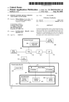
IR-EK2
Infrared Gas Sensor Evaluation Kit
Get started quickly in gas sensor
instrument design using Infrared
Gas Sensors from e2v.
Simply attach the universal power supply, connect
to a PC USB port and plug in an e2v infrared gas
sensor.
The e2v data logging and control software allows
the performance of single gas or twin gas sensors
to be assessed and makes it easy to capture
performance data.
Users can experiment with different settings before
designing their own instrument. Circuit diagram
and parts list supplied.
Gas sensors to be ordered separately
INTRODUCTION
The e2v IR-EK2 Gas Sensor Evaluation Kit will drive the e2v
range of infrared gas sensors and automatically measure
the sensor outputs and calculate gas concentration levels.
Sensors can be controlled automatically via the USB
interface with an easy-to-use control and data logging PC
application provided on CD. Alternatively a terminal program
such as HyperTerminal can be used to send simple
commands to the on-board microcontroller. The user
manual provides a comprehensive set of commands.
The PCB provides sockets for use with e2v 6- and 7-pin
(single gas) or 8-pin (twin gas) infrared gas sensors. For
devices which do not have integrated temperature
monitoring, a temperature sensing IC is provided on the
PCB close to the gas sensor socket positions.
The evaluation kit allows experimentation with different bulb
drive voltages. Reference and active channel gains can also
be adjusted or set to a fixed level. This allows operation with
the full range of e2v infrared gas sensors. Sensors can be
calibrated and then the gas concentration levels monitored.
An expansion connector provides access to four
configurable alarms (open collector), two analog outputs
and four digital inputs. LEDs on the board mimic the status
of each alarm. A JTAG header allows advanced users to
upload their own software to the microcontroller
(MSP430F2616) and make full use of the available
interfaces.
FEATURES
• For use with e2v Infrared Gas Sensors
• Simple control and set-up of sensors
• Operates 6- or 7-pin (single gas) sensor or 8-pin
(twin gas) sensor
• USB interface to a Personal Computer (PC)
• Free PC application software for easy control and
data logging
• Adjustable bulb drive voltage (3.0 V to 5.0 V)
• Adjustable reference and active channel gains
• 16-bit Analog to Digital Conversion (ADC) for
reference and active channels
• Calibrate sensors and monitor gas concentration
levels
• Monitor gas sensor temperature on devices with
integrated thermistor or IC temperature sensor
• PCB mounted temperature sensor IC provided for
devices without integrated temperature monitoring
• Four configurable alarm outputs
• Two configurable analog outputs (12-bit DAC)
• Four digital inputs
• Expansion header for additional applications
• JTAG header for user software upload
• Supplied with universal mains adapter
• Supplied with user manual on CD
• Supplied with gas flow hood
A universal mains adapter is also supplied or the user may
connect a 9 V power supply to the terminal block connector.
Whilst e2v technologies has taken care to ensure the accuracy of the information contained herein it accepts no responsibility for the consequences of any use thereof
and also reserves the right to change the specification of goods without notice. e2v technologies accepts no liability beyond the set out in its standard conditions of sale in
respect of infringement of third party patents arising from the use of tubes or other devices in accordance with information contained herein.
e2v technologies (uk) limited, Waterhouse Lane, Chelmsford, Essex CM1 2QU United Kingdom Telephone: +44 (0)1245 493493 Facsimile: +44 (0)1245 492492
e-mail: [email protected] Internet: www.e2v.com Holding Company: e2v technologies plc
e2v technologies inc. 520 White Plains Road, Suite 450, Tarrytown, NY10591 USA Telephone: (914) 592-6050 Facsimile: (914) 592-5148 e-mail: [email protected]
© e2v technologies (uk) limited 2009
Template: DF764388A-2
A1A-767905 Version 1, October 2009
107155
ELECTRICAL DATA
Universal Mains Adapter
Input Voltage
Input Frequency
Adapters supplied
Output
90 - 264 V ac
50 – 60 Hz
UK, Europe, USA, Australia.
9 V dc
PCB Interfaces
DC Supply Input
SK4
TB1
Input Voltage
Input Protection
User Adjustments
VR0
VR1
VR2
VR3
Ref. channel gain (single/twin gas)
Active Ch.1 gain (single/twin gas)
Active Ch.2 gain (twin gas only)
Lamp drive voltage (3.0 V to 5.0 V)
USB
SK5
Mini-USB type B
MECHANICAL DATA
2.1 x 5.5 mm Socket, centre positive
Terminal Block
9 V ± 10%
Over voltage & current,
Reverse voltage
Dimensions
Mains Adapter
Evaluation Kit PCB
72 x 45 x 29 mm
130 x 55 mm
Gas Sensor Sockets
S1
6-Pin or 7-Pin IR Gas Sensor
S2
8-Pin IR Gas Sensor
Only one device can be fitted at a time.
ENVIRONMENTAL DATA
Signal Monitor
PL3
Mains Adapter
Operating temp: 0 °C to +40 °C
Storage temp: -25 °C to +85 °C
Operating humidity: 10 to 90%
PCBs
Operation and storage from -30 °C
to +75 °C
Sensors
See individual sensor data sheets
8-pin 0.1” Friction Lock (Molex)
1
2
3
4
5
6
7
8
Reference signal monitor
0V
Active 1 signal monitor
0V
Active 2 signal monitor
0V
Bulb control (3V3 logic)
0V
Expansion Connector
PL2
2 x 10-pin 0.1” PCB Header
3V3 Regulated
0V
Input 1 (3V3 logic)
Input 2 (3V3 logic)
Input 3 (3V3 logic)
Input 4 (3V3 logic)
0V
0V
Spare RXD (3V3)
0V
JTAG Connector
PL1
TDO
TDI
TMS
TCK
0V
TRST
Unused
1
3
5
7
9
11
13
15
17
19
2
4
6
8
10
12
14
16
18
20
9 V Unregulated
0V
Output 1 (Open collector)
Output 2 (Open collector)
Output 3 (Open collector)
Output 4 (Open collector)
Analog Out 1 (0 - 2.048 V)
Analog Out 2 (0 - 2.048 V)
Spare TXD (3V3)
Spare
2 x 7-pin 0.1” Box Header
1
3
5
7
9
11
13
2
4
6
8
10
12
14
VCCO
VCCI
Unused
Unused
Unused
Unused
Unused
PERFORMANCE DATA
ADC Resolution
DAC Resolution
Lamp drive frequency
Lamp drive voltage
Channel gain (at 4 Hz)
Channel bandwidth
Temperature sensor IC
accuracy
16-Bit
12-Bit
4 Hz
3.0 V to 5.0 V (adjustable)
Minimum 41
Maximum 400 (approx)
1.5 Hz to 10 Hz (-3dB)
± 2 °C (at 25 °C)
± 3 °C (-25 °C to +85 °C)
RECOMMENDED PC SYSTEM
For Control and Data logging Software:
Processor
Pentium 4/M or equivalent
Operating System
Windows XP or Vista
Screen resolution
1024 x 768 Pixels
RAM
1 GB
Disk Space
1.6 GB
ORDERING INFORMATION
Microcontroller Reset
SW2
Push Button
Indicators
D1 – D4
D5
Operating Temperature Range
Green LEDs (ON = Alarm asserted)
Green LED (Flash = PCB functional)
IR-EK2 - IR Gas Sensor Evaluation Kit containing:
•
Evaluation PCB
•
Universal Mains Adapter
•
USB lead
•
Data Logging Software and User Guide on CD
•
Gas flow hood
Note: Gas Sensors should be ordered separately.
© e2v technologies (uk) limited 2009
Document subject to disclaimer on page 1
A1A-767905 Version 1, page 2