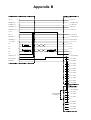
1
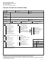
N6081 Series
Operation Manual
e2v technologies
N6081 Series
Operation Manual
# e2v technologies 2004
HBN6081-1 Issue 5, January 2004
186/3591
SAFETY NOTES
The following warnings and precautions are for your
safety and the prevention of injury. Read them carefully
and observe at all times when installing or operating
the N6081. Hazard warning signs, as defined in
BS5378 Safety Signs and Colours are used on the
equipment to highlight any possible hazards.
Mains Supply
(Amplifier Only)
A mains supply disconnection device must be provided to isolate the amplifier from the mains supply
source. Either a socket outlet or a two-pole isolation
switch must be used as the mains supply disconnection device, and it must be easily accessible. The
mains connector must not be used as the mains
supply disconnection device.
ENVIRONMENTAL
*
Do not spray aerosol cleaners directly on to its
surfaces when cleaning.
*
Do not spill water onto the control unit.
*
Do not operate the control unit on an unstable or
unsafe surface.
*
Do not install the control unit in a damp area.
*
Do not expose the control unit to rain or other
sources of water.
*
Ensure that all cables cannot be walked on,
tripped over or damaged by furniture or movable
equipment.
*
Do not place objects inside any of the waveguides.
RF Radiation
Exposure of the human body to microwave radiation
can constitute a hazard (ANSI/IEEE C95-1-1992).
Personnel must be protected from microwave energy
within the RF system.
All RF connectors must be correctly fitted before
operation, so that there is no leakage of RF energy. The
control unit must not be operated unless the RF output
connection is correctly terminated. It is particularly
hazardous to look into open waveguides, coaxial
feeders, or transmitter antennae when the control unit
is operating.
High Temperature
High power RF loads connected to RF systems can be
at temperatures in excess of 80 8C.
Maintenance
Do not remove the covers unless the supply is
disconnected. The supply should not be reconnected
until all of the covers have been refitted.
page 2
HBN6081-1
STANDARDS
COMPLIANCE
This control unit complies with the following requirements. Further details may be provided if necessary.
*
EEC Directive 89/336/EEC Electromagnetic compatibility.
*
EEC Directive 93/97/EEC Satellite earth station
equipment.
*
EEC Directive 73/23/EEC Low voltage directive
e2v technologies’ quality management system is
certificated to the requirements of ISO 9001.
HBN6081-1
CUSTOMER CARE
Stellar 24-Hour Hotline
In the event of a Stellar product fault or urgent
application enquiry, dial the Stellar Hotline telephone
number given below.
At the rear of this manual you will find a blank ‘Fault
Report Form’. Complete this form before ringing the
Hotline; this will help us to respond promptly to your
request.
Telephone: (01245) 355398
International: +44 1245 355398
page 3
CONTENTS
Page
1 Thank You For Buying Stellar
. . . . . . . . . . . . . . . . . . . . . . . .
5
.
.
.
.
.
.
.
.
.
.
.
.
.
.
.
.
.
.
.
.
.
.
.
.
.
.
.
.
.
.
.
.
.
.
.
.
.
.
.
.
.
.
.
.
.
.
.
.
.
.
.
.
.
.
.
.
.
.
.
.
.
.
.
.
.
.
.
.
.
.
.
.
.
.
.
.
.
.
.
.
.
.
.
.
.
.
.
.
.
.
.
.
.
.
.
.
.
.
.
.
.
.
.
.
.
.
.
.
.
.
.
.
.
.
.
.
.
.
.
.
.
.
.
.
.
5
5
5
5
5
.
.
.
.
.
.
.
.
.
.
.
.
.
.
.
.
.
.
.
.
.
.
.
.
.
.
.
.
.
.
.
.
.
.
.
.
.
.
.
.
.
.
.
.
.
.
.
.
.
.
.
.
.
.
.
.
.
.
.
.
.
.
.
.
.
.
.
.
.
.
.
.
.
.
.
.
.
.
.
.
.
.
.
.
.
.
.
.
.
.
.
.
.
.
.
.
.
.
.
.
.
.
.
.
.
.
.
.
.
.
.
.
.
.
.
.
.
.
.
.
.
.
.
.
.
6
6
6
6
6
4 Operation of the Control Unit . .
4.1 Applying The Voltage Supply
4.2 The Amplifier Search Process
4.3 Warm-up . . . . . . . .
4.4 Standby . . . . . . . .
4.5 Transmit . . . . . . . .
4.6 Off . . . . . . . . . . .
4.7 Fault . . . . . . . . . .
.
.
.
.
.
.
.
.
.
.
.
.
.
.
.
.
.
.
.
.
.
.
.
.
.
.
.
.
.
.
.
.
.
.
.
.
.
.
.
.
.
.
.
.
.
.
.
.
.
.
.
.
.
.
.
.
.
.
.
.
.
.
.
.
.
.
.
.
.
.
.
.
.
.
.
.
.
.
.
.
.
.
.
.
.
.
.
.
.
.
.
.
.
.
.
.
.
.
.
.
.
.
.
.
.
.
.
.
.
.
.
.
.
.
.
.
.
.
.
.
.
.
.
.
.
.
.
.
.
.
.
.
.
.
.
.
.
.
.
.
.
.
.
.
.
.
.
.
.
.
.
.
.
.
.
.
.
.
.
.
.
.
.
.
.
.
.
.
.
.
.
.
.
.
.
.
6
6
6
7
7
7
7
7
5 Measurement and Monitor Functions
5.1 Power (watts) . . . . . . .
5.2 Power (dBW) . . . . . . . .
5.3 Helix Current . . . . . . . .
.
.
.
.
.
.
.
.
.
.
.
.
.
.
.
.
.
.
.
.
.
.
.
.
.
.
.
.
.
.
.
.
.
.
.
.
.
.
.
.
.
.
.
.
.
.
.
.
.
.
.
.
.
.
.
.
.
.
.
.
.
.
.
.
.
.
.
.
.
.
.
.
.
.
.
.
.
.
.
.
.
.
.
.
8
8
8
8
6 Gain Setting (Only available on the N6081D) . . . . . . . . . . . . . . . . . .
6.1 Set Gain (result in watts) . . . . . . . . . . . . . . . . . . . . . . . .
6.2 Set Gain (result in dBW) . . . . . . . . . . . . . . . . . . . . . . . .
8
8
8
7 Amplifier Interface . . . . . . . . . . .
7.1 Introduction . . . . . . . . . . .
7.2 Interconnections (see also Appendix A)
7.3 Interconnections for -01 variant (see also
7.4 Termination Resistors . . . . . . .
9
9
9
9
9
2 Care of the Control Unit
2.1 Storage . . . . .
2.2 Handling . . . .
2.3 Unpacking . . . .
2.4 Cleaning . . . .
.
.
.
.
.
3 Installation Considerations
3.1 Mounting . . . . .
3.2 RF Connections . .
3.3 Cooling Considerations
3.4 Interface Connections
. . . .
. . . .
. . . .
Appendix
. . . .
.
.
.
B)
.
.
.
.
.
.
.
.
.
.
.
.
.
.
.
.
.
.
.
.
.
.
.
.
.
.
.
.
.
.
.
.
.
.
.
.
.
.
.
.
.
.
.
.
.
.
.
.
.
.
.
.
.
.
.
.
.
.
.
.
.
.
.
.
.
.
8 Fault Finding . . . . . . . . . . . . . . . . . . . . . . . . . . . . . . . 10
9 Specification . . .
9.1 Electrical . .
9.2 Mechanical .
9.3 Environmental
10 Related Document
page 4
.
.
.
.
.
.
.
.
.
.
.
.
.
.
.
.
.
.
.
.
.
.
.
.
.
.
.
.
.
.
.
.
.
.
.
.
.
.
.
.
.
.
.
.
.
.
.
.
.
.
.
.
.
.
.
.
.
.
.
.
.
.
.
.
.
.
.
.
.
.
.
.
.
.
.
.
.
.
.
.
.
.
.
.
.
.
.
.
.
.
.
.
.
.
.
.
.
.
.
.
.
.
.
.
.
.
.
.
.
.
.
.
10
10
10
10
. . . . . . . . . . . . . . . . . . . . . . . . . . . . 10
HBN6081-1
1 Thank You For
Buying Stellar
2 Care of the
Control Unit
Thank you for buying this Stellar product. This e2v
technologies control unit allows the remote control of
one Stellar amplifier.
Before using your new control unit, we recommend
that you spend a little time reading this manual to
familiarise yourself with its operation and features.
If you have any further questions, or recommendations
on this manual, contact your distributor.
2.1 Storage
*
Store the control unit in its normal horizontal
orientation
*
Storage temperature range is from 740 to +70 8C.
*
Do not use control unit boxes to support the
weight of any other item.
*
Retain the control unit boxes for future use.
*
Avoid severe shocks.
2.2 Handling
The control unit nominally weighs 0.5 kg; no special
handling precautions are required.
2.3 Unpacking
Only install and use the control unit within the specified
environmental limits.
2.4 Cleaning
The control unit is designed to be rack mounted and is
for use in protected environments.
The front panel can be cleaned with a damp cloth. Do
not use detergents or other cleaners without consulting
e2v technologies. The control unit must be disconnected from the Stellar amplifier before cleaning.
HBN6081-1
page 5
3 Installation
Considerations
4 Operation of the
Control Unit
3.1 Mounting
The N6081 is used to control an amplifier from the
following product series:
N61xx
(e.g. N6132D, N6150D)
N63xx
(e.g. N6312, N6318D)
N64xx
(e.g. N6440)
The control unit is designed to be installed in a
standard 19-inch rack mount system and should be
mounted and operated in the normal horizontal
orientation.
Fixing holes of the standard pattern are provided on
the 1U front panel; these provide adequate support for
the unit.
The control unit is designed to be mounted remote
from the amplifier and the RF system.
When designing the installation, a space of approximately 100 mm should be allowed behind the rear
panel of the control unit for the disconnection of and
the bend radius of the interconnection cable.
4.1 Applying The Voltage Supply
The N6081 requires no external power supply as it is
powered by the amplifier via a dedicated line within the
control cabling.
Before connecting the control cabling, the operator
must be satisfied that:
* Safety requirements are complied with (see the
safety notes at the front of this manual)
The amplifier is off.
3.2 RF Connections
*
Always disconnect the interconnection lead from the
control unit to the amplifier before installing or
removing any RF system components.
Connect the control cabling from the amplifier to the
15-way D-type socket on the back of the N6081 and, if
it is safe to do so, apply power to the amplifier.
3.3 Cooling Considerations
4.2 The Amplifier Search Process
The control unit is designed to operate in ambient
temperatures between 0 and +50 8C; it requires no
additional ventilation. Care should be taken when
choosing the location of the control unit, to avoid
external heat sources that may lead to the ambient
temperature exceeding the above limit.
As soon as power is supplied to the amplifier and the
control cabling is connected, the N6081 will initiate the
amplifier search process. This will be apparent as the
following message will be momentarily displayed on
the N6081 display (if the HPA is found quickly, this
message may not be seen):
3.4 Interface Connections
As there are many installation variations, the cabling
between the amplifier and control unit is not provided
as standard. Contact e2v technologies for details of
interface cable accessories.
For details of cable termination instructions including
cable type etc., see section 7.
Search
The N6081 will now search through the 64 available
addresses at a Baud rate of 9600 until communication
is established. This process will continue until an
amplifier is found. When an amplifier is found, a
message will appear on the display, similar to the
following:
Found
HPA @ 40H
This message indicates that communication has been
established with the amplifier whose address is 40H.
This message will be displayed for 2 seconds. It should
be noted that if at any time communication is lost with
the amplifier, this process will be repeated.
The amplifier fan will be rotating at low speed and the
controller "OFF" LED will be lit.
page 6
HBN6081-1
The display will then show the following:
Pwr
4.6 Off
Press the "OFF" key and the Amplifier will return to the
off mode. The display will then show the following:
Pwr
4.3 Warm-up
Press the STBY or XMIT key whilst in the "OFF" state to
begin the TWT cathode warm-up process (180
seconds). In this state power is only applied to the
TWT cathode heater.
WARM-UP LED will be lit.
The Amplifier cooling fans will continue to rotate at full
speed for 120 seconds for TWT cool-down. After the
120 seconds the fans will slow to idle speed.
IT IS RECOMMENDED THAT THE POWER TO THE
AMPLIFIER IS NOT REMOVED BEFORE THE COOLDOWN HAS BEEN COMPLETED.
Display remains unchanged.
4.7 Fault
"OFF" LED will have gone out.
4.4 Standby
If the STBY key had been pressed, from the "OFF"
state, then after 180 seconds the STBY LED will light
and the WARM-UP led will go out.
If at any time a summary fault occurs, the fault
indicator will be lit and the amplifier will leave the
"transmit" state.
Display remains unchanged.
If there are no faults, the amplifier is now ready to go to
the transmit state.
4.5 Transmit
If the XMIT key had been pressed, from the "OFF"
state, then after 180 seconds the XMIT LED will light
and the WARM-UP LED will go out.
The amplifier will operate.
Amplifier fan will rotate at full speed.
Display will now show the output power in watts.
Pwr
150 W
If the XMIT key had been pressed, from the STBY
state, then the amplifier will operate immediately.
HBN6081-1
page 7
5 Measurement and 6 Gain Setting
Monitor Functions
(Only available
on the N6081D)
5.1 Power (watts)
Once the N6081 has found an amplifier, its display will
show the amplifier’s forward power in watts.
The Amplifier must be fitted with a digital attenuator (DEVA) for this facility.
6.1 Set Gain (result in watts)
5.2 Power (dBW)
This feature can be selected by pressing the function
select key once. This will display the amplifier’s forward
power in dBW (decibel watts). The reading is only valid
if the forward power is greater than 0 W, otherwise the
reading will be blanked.
5.3 Helix Current
This feature can be selected by pressing the function
select button once more. This will display the helix
current of the TWT in mA.
Note: These functions are only available whilst the
amplifier is in ‘Transmit’ state.
This feature can be selected by pressing the function
select button once more. This will allow the digital
attenuator to be set on the amplifier. This is achieved
by turning the gain select knob on the front of the
N6081D, which will result in a change of forward power
from the amplifier, which will be displayed on the
screen in watts.
Ensure the gain knob is fully anti-clockwise for
lowest power setting
6.2 Set Gain (result in dBW)
This feature can be selected by pressing the function
select button once more. This is in essence the same
feature as above but the amplifier’s forward power is
displayed in dBW. Pressing the function select button
again will result in the display returning to ‘Power
(watts)’ setting and further presses will scroll through
the functions as described.
Ensure the gain knob is fully anti-clockwise for
lowest power setting
Note: These functions are only available whilst the
amplifier is in ‘Transmit’ state.
page 8
HBN6081-1
7 Amplifier
Interface
7.1 Introduction
Connection to the Stellar Amplifier is made via a 15way D-type socket for the N6081X series or a 26-way
D-type plug for the N6081X-01 series.
The control unit obtains its power supply (15 V,
100 mA) from the Stellar amplifier via this D-type
connection. The D-type back shell and control connector back shell must have a 3608 electrical connection to the cable screen to prevent Radio Frequency
Interference (RFI) from adversely affecting the operation of the product.
A screened multicore cable must be used for the
interconnection.
To avoid the risk of crosstalk on the "data communications" lines, they must be twisted pairs.
The N6081X-01 series also has a 9-way D-type socket
to enable connection to the RF INHIBIT and INV RF
INHIBIT lines.
7.2 Interconnections (see also Appendix A)
41-way amplifier
connector
A . . .
B . . .
C . . .
D . . .
E . . .
H, P, R, p . .
J . . .
K . . .
L . . .
U . . .
b . . .
c . . .
d . . .
e . . .
Notes: Cable for
Cable for
pair.
HBN6081-1
.
.
.
.
.
.
.
.
.
.
.
.
.
.
b
d
15-way D-type
connector
. . . . 2
. . . . 4
. . . . 3
. . . . 5
. . . . 6
. . . . 14
. . . . 7
. . . . 8
. . . . 9
. . . . 1
. . . . 10
. . . . 11
. . . . 13
. . . . 12
and c must be a twisted pair.
and e must also be a twisted
7.3 Interconnections for -01 variant (see also
Appendix B)
41-way amplifier
connector
A . . .
B . . .
C . . .
D . . .
E . . .
G . . .
H . . .
J . . .
K . . .
L . . .
P, R, p . .
U . . .
b . . .
c . . .
d . . .
e . . .
Notes: Cable for
Cable for
pair.
.
.
.
.
.
.
.
.
.
.
.
.
.
.
.
.
b
d
26-way high density
D-type socket
. . . . 8
. . . . 6
. . . . 7
. . . . 5
. . . . 4
. . . . 10
. . . . 1
. . . . 19
. . . . 2
. . . . 25
. . . . 20
. . . . 9
. . . . 24
. . . . 23
. . . . 21
. . . . 22
and c must be a twisted pair.
and e must also be a twisted
9-way connector
1 . . . . .
2 . . . . .
3 . . . . .
4 . . . . .
5 . . . . .
6 . . . . .
7 . . . . .
8 . . . . .
9 . . . . .
Note: To enable RF,
function
INV RF INHIBIT
. . not used
. . not used
. . not used
. . . 0V
. RF INHIBIT
. . not used
. . not used
. . not used
link pins 1 and 5.
7.4 Termination Resistors
A 120 O 1/4 W resistor is to be fitted in the D-type
back shell between pins 12 and 13 (pins 21 and 22 for
the -01 variant).
A 120 O 1/4 W resistor is to be fitted in the 41-way
connector back shell between pins b and c and
another 120 O 1/4 W resistor between d and e.
page 9
8 Fault Finding
9 Specification
If the control unit does not work correctly, consult the
following table before contacting either the Stellar 24hour Hotline (see ‘Customer Care’, page 3) or your
distributor for further assistance.
Consult the relevant amplifier operations manual for
descriptions of amplifier fault messages given on the
front panel displays.
9.1 Electrical
Fault experienced
Possible cause
No communication
with the amplifier
Interconnecting cable damaged
or unconnected
Amplifier not powered
Prime power:
voltage . . . . . . . . . . . . . . . 15 V
current . . . . . . . . . . . . . . 100 mA
9.2 Mechanical
Dimensions (19-inch rack):
width . . . . . . . . . 483 mm (19 inches)
height . . . . . . . 1U, 44 mm (1.73 inches)
depth . . . . . . . . . . 50 mm (2 inches)
depth with allowance for connectors
and bend radius of cable . . 150 mm (6 inches)
Weight (nominal) . . . . . .
0.5 kg (1.1 pounds)
9.3 Environmental
For operation outside these parameters, refer to e2v
technologies for guidance.
Operating temperature . . . . . .
0 to +50 8C
Storage temperature . . . . . . 740 to +70 8C
Vibration . . . .
MIL-STD-810E; common carrier
and field transportation
Shock . . . . . . IEC Publication 68-2-27 Part 2
Test Ea 25 g for 11 ms, half-sine
Electromagnetic compatibility . . .
EMC Directive
89/336/EEC
Safety . . . . . . . . .
Low Voltage Directive
73/23/EEC BS EN 60950
10 Related
Document
*
page 10
Data Sheet (A1A-N6081 series).
HBN6081-1
Appendix A
41-way Stellar
Amplifier connector
15-way D-type
Controller connector
A
2
B
4
C
3
D
5
E
6
H
14
J
7
K
8
L
9
P
R
U
1
b
10
120R 1/4W
c
11
twisted pairs
d
13
120R 1/4W
e
p
120R 1/4W
12
Appendix B
26-WAY HIGH DENSITY
D PLUG (PL1)
TO N631X 41-WAY CONTROL CONNECTOR
OFF S/O
A
8
OFF S/O
WARM UP S/O
B
6
WARM UP LED
STANDBY S/O
C
7
STDBY LED
TRANSMIT S/O
D
5
XMIT LED
SUM. FAULT S/O E
4
FAULT S/O
0 V (B)
P
OFF C/I
J
19 OFF SWITCH
STANDBY C/I
K
2
TRANSMIT C/I
L
25 XMIT SWITCH
+15 V (AUX)
U
9
TX+
b
STDBY SWITCH
Vin (+15 V)
24 RX+
120 R
TX7
c
RX+
d
23 RX7
21 TX+
120 R
120 R
RX7
e
22 TX7
SG
p
20 0 V
INTERLOCK I/P
R
1
INV RF INHIBIT
INV RF INHIBIT
H
3
NOT USED
RF INHIBIT
G
10 RF INHIBIT
11 NOT USED
12 NOT USED
13 NOT USED
14 NOT USED
15 NOT USED
16 NOT USED
17 NOT USED
18 NOT USED
26 NOT USED
9-WAY
D SOCKET (SK1)
LINK REQUIRED
TO ENABLE RF
1
INV RF INHIBIT
2
NOT USED
3
NOT USED
4
NOT USED
5
0V
6
RF INHIBIT
7
NOT USED
8
NOT USED
9
NOT USED
E2V Technologies Limited,
106 Waterhouse Lane, Chelmsford,
Essex CM1 2QU, UK.
Tel. or Fax: +44 (0) 1245 355398
STELLAR HOTLINE FAULT REPORT FORM
Date:
Call Time:
Tel. No.:
Name:
Fax No.:
Organisation:
Location:
Country:
Product Type:
Category:
Serial No.:
A. 1 Hour
B. Next Day
C. Next Working Day
Nature Of Problem Or Request (Check appropriate boxes or refer to topic numbers):
Unit Is Defective:
1
2
3
4
5
6
7
8
9
10
Fuse has blown
Circuit breaker trips
No fans operating
No display
No indicators
No cathode warm-up
No standby mode
No transmit mode
No output power
Other (see comments)
Unit Is Malfunctioning:
11
12
13
14
15
16
17
18
Low output power
High input power
High reflected power
High helix current
Unit trips
Unit trips repeatedly
Unit trips and shuts down
Other (see comments)
19
20
21
22
23
24
25
26
Bad airflow
Helix overcurrent
Excess reflected power
PSU overcurrent
PSU too hot
RF load too hot
LV PSU fault
Bad HV rail
Difficulties With Control Panel Or Remote Interface:
27
28
29
30
Set-up
Helix current meter
Power meters
Low power alarm
31
32
33
34
Applications Enquiries:
35
36
37
38
39
40
Prime power
Front panel operation
Cooling / ducting
RF input circuit
RF output circuit
Other (see comments)
Hour counters
IEEE488 / RS422 / RS485
User port
Other (see comments)
Commercial Enquiries:
41
42
43
44
Data sheets
Applications sheets
Sales contact
Other (see comments)
For E2V Technologies
use only
CAT:
ENG:
TIME:
SIG:
DR No:
Comments And Observations:
Please complete this form prior to using the E2V Technologies ‘STELLAR HOTLINE’; it will help us respond
promptly to your request. Be aware that telephone conversations may be recorded.
The completed form may also be faxed or mailed to the address above and should be sent with any unit returned
to E2V Technologies for repair.
9711A-5
e2v technologies
UK:
e2v technologies limited
Waterhouse Lane Chelmsford
Essex CM1 2QU
USA:
e2v technologies inc.
4 Westchester Plaza
Elmsford NY 10523-1482
Telephone: +44 (0)1245 493493
Facsimile: +44 (0) 1245 492492
Telephone: (914) 592-6050
Facsimile: (914) 592-5148
France:
e2v technologies sas
Bat. 16 BUROSPACE
F-91572 BIÈVRES Cedex
Canada:
e2v technologies inc.
7956 Torbram Road Suite No. 208
Brampton Ontario L6T 5A2
Telephone: (331) 6019 5500
Facsimile: (331) 6019 5529
Telephone: (905) 789-3840
Facsimile: (905) 789-3847
Holding Company:
e2v holdings limited
Internet: www.e2vtechnologies.com