1
OBJ_BUCH-1128-002.book Page 53 Tuesday, July 13, 2010 11:27 AM
English | 53
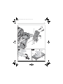
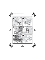
Aligning the Angle Indicator (Horizontally)
(see figure W)
– Bring the power tool into the working position.
– Turn the saw table 16 to the 0° detent 15.
The lever 13 must be felt to engage in the detent.
Checking:
The angle indicator 71 must be in alignment
with the 0° mark of the scale 38.
Adjusting:
– Loosen the fastening screw of the angle indicator with the supplied Phillips screwdriver
33 and align the angle indicator alongside the
0° mark.
– Retighten the screw again.
Aligning the Fence
– Bring the machine into the transport position.
– Turn the saw table 16 to the 0° detent 15.
The lever 13 must be felt to engage in the detent.
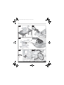
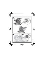
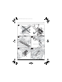
Checking: (see figure X1)
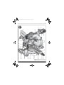
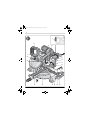
Transport (see figure Y)
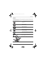
Before transporting the power tool, the following steps must be carried out:
– Loosen the locking screw 29 if tightened.
Pull the tool arm completely to the front and
tighten the locking screw again.
– Bring the machine into the transport position.
– Remove all accessories that cannot be
mounted firmly to the power tool.
If possible, place unused saw blades in an
enclosed container for transport.
– Carry the power tool by the transport handles 28 and 2 or via the recessed grips 74 on
the side of the saw table.
f The power tool should always be carried by
two persons in order to avoid back injuries.
f When transporting the power tool, use only
the transport devices and never use the
protective devices.
Maintenance and Service
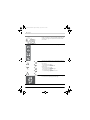
– Set an angle gauge to 90° and place it on the
saw table 16 between the fence 18 and the
saw blade 7.
Maintenance and Cleaning
The leg of the angle gauge must be flush with
the fence over the complete length.
If the machine should fail despite the care taken
in manufacturing and testing procedures, repair
should be carried out by an after-sales service
centre for Bosch power tools.
Adjusting: (see figure X2)
– Loosen the locking screws 20 on bothe sides
of the fence extensions 19.
Loosen the setting screws 72 with the supplied Allen key 33 (4 mm).
– Remove the fence extensions.
– Loosen all Allen screws 73 with the supplied
socket spanner 33 (14 mm).
– Turn the fence 18 until the angle gauge is
flush over the complete length.
– Retighten the Allen screws 73.
– Retighten the fence extensions. Tighten the
setting screws 72 only to the extent, that the
fence extensions can be moved easily.
f Before any work on the machine itself, pull
the mains plug.
In all correspondence and spare parts order,
please always include the 10-digit article
number given on the type plate of the machine.
Cleaning
For safe and proper working, always keep the
power tool and its ventilation slots clean.
The retracting blade guard must always be able
to move freely and retract automatically. Therefore, always keep the area around the retracting
blade guard clean.
Remove dust and chips after each working procedure by blowing out with compressed air or
with a brush.
Clean the roller 9 regularly.
Bosch Power Tools
1 609 929 X04 | (13/7/10)