1
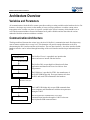
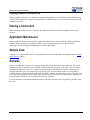
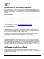
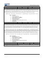
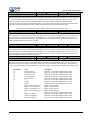
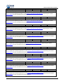
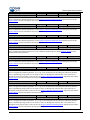
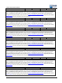
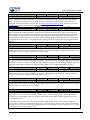
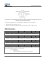
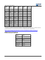
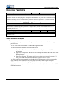
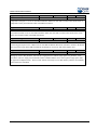
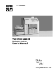
Engineering Note Topic: NeoFox Communication Interfaces Products Affected: NeoFox Date Issued: 04/18/2011 Updated: November 2012 Description NeoFox is a dynamic measurement system that has been designed to work with a variety of optical probes to measure oxygen in a variety of conditions. To support the various probe technologies and the broad spectrum of applications that employ the system, the NeoFox measurement system itself has a multitude of configuration options that must be considered by developers and advanced scientists. This document will discuss the process by which NeoFox parameters are written to and read from the device. It assumes that the reader already has a basic understanding of how the NeoFox measures oxygen and a basic understanding of general programming concepts. Topics addressed in this Engineering Note include the following: Topic Description Architecture Overview NeoFox Serial Interface DLL Interface NeoFox DLL Function Reference Driver Interface and Hardware Interface NeoFox Variable Reference Table Additional Firmware Controls in FW Version 2.25 013-20000-010-04-201211 Page 1 2 3 5 7 11 11 24 1 NeoFox Communication Interfaces Architecture Overview Variables and Parameters All communication with the NeoFox centers upon either reading or setting variables on the hardware device. For instance, a developer may want to set the number of scans to average parameter or read the current sensor temperature value. In either case, there is a specific variable in the system’s memory which should be set or read. This document includes reference information for all public variables and also describes the various methods with which to interact with these variables. Communication Architecture The diagram below illustrates the various layers involved in NeoFox’s communication stack. Developers may want to interact with the device at any level. This document will provide enough information to do so by documenting the DLL interface and the serial interface. The two other interfaces – the driver interface and the hardware interface can be inferred through knowledge of the serial interface and developer information from FTDI. Software NeoFox Viewer The NeoFox Viewer is a graphical user interface that allows end users to interact with the NeoFox DLL Interface NeoFox DLL The NeoFox DLL accepts high level function calls from applications and abstracts the lower level drivers from programmers. Driver Interface USB Driver The USB driver is provided by FTDI - the manufacturer of the UART-USB Bridge chip. It accepts function calls from the DLL and sends USB commands to the hardware. Hardware Interface UART-USB Bridge The UART-USB bridge chip accepts USB commands from a host computer and communicates with the microprocessor through a UART. Serial Interface Microprocessor The microprocessor communicates via a serial communications interface through its UART. It does not natively handle USB communications. Hardware 2 013-20000-010-04-201211 NeoFox Communication Interfaces NeoFox Serial Interface Overview The NeoFox serial protocol can be used for a number of purposes. Most significantly, future versions of the NeoFox hardware may have an RS232 serial output that will directly expose this protocol. Additionally, knowledge of the serial protocol can be used in conjunction with knowledge of the FTDI USB protocol to create custom USB drivers for the NeoFox, which are necessary for embedded host applications or non-windows based PC host applications. From the perspective of the embedded microcontroller, the serial protocol essentially has only two functions: to read and write parameters and variables. Settings Setting Value Baud Rate: 750,000 baud (default) Stop Bits: 1 Parity: None Flow Control: None Byte Order: Little endian Integer Size: 4 bytes Float Size: 4 bytes The following settings represent the default settings of the UART when used in through the USB interface. The default settings for the UART when it is communicating through the RS232 interface are listed in RS232 Default Settings. Writing Data to the NeoFox All of the writable parameters on the NeoFox fall into two categories: floating point types and integer types (including char, short, etc). Regardless of type, all parameters accept the same command frame structure to set their values. This structure is documented below. There are two fields in this command that require detailed explanation. First, bytes 8 through 11 hold the ParamType field. This field contains a code that indicates which parameter is to be set by the command. A list of parameters and codes is available at the end of this document. The ParamValue field (bytes 12 through 15) contains the actual value that is to be set by the command. This field does not have an explicit type listed in the table below. The type is determined by the type of the parameter value (also listed in the table at the end of this document). If the parameter is an integer type (short, char, long, etc), then these four bytes are interpreted as a 4 byte signed integer (little endian) and then cast to the actual type. If the parameter is a floating point type, then the four bytes are explicitly interpreted as a little endian floating point value. 013-20000-010-04-201211 3 NeoFox Communication Interfaces Addr Type Name Description 0 uchar Stx Start of transmission character. Set to 0x03. 1 uchar PacketType Set to 0xC8 2 ushort FrameSize Set to 20 (0x14). 4 ulong CmdNumber Reserved. Set to 0. 8 ulong ParamType Type code for the parameter that is to be set. 12 n/a ParamValue Value for the parameter to be set. Can be a float or integer type. 16 uchar Reserved1 Reserved. Set to 0. 17 uchar Reserved2 Reserved. Set to 0. 18 uchar Checksum Set to the aggregate sum of all previous bytes modulus 256. 19 uchar Eof End of transmission character. Set to 0x04. Reading Data from the NeoFox The NeoFox streams a “data dump” of all its publicly exposed parameters after each sample. This occurs approximately once every tenth of a second. The location of each particular value within this stream is given in the table at the end of this document. The data stream is structured as follows. Addr Type Name Description 0 uchar Stx Start of transmission character. Set to 0x03. 1 uchar PacketType Set to 0xDC 2 ushort FrameSize Set to 5036 (0x13AC) 4 uchar FrameCount Number of frames uploaded since the device powered on. This rolls over after 255. It can be used to determine whether any frames have been missed. 5 uchar ProtocolRev The value of the Data Copy Type parameter. The structure is a "type 1" structure (the default communication structure for NeoFox). Therefore, this value will be 0x01. See Data Copy Type for more information on alternative data structures. 6 uchar Reserved1 Reserved. Do not depend on this value. 7 uchar Reserved2 Reserved. Do not depend on this value. 8 … 927 n/a Data Parameters are stored in this region of the structure. See the table at the end of this document for variable-specific documentation and addresses. 928 … 2979 struct SensorBlue Blue sensor waveform raw data. This contains the data that can be seen in the “sensor waveform window” in the NeoFox Viewer. 2980 struct SensorRed Red sensor waveform raw data. This contains the data that can 4 013-20000-010-04-201211 NeoFox Communication Interfaces Addr Type Name … 5031 Description be seen in the “sensor waveform window” in the NeoFox Viewer. 5032 uchar Reserved3 Reserved. Do not depend on this value. 5033 uchar Reserved4 Reserved. Do not depend on this value. 5034 uchar Checksum Set to the aggregate sum of all previous bytes modulus 256. 5035 uchar Eof End of transmission character. Set to 0x04 DLL Interface The NeoFox DLL can be used by developers without the need to understand the USB or serial interface layers. The DLL itself abstracts these layers and provides an interface of high-level function calls. This DLL interface can be easily used with almost any programming language: Labview, C, C++, Visual Basic, Java, or even VBA for excel. The DLL enables the user to perform any of the following four common actions: It allows users to open a connection to a NeoFox device, read values from the device, set parameters on the device, and close the connection to the device. The functions which enable these actions are described below. Opening a Connection There are two steps to creating a connection to a NeoFox. First, the user must call the DevicePerformDiscovery function, which internally creates an index list of all unopened NeoFox units that are connected to the computer. In addition to creating an indexed list, this function will also inform the user of the number of unopened NeoFox units that are connected. Once the list has been created, the user must call the DeviceOpenChannel for each NeoFox unit for which a connection is to be established. The DeviceOpenChannel function takes an index as its parameter and it opens the particular NeoFox unit that corresponds to that index in the list that was generated by the DevicePerformDiscovery function. However, since DevicePerformDiscovery does not provide any information about the units that it discovers, the indices are essentially arbitrary and in order to select any particular NeoFox unit, the user will basically need to open all available NeoFox units and they query them each individually to determine its name. It can then close connections to the units that it does not need. Reading Data from the NeoFox Reading variables from the device is accomplished through either of two functions: DeviceGetParameter or DeviceGetParameterFloat. The determination of which function to use is based on the type of the variable that is to be read. Use DeviceGetParameterFloat for floating point type parameters and DeviceGetParameter for any other type of parameter. It is important to note that the NeoFox is a discrete sampling system. New samples are only refreshed from the hardware device approximately once every tenth of a second, and operating system latency may result in even lower throughput. Therefore, developers may find it useful to poll the Millisecond Count variable to evaluate whether or not information in the DLL has been refreshed since the last time that information was read. 013-20000-010-04-201211 5 NeoFox Communication Interfaces Writing Data to the NeoFox Writing variables to the device is similarly accomplished through either of two functions: DeviceSetParameter or DeviceSetParameterFloat. Again, the determination of which function to use will be based on the type of the data that is to be sent. Closing a Connection When interaction with the device is complete, the connection should be closed by calling the DeviceClose function. Application Maintenance Before calling any functions from the DLL, applications should make a call to the DLL’s ApplicationStartup function, which will begin a new thread in which it can run its background processes. Before exiting, applications should call ApplicationShutdown to terminate this thread. Sample Code A sample C++ program (MS Visual C++) that demonstrates how to use the device is available from the Ocean Optics Sensors website. Remarks There is one additional issue that some early developers have faced which bears some discussion. The szText parameters, which are defined as type LPTSTR, are implemented as type char* in the DLL. There is a known issue with the Microsoft Visual C++ compiler in which sometimes the compiler has trouble casting between LPTSTR and char* types. One simple way to resolve this issue is to not include windows.h, which defines LPTSTR, and use a typedef instead (typedef char* LPTSTR). Another, more advisable, way to correct this issue is to set the project properties to use a multi-byte character set. This can be done by adjusting the “character set” project property at Properties Configuration Properties General. It is also important to note that the maximum number of NeoFox units that can be supported by the DLL at one time is 8. 6 013-20000-010-04-201211 NeoFox Communication Interfaces NeoFox DLL Function Reference int DeviceSetParameter(int hDevice, int ParamType, int dValue) Description Sets an integer parameter on the NeoFox. Parameters int hDevice Handle to an open NeoFox device. int ParamType Unique code for the parameter which is to be set. int dValue Value to be written to the parameter. Return Value Number of bytes written to the hardware device in order to issue the set parameter command message. This includes the command packet overhead in addition to the ParamType code and the dValue payload. At the time of this writing, the size of this transaction is 20 bytes. Remarks Although the dValue parameter is a 4 byte integer, this function should also be used to set short and char type parameters as well. int DeviceSetParameterFloat(int hDevice, int ParamType, float fValue) Description Sets a floating point parameter on the NeoFox. Parameters int hDevice Handle to an open NeoFox device. int ParamType Unique code for the parameter which is to be set. float fValue Value to be written to the parameter. Return Value Number of bytes written to the hardware device in order to issue the set parameter command message. This includes the command packet overhead in addition to the ParamType code and the dValue payload. At the time of this writing, the size of this transaction is 20 bytes. int DeviceGetParameter(int hDevice, int ParamType, LPTSTR szText) Description Reads an integer type parameter from the NeoFox device. 013-20000-010-04-201211 7 NeoFox Communication Interfaces Parameters int hDevice Handle to an open NeoFox device int ParamType Unique code for the parameter which is to be read. LPTSTR szText A character buffer (char*). Be sure to pass this parameter a pointer to an initialized buffer of at least 50 bytes. Return Value The function returns an int that represents the value that has been queried from the device. In some cases, it will also populate the szText buffer with a textual representation of the integer value. Remarks Although this function returns a 4 byte integer value, it should also be used to query the values of short and char type parameters. It is also important to note that although the function will sometimes populate the szText buffer, users are advised not to use this value unless the szText parameter is explicitly discussed in a particular variable’s information (from the variable table at the end of this document). float DeviceGetParameterFloat(int hDevice, int ParamType, LPTSTR szText) Description Reads a floating point type parameter from the NeoFox device. Parameters int hDevice Handle to an open NeoFox device int ParamType Unique code for the parameter which is to be read. LPTSTR szText A character buffer (char*). Be sure to pass this parameter a pointer to an initialized buffer of at least 50 bytes. Return Value The function returns a float that represents the value that has been queried from the device. In some cases, it will also populate the szText buffer with a textual representation of the integer value. Remarks Although this function returns a 4 byte integer value, it should also be used to query the values of short and char type parameters. It is also important to note that although the function will sometimes populate the szText buffer, users are advised not to depend on this information, which is not explicitly supported. int ApplicationStartup(int hInstance) Description This function starts a thread for the DLL. Parameters int 8 hInstance Pass NULL to this parameter. 013-20000-010-04-201211 NeoFox Communication Interfaces Return Value This function always returns a value of 1. Remarks This function should be called at the beginning of any user program, before any other DLL functions are called. int DevicePerformDiscovery(int vendorID, int productID, int ShowGUI) Description This function instructs the DLL to create an indexed list of all NeoFox devices that are connected to the system via USB but have not been opened already. Parameters int vendorID Vendor ID for the NeoFox product. The value is 0x2457. int productID Product ID for the NeoFox product. The value is 0x3000. int ShowGUI This parameter is reserved. Pass it a value of 0. Return Value This function returns the number of NeoFox devices that have been connected to the system via USB, but have not yet been opened with the DeviceOpenChannel function. Remarks This function must be called before a call to DeviceOpenChannel. It creates internally an indexed list of unopened NeoFox devices. The DeviceOpenChannel function will accept one of the indices from that list as a parameter to determine which device will be opened. It is important to note that once the DeviceOpenChannel function has been called to open a connection to any of the NeoFoxes in the list, the remaining indices remain valid until the next call to DevicePerformDiscovery. When DevicePerformDiscovery is called after DeviceOpenChannel has been called, it will re-index its list without including the newly opened NeoFox. Subsequent calls to DeviceOpenChannel will need to use the new indices as appropriate. int DeviceOpenChannel(int Select, int SubChannel, int ShowGUI) Description Opens a NeoFox device and returns a handle to that device. Parameters int Select Index of the unopened NeoFox which is to be opened. See remarks for more information about this parameter. int SubChannel This parameter is reserved. Pass it a value of 0. int ShowGUI This parameter is reserved. Pass it a value of 0. Return Value Returns an integer handle to the NeoFox device that has been opened by the function. A value of 0 or -1 indicates that the function has failed to open the NeoFox device properly. Handle values begin at 10000 and increment upwards as new NeoFox devices are opened. 013-20000-010-04-201211 9 NeoFox Communication Interfaces Remarks This function should be called immediately after the DevicePerformDiscovery function has been called. The DevicePerformDiscovery function will create an indexed list of all NeoFoxes that are connected to the computer via USB and the DevicePerformDiscovery function will then instruct it to open a connection to one of those devices by passing in a specific index from the list and receiving a handle to the connection. One common question is how the appropriate index value for the Select parameter should be determined. For those users who can assume that only one NeoFox device will be connected to the system, the simple answer is to pass this parameter a value of 0. Some users may need to account for the scenario where multiple NeoFox units are present in the system, but only one particular unit is to be opened. In this case, the suggested approach is to open all available NeoFox units and query their names directly, then close connections to all but the target device. Note that the number of unopened devices attached to the system at any time is returned by the DevicePerformDiscovery function. int ApplicationShutdown() Description Terminates the DLL’s thread and performs cleanup operations. Parameters None Return Value Returns 1 if successful. int DeviceClose(int hDevice) Description Terminates a connection to a particular device. Parameters int hDevice Handle to an open NeoFox device. Return Value Returns 1 if successful. 10 013-20000-010-04-201211 NeoFox Communication Interfaces Driver Interface and Hardware Interface Some developers may wish to access the NeoFox device at the USB driver level or the hardware level. To do this, developers will need to combine the information from the serial interface description in this document with information from the USB-UART bridge chip manufacturer, FTDI. The chip that is used on the NeoFox is the FT232RQ. Driver Interface An example of an application that would use the driver interface level would be an application that needs to run on Linux or Macintosh computers – systems for which a USB driver is already available from FTDI but support for the NeoFox DLL is not. Driver information is available from FTDI at the link below. This documentation will explain how to use function calls to the USB driver to exercise the USB-UART bridge’s UART. In other words, it will explain how to write bytes to the UART and read bytes from the UART. In this way, the developer can use the serial interface information from this document to interact with the microcontroller. The driver documentation is located here: http://www.ftdichip.com/Drivers/D2XX.htm . Hardware Interface An example of an application that would use the hardware interface level would be a system that uses an embedded microcontroller’s USB “On the Go” host feature to host the NeoFox. In this case, the developer would need to write custom USB drivers for his device. To do this, he would need to understand the way that the NeoFox hardware communicates over USB – the hardware interface. Hardware interface documentation is also available from FTDI. This documentation explains how USB commands can be sent to the device to exercise the UART. Again, this information can be combined with knowledge of the serial interface to produce a compete interface description of the device. Unfortunately, the hardware interface information from FTDI is not publicly available. However, it can be obtained from FTDI by entering into an NDA with them. To obtain the USB communication documentation, send an email to [email protected]. One important note for developers who will interface directly with the USB layer is that in order to begin interacting with the device, the first step in communications will be to set up the USB chip’s UART settings. These settings must match the NeoFox processor’s UART settings. Specifically, the developer will need to set the baud rate, parity, data bits, and stop bits. Information on how to set these settings is provided in the OEM documentation from the chip vendor, FTDI. The processor’s settings are listed in a table in the NeoFox Serial Interface section of this document. NeoFox Variable Reference Table The following table lists all publicly exposed parameters and variables that are available to the developer. Because the DLL interface and serial interface both operate on the same variable space, the information contains information that is relevant to both. The table information is organized as follows: 013-20000-010-04-201211 11 NeoFox Communication Interfaces Parameter Name DLL ParamType Constant • • • • • • • • Type Set Function Range Param Type Get Function Address V1 Parameter Name – The name of the parameter, as you will find it throughout this document and others that describe the NeoFox. Type – The data type of the parameter. Range – The valid range of values for the parameter or value. For writable parameters, developers should ensure that the values written are within the acceptable range. For readable parameters, the developer should consider values that are outside of the given range invalid. Param Type – The parameter code, which is used in the both the DLL interface and the serial interface. In the DLL, this value is passed to DeviceGetParameter as the ParamType argument in order to read a value and it is passed to DeviceSetParameter as the ParamType argument in order to set a value. In the serial protocol, it serves as the ParamType code within a command message to set a parameter. Address V1 -- The address for the parameter within the serial interface’s readback “data dump”. This address is only valid for protocol version 1 (ie: the ProtocolRev field = 1). Future versions of the protocol may have parameters located at different addresses. DLL ParamType Constant – The constant which has been defined in the NeoFoxDLL.h file to represent the ParamType code for this parameter. Set Function – The DLL function to call in order to set the parameter. Get Function – The DLL function to call in order to read the parameter. Percent Oxygen NEOFOX_OXYGEN Float Read-Only 0≤X 20 740 DeviceGetParameterFloat The Percent Oxygen parameter is the partial pressure of oxygen, expressed as percent of 1 ATM. Note that it does not actually represent the concentration of oxygen relative to ambient pressure. The Percent Oxygen option produced by the Converted Oxygen parameter can be used to represent the concentration of ambient pressure. Converted Oxygen NEOFOX_OXYGEN_CONVERTED Float Read-Only 0≤X 23 864 DeviceGetParameterFloat Converted oxygen is the current oxygen reading, converted from percent of 1ATM to an alternate unit. The Oxygen Units parameter documentation has more information about which units are available. Uint Enum Oxygen Units NEOFOX_OXYGEN_UNITS DeviceSetParameter Sets the unit type for the Converted Oxygen parameter. The Value 0 Units Percent of 1 ATM Description Gaseous – Partial Pressure 1 4 7 8 Parts per Million Torr Micro Mole per Liter Percent Concentration Dissolved – Concentration Gaseous – Partial Pressure Dissolved – Concentration Gaseous – Concentration 152 488 DeviceGetParameter DLL Constant NEOFOX_O2_UNITS_PERCENT_ PARTIAL_PRESSURE NEOFOX_O2_UNITS_DO_PPM NEOFOX_O2_UNITS_TORR NEOFOX_O2_UNITS_UMOL_L NEOFOX_O2_UNITS_PERCENT_ CONCENTRATION Ambient pressure is measured in the electronics unit itself. Therefore, the percent oxygen concentration value will be incorrect if the ambient pressure of the electronics unit and the ambient pressure of the probe's environment are not the same. See NeoFox Calibration and Measurement for more information about the converted oxygen parameters. 12 013-20000-010-04-201211 NeoFox Communication Interfaces Float Read-Only Tau NEOFOX_TAU -1 < X 19 736 DeviceGetParameterFloat Tau is an intermediate value, expressed in microseconds, that is calculated in the conversion from phase to oxygen. It should be used for diagnostic purposes only. Temperature Source NEOFOX_CAL_TEMP_SOURCE Uint Enum DeviceSetParameter 165 316 DeviceGetParameter Temperature Source determines which source should be used for temperature measurement during calibration. When the value is 0 (no temperature source), measurements which are dependant upon temperature such as dissolved O2 readings and multipoint calibrations should return -1. Value 0 1 2 Description No temperature source is used. The external temperature sensor is used. The “Fixed Temperature” is used. Fixed Temperature NEOFOX_CAL_DEFAULT_TEMP DLL Constant NEOFOX_TEMP_SOURCE_NONE NEOFOX_TEMP_SOURCE_SENSOR NEOFOX_TEMP_SOURCE_FIXED Float X < 200 DeviceSetParameterFloat 164 304 DeviceGetParameterFloat Fixed Temperature is a user defined fixed temperature that can be used instead of the external temperature sensor in the conversion process. Int Read-Only Sensor Temperature NEOFOX_TEMPERATURE X < 200*216 10 796 DeviceGetParameter Sensor Temperature is the temperature value of the sensor in degrees Celsius. It is important to note that this parameter is stored in a fixed point representation in the NeoFox’s variable space. Therefore, in order to use this value as a floating point number, the raw value must be converted from fixed point (integer type) to floating point with the formula below. Floating Point Temperature Value (in degrees Celsius) = Raw Integer Temperature Value / 216 Number of Averages NEOFOX_PHASE_AVG_CNT_BLUE Uint 1 ≤ X ≤ 300 DeviceSetParameter 129 88 DeviceGetParameter Number of Averages is the number of oxygen samples that are averaged together on the NeoFox to produce the current value of the Percent Oxygen and Converted Oxygen values. This is a running average. Uint Enum DeviceSetParameter Flashing On/Off NEOFOX_LED_CONTROL 121 528 DeviceGetParameter The Flashing On/Off parameter enables and disables sampling. When this parameter is set to off, the LEDs will not flash. Tau and oxygen measurements will be 0 or -1 and should be considered invalid. Value 0 3 013-20000-010-04-201211 Description Flashing Off Flashing On DLL Constant NEOFOX_FLASHING_OFF NEOFOX_FLASHING_ON 13 NeoFox Communication Interfaces Name NEOFOX_NAME char[] Read-Only n/a 1 n/a DeviceGetParameter This is the unique serial number that is programmed in to every NeoFox unit. Unfortunately, it cannot be read through the serial interface. To read this parameter from the DLL, call DeviceGetParameter and the serial number will be populated into the szText buffer. The serial number cannot be set through the DLL. 0-5V Lower Bound NEOFOX_AOUT_VOLTAGE_LBOUND Float n/a DeviceSetParameterFloat 214 472 DeviceGetParameterFloat The 0-5V Lower Bound parameter is one of the 0-5V analog output settings. The value of this particular parameter sets the lower bound value for the following formula, which determines the 0-5 Volt analog output voltage. More information about this parameter and how to set up the analog outputs is available in the user manual. Output (Volts) = ( Source Value – Lower Bound Value ) / (Upper Bound Value – Lower Bound Value) * 5 Volts 0-5V Upper Bound NEOFOX_AOUT_VOLTAGE_UBOUND Float n/a DeviceSetParameterFloat 215 476 DeviceGetParameterFloat The 0-5V Upper Bound parameter is one of the 0-5V analog output settings. The value of this particular parameter sets the upper bound value for the following formula, which determines the 0-5 Volt analog output voltage. More information about this parameter and how to set up the analog outputs is available in the user manual. Output (Volts) = ( Source Value – Lower Bound Value ) / (Upper Bound Value – Lower Bound Value) * 5 Volts 4-20mA Lower Bound NEOFOX_AOUT_CURRENT_LBOUND Float n/a DeviceSetParameterFloat 216 480 DeviceGetParameterFloat The 4-20mA Lower Bound parameter is one of the 4-20mA analog output settings. The value of this particular parameter sets the lower bound value for the following formula, which determines the 4-20mA analog output current. More information about this parameter and how to set up the analog outputs is available in the user manual. Output (mA) =[16mA*(Source Value – Lower Bound Value) / (Upper Bound Value – Lower Bound Value)]+4mA 4-20mA Upper Bound NEOFOX_AOUT_CURRENT_UBOUND Float n/a DeviceSetParameterFloat 217 484 DeviceGetParameterFloat The 4-20mA Upper Bound parameter is one of the 4-20mA analog output settings. The value of this particular parameter sets the upper bound value for the following formula, which determines the 4-20mA analog output current. More information about this parameter and how to set up the analog outputs is available in the user manual. Output (mA) =[16mA*(Source Value – Lower Bound Value) / (Upper Bound Value – Lower Bound Value)]+4mA 14 013-20000-010-04-201211 NeoFox Communication Interfaces 0-5V Data Source NEOFOX_AOUT_VOLTAGE_SOURCE Char Enum DeviceSetParameter 212 468 DeviceGetParameter The 0-5V Data Source parameter is one of the 0-5V analog output settings. The value of this particular parameter sets the source value for the following formula, which determines the 0-5V analog output voltage. In the formula, the source value and bound parameters are considered dimensionless scalars – that is, only the actual values matter. The units are irrelevant. More information about this parameter and how to set up the analog outputs is available in the user manual. Output (Volts) = ( Source Value – Lower Bound Value ) / (Upper Bound Value – Lower Bound Value) * 5 Volts Value 0 1 2 3 4 5 6 7 Description Output is disabled ( 0V ) Percent Oxygen (in % of 1 ATM) Sensor Temperature (in degrees C) Ambient Pressure (in kPa) Tau (in microseconds) Converted O2 (in the Converted O2 units selected) Analog Value 1 Analog Value 2 4-20mA Data Source NEOFOX_AOUT_CURRENT_SOURCE Char Enum DeviceSetParameter 213 469 DeviceGetParameter The 4-20mA Data Source parameter is one of the 4-20mA analog output settings. The value of this particular parameter sets the source value for the following formula, which determines the 4-20mA analog output current. In the formula, the source value and bound parameters are considered dimensionless scalars – that is, only the actual values matter. The units are irrelevant. More information about this parameter and how to set up the analog outputs is available in the user manual. Output (mA) =[16mA*(Source Value – Lower Bound Value) / (Upper Bound Value – Lower Bound Value)]+4mA The 4-20mA Data Source parameter is one of the 4-20mA analog output settings. The value of this particular parameter sets the source value for the following formula, which determines the 4-20mA analog output current. In the formula, the source value and bound parameters are considered dimensionless scalars – that is, only the actual values matter. The units are irrelevant. More information about this parameter and how to set up the analog outputs is available in the user manual. Output (mA) =[16mA*(Source Value – Lower Bound Value) / (Upper Bound Value – Lower Bound Value)]+4mA Value 0 1 2 3 4 5 6 7 Description Output is disabled ( 4 mA ) Percent Oxygen (in % of 1 ATM) Sensor Temperature (in degrees C) Ambient Pressure (in kPa) Tau (in microseconds) Converted O2 (in the Converted O2 units selected) Analog Value 1 Analog Value 2 Float 0≤X 218 492 Salinity Correction Factor NEOFOX_SALINITY_CORRECTION DeviceSetParameterFloat DeviceGetParameterFloat The Salinity Correction Factor is used in the conversion partial pressure to dissolved oxygen. More information about how this parameter is used is available in the user manual. 013-20000-010-04-201211 15 NeoFox Communication Interfaces Uint Enum DeviceSetParameter Autogain Enable NEOFOX_AUTOGAIN_ENABLE 101 600 DeviceGetParameter The Autogain Enable parameter controls whether the NeoFox device will set its gain settings automatically. When autogain is enabled, the APD voltage, LED drive levels, and gain levels will be optimized automatically. However, it is recommended that the autogain should be run at the beginning of experiments to set up the device properly and then disabled during the course of the experiment itself. Value 0 1 Description Autogain disabled Autogain enabled DLL Constant NEOFOX_AUTOGAIN_DISABLED NEOFOX_AUTOGAIN_ENABLED Uint Enum DeviceSetParameter Reference PGA Gain NEOFOX_RED_LED_PGA_GAIN 105 500 DeviceGetParameter The Reference PGA Gain parameter controls the amount of electronic gain that is applied to the input signal before analog to digital conversion. This parameter applies only at times when the reference LED is being sampled and not when the actual response of the chemistry is being sampled. Value 0 1 2 3 4 5 6 7 Description 1X 2X 4X 8X 20X 40X 80X 160X Stimulus LED Current NEOFOX_DAC_LED_CURRENT_BLUE DLL Constant NEOFOX_GAIN_1X NEOFOX_GAIN_2X NEOFOX_GAIN_4X NEOFOX_GAIN_8X NEOFOX_GAIN_20X NEOFOX_GAIN_40X NEOFOX_GAIN_80X NEOFOX_GAIN_160X Uint 0<X<25000 DeviceSetParameter 143 516 DeviceGetParameter The Reference LED Current parameter determines the brightness of the reference LED. The value 0 in this parameter corresponds to the lowest possible intensity and the value 25000 corresponds to the highest possible intensity. APD Gain NEOFOX_DAC_APD_GAIN Uint 3500<X<9251 DeviceSetParameter 141 572 DeviceGetParameter This parameter sets the open loop APD bias voltage gain, with 3500 representing the maximum possible gain and 9251 representing the minimum possible gain. Note that there is an inverse relationship between this parameter and the actual gain. To effectively use this parameter, the APD Voltage value should be monitored and the open loop gain should be adjusted as appropriate to achieve the target APD voltage. Users should be careful to constrain values to the appropriate range (never lower than 3500), as excessive gain levels may result in damage to the APD. APD Voltage NEOFOX_ADC_APD_VOLTAGE Uint Read-Only n/a 17 768 DeviceGetParameter This parameter allows the user to monitor the APD bias voltage. Higher reverse bias voltages on the APD correspond to higher “optical gain”, or conversion efficiency, from the detector. The tradeoff of higher APD bias voltage is an increased risk of detector saturation and higher levels of noise. This value is stored in the NeoFox with a fixed point representation and hence it must be scaled with the following formula in order to correctly deduce the actual APD voltage. Floating Point APD Voltage Value (in Volts) = Raw Integer APD Value / 216 16 013-20000-010-04-201211 NeoFox Communication Interfaces Ambient Pressure NEOFOX_ADC_PRESSURE Uint Read-Only n/a 15 780 DeviceGetParameter This parameter represents the ambient pressure sensor that is embedded in the NeoFox electronics. It is also important to note that because the ambient pressure sensor is embedded in the electronics and not the probe itself, this sensor will not be sensitive to the pressure in the measurement environment if that environment is distinct from the environment of the electronics unit. Because this value is stored as a fixed point value, the following formula must be scaled with the following formula in order to deduce the floating point value of the ambient pressure. Floating Point Ambient Pressure Value (in kPa) = Raw Integer Ambient Pressure Value / 216 n/a n/a 93 n/a Flash Write NEOFOX_FLASH_WRITE DeviceSetParameter Write-Only This command will cause the variables in the Flash data structure to be written to flash memory. Those variables will then retain their state when the device has been turned back on. To invoke this command, write to the device as for any other parameter, using the NEOFOX_FLASH_WRITE code (93). The data value to be written is irrelevant – the action will happen when the code (93) is received. Flash Write NEOFOX_FLASH_WRITE n/a n/a DeviceSetParameter 93 Write-Only n/a This command will cause the variables in the Flash data structure to be written to flash memory. Those variables will then retain their state when the device has been turned back on. To invoke this command, write to the device as for any other parameter, using the NEOFOX_FLASH_WRITE code (93). The data value to be written is irrelevant – the action will happen when the code (93) is received. Uint n/a 18 804 FPGA Status NEOFOX_FPGA_STATUS Read-Only DeviceGetParameter The FPGA status register contains various status indicators from the onboard FPGA. However, the only information that will be relevant to developers is the FPGA version code, which is contained in bits 4 through 7. In the NeoFox Viewer, the FPGA firmware version is displayed as the last two digits of the “firmware” display on the “status” panel. Bit Number 15 14 13 12 11 10 9 8 7 6 5 4 3 2 1 0 013-20000-010-04-201211 Name Fifo Sensor Full Fifo Sensor Empty Fifo Sensor Full Fifo CPU Empty Software Reset 0 Clip Hi Clip Lo FPGA Version Number (3) FPGA Version Number (2) FPGA Version Number (1) FPGA Version Number (0) 0 FifoCPU Available FifoCPU Prog Empty FifoCPU Prog Full Description Reserved – do not alter or depend on this value Reserved – do not alter or depend on this value Reserved – do not alter or depend on this value Reserved – do not alter or depend on this value Reserved – do not alter or depend on this value Reserved – do not alter or depend on this value Reserved – do not alter or depend on this value Reserved – do not alter or depend on this value FPGA version code bit 3 FPGA version code bit 2 FPGA version code bit 1 FPGA version code bit 0 Reserved – do not alter or depend on this value Reserved – do not alter or depend on this value Reserved – do not alter or depend on this value Reserved – do not alter or depend on this value 17 NeoFox Communication Interfaces Firmware Version Hi NEOFOX_FIRMWARE_VER Char Read-Only n/a 2 12 DeviceGetParameter The microcontroller firmware version is stored in two distinct bytes – the Firmware Version Hi value and the Firmware Version Lo value. Concatenated together, these produce the firmware version. Usually, the firmware version is expressed as a hex short, such as 0x0208. This is how the firmware version is displayed in the NeoFox Viewer. It is important to note the following. A call to the DeviceGetParameter function with code 2 (NEOFOX_FIRMWARE_VER) will return an integer whose 2 lowest order bytes represent the Firmware Version Hi and Firmware Version Lo values. There is no way to query these two bytes independently through the DLL. Firmware Version Lo NEOFOX_FIRMWARE_VER Char Read-Only n/a 2 13 DeviceGetParameter The microcontroller firmware version is stored in two distinct bytes – the Firmware Version Hi value and the Firmware Version Lo value. Concatenated together, these produce the firmware version. Usually, the firmware version is expressed as a hex short, such as 0x0208. This is how the firmware version is displayed in the NeoFox Viewer. It is important to note the following. A call to the DeviceGetParameter function with code 2 (NEOFOX_FIRMWARE_VER) will return an integer whose 2 lowest order bytes represent the Firmware Version Hi and Firmware Version Lo values. There is no way to query these two bytes independently through the DLL. Uint Enum 74 16 Millisecond Count NEOFOX_UP_TIME Read-Only DeviceGetParameter This value represents the number of milliseconds that have elapsed since the device was powered on for a given sample. It can be used to verify that data has been refreshed or stored to provide a “time stamp” for each sample. It will “roll over” after approximately 50 days of continuous use. Uint Enum 163 308 Calibration Method NEOFOX_CAL_METHOD DeviceSetParameter DeviceGetParameter This parameter selects the calibration method that will be used by the NeoFox in order to calculate oxygen from its phase measurement. The two point method uses the Two Point Slope, Two Point Offset, and Two Point Tau0 parameters to calculate oxygen. The Multi Point method uses 12 coefficients (A0…T2) to calculate oxygen. The Single Point option is essentially the same as the Multi Point method, except that it uses a copy of the Multi Point coefficients that have been modified through a single point reset. More information about these calibration methods is available in the NeoFox manual and the NeoFox Calibration and Measurement engineering note. It is strongly recommended that users use the Single Point option instead of the Multi Point option. Value 0 1 2 3 18 Description No calibration is used. Oxygen values are invalid. Uses the two point calibration method Uses the multipoint calibration method, without single point reset updates to the calibration coefficients Uses the multipoint calibration method, with single point reset updates to the calibration coefficients. DLL Constant NEOFOX_CALMETHOD_NONE NEOFOX_CALMETHOD_TWOPT NEOFOX_CALMETHOD_MULTIPT NEOFOX_CALMETHOD_SINGLEPT 013-20000-010-04-201211 NeoFox Communication Interfaces Two Point Slope NEOFOX_CAL_2PT_SLOPE Float n/a DeviceSetParameterFloat 174 196 DeviceGetParameterFloat This is a two point calibration parameter. See the NeoFox Calibration and Measurement engineering note and the NeoFox manual for more information about this parameter. Two Point Offset NEOFOX_CAL_2PT_OFFSET Float n/a DeviceSetParameterFloat 175 200 DeviceGetParameterFloat This is a two point calibration parameter. See the NeoFox Calibration and Measurement engineering note and the NeoFox manual for more information about this parameter. Two Point Tau0 NEOFOX_CAL_2PT_TAU_0 Float n/a DeviceSetParameterFloat 170 180 DeviceGetParameterFloat This is a two point calibration parameter. See the NeoFox Calibration and Measurement engineering note and the NeoFox manual for more information about this parameter. Multi Point Orig A0 NEOFOX_CAL_MULTI_A0 Float n/a DeviceSetParameterFloat 200 208 DeviceGetParameterFloat This is a Multi Point calibration parameter. See the NeoFox Calibration and Measurement engineering note and the NeoFox manual for more information about this parameter. Multi Point Orig A1 NEOFOX_CAL_MULTI_A1 Float n/a DeviceSetParameterFloat 201 212 DeviceGetParameterFloat This is a Multi Point calibration parameter. the NeoFox Calibration and Measurement engineering note and the NeoFox manual for more information about this parameter. Multi Point Orig A2 NEOFOX_CAL_MULTI_A2 Float n/a DeviceSetParameterFloat 202 216 DeviceGetParameterFloat This is a Multi Point calibration parameter. See the NeoFox Calibration and Measurement engineering note and the NeoFox manual for more information about this parameter. Multi Point Orig B0 NEOFOX_CAL_MULTI_B0 Float n/a DeviceSetParameterFloat 203 220 DeviceGetParameterFloat This is a Multi Point calibration parameter. See the NeoFox Calibration and Measurement engineering note and the NeoFox manual for more information about this parameter. Multi Point Orig B1 NEOFOX_CAL_MULTI_B1 Float n/a DeviceSetParameterFloat 204 224 DeviceGetParameterFloat This is a Multi Point calibration parameter. See the NeoFox Calibration and Measurement engineering note and the NeoFox manual for more information about this parameter. Multi Point Orig B2 NEOFOX_CAL_MULTI_B2 Float n/a DeviceSetParameterFloat 205 228 DeviceGetParameterFloat This is a Multi Point calibration parameter. See the NeoFox Calibration and Measurement engineering note and the NeoFox manual for more information about this parameter. 013-20000-010-04-201211 19 NeoFox Communication Interfaces Multi Point Orig C0 NEOFOX_CAL_MULTI_C0 Float n/a DeviceSetParameterFloat 206 232 DeviceGetParameterFloat This is a Multi Point calibration parameter. See the NeoFox Calibration and Measurement engineering note and the NeoFox manual for more information about this parameter. Multi Point Orig C1 NEOFOX_CAL_MULTI_C1 Float n/a DeviceSetParameterFloat 207 236 DeviceGetParameterFloat This is a Multi Point calibration parameter. See the NeoFox Calibration and Measurement and the NeoFox manual for more information about this parameter. Float n/a 208 240 Multi Point Orig C2 NEOFOX_CAL_MULTI_C2 DeviceSetParameterFloat DeviceGetParameterFloat This is a Multi Point calibration parameter. See the NeoFox Calibration and Measurement engineering note and the NeoFox manual for more information about this parameter. Multi Point Orig T0 NEOFOX_CAL_MULTI_T0 Float n/a DeviceSetParameterFloat 209 244 DeviceGetParameterFloat This is a Multi Point calibration parameter. See the NeoFox Calibration and Measurement engineering note and the NeoFox manual for more information about this parameter. Multi Point OrigT1 NEOFOX_CAL_MULTI_T1 Float n/a DeviceSetParameterFloat 210 248 DeviceGetParameterFloat This is a Multi Point calibration parameter. See the NeoFox Calibration and Measurement engineering note and the NeoFox manual for more information about this parameter. Float n/a 211 252 Multi Point Orig T2 NEOFOX_CAL_MULTI_T2 DeviceSetParameterFloat DeviceGetParameterFloat This is a Multi Point calibration parameter. See the NeoFox Calibration and Measurement engineering note and the NeoFox manual for more information about this parameter. Multi Point SP A0 n/a Float n/a n/a 256 n/a This is a Single Point calibration parameter. It is a copy of its counterpart from the multi-point calibration parameter that is copied during a single point reset. It cannot be read or set through DLL function calls. It also cannot be set through the serial protocol, but it can be read. See the NeoFox Calibration and Measurement engineering note and the NeoFox manual for more information about this parameter. Multi Point SP A1 n/a Float n/a n/a 260 n/a This is a Single Point calibration parameter. It is a copy of its counterpart from the multi-point calibration parameter that is copied during a single point reset. It cannot be read or set through DLL function calls. It also cannot be set through the serial protocol, but it can be read. See the NeoFox Calibration and Measurement engineering note and the NeoFox manual for more information about this parameter. 20 013-20000-010-04-201211 NeoFox Communication Interfaces Multi Point Orig C1 NEOFOX_CAL_MULTI_C1 Float n/a DeviceSetParameterFloat 207 236 DeviceGetParameterFloat This is a Multi Point calibration parameter. See the NeoFox Calibration and Measurement engineering note and the NeoFox manual for more information about this parameter. Multi Point Orig C2 NEOFOX_CAL_MULTI_C2 Float n/a DeviceSetParameterFloat 208 240 DeviceGetParameterFloat This is a Multi Point calibration parameter. See the NeoFox Calibration and Measurement engineering note and the NeoFox manual for more information about this parameter. Multi Point Orig T0 NEOFOX_CAL_MULTI_T0 Float n/a DeviceSetParameterFloat 209 244 DeviceGetParameterFloat This is a Multi Point calibration parameter. See the NeoFox Calibration and Measurement engineering note and the NeoFox manual for more information about this parameter. Multi Point OrigT1 NEOFOX_CAL_MULTI_T1 Float n/a DeviceSetParameterFloat 210 248 DeviceGetParameterFloat This is a Multi Point calibration parameter. See the calibration methods app note and the NeoFox manual for more information about this parameter. Multi Point Orig T2 NEOFOX_CAL_MULTI_T2 Float n/a DeviceSetParameterFloat 211 252 DeviceGetParameterFloat This is a Multi Point calibration parameter. See the NeoFox Calibration and Measurement engineering note and the NeoFox manual for more information about this parameter. Multi Point SP A0 n/a Float n/a n/a 256 n/a This is a Single Point calibration parameter. It is a copy of its counterpart from the multi-point calibration parameter that is copied during a single point reset. It cannot be read or set through DLL function calls. It also cannot be set through the serial protocol, but it can be read. See the NeoFox Calibration and Measurement engineering note and the NeoFox manual for more information about this parameter. Multi Point SP A1 n/a Float n/a n/a 260 n/a This is a Single Point calibration parameter. It is a copy of its counterpart from the multi-point calibration parameter that is copied during a single point reset. It cannot be read or set through DLL function calls. It also cannot be set through the serial protocol, but it can be read. See the NeoFox Calibration and Measurement engineering note and the NeoFox manual for more information about this parameter. Multi Point SP A2 n/a Float n/a n/a 264 n/a This is a Single Point calibration parameter. It is a copy of its counterpart from the multi-point calibration parameter that is copied during a single point reset. It cannot be read or set through DLL function calls. It also cannot be set through the serial protocol, but it can be read. See the NeoFox Calibration and Measurement engineering note and the NeoFox manual for more information about this parameter. 013-20000-010-04-201211 21 NeoFox Communication Interfaces Multi Point SP B0 n/a Float n/a n/a 268 n/a This is a Single Point calibration parameter. It is a copy of its counterpart from the multi-point calibration parameter that is copied during a single point reset. It cannot be read or set through DLL function calls. It also cannot be set through the serial protocol, but it can be read. See the NeoFox Calibration and Measurement engineering note and the NeoFox manual for more information about this parameter. Multi Point SP B1 n/a Float n/a n/a 272 n/a This is a Single Point calibration parameter. It is a copy of its counterpart from the multi-point calibration parameter that is copied during a single point reset. It cannot be read or set through DLL function calls. It also cannot be set through the serial protocol, but it can be read. See the NeoFox Calibration and Measurement engineering note and the NeoFox manual for more information about this parameter. Multi Point SP B2 n/a Float n/a n/a 276 n/a This is a Single Point calibration parameter. It is a copy of its counterpart from the multi-point calibration parameter that is copied during a single point reset. It cannot be read or set through DLL function calls. It also cannot be set through the serial protocol, but it can be read. See the NeoFox Calibration and Measurement engineering note and the NeoFox manual for more information about this parameter. Multi Point SP C0 n/a Float n/a n/a 280 n/a This is a Single Point calibration parameter. It is a copy of its counterpart from the multi-point calibration parameter that is copied during a single point reset. It cannot be read or set through DLL function calls. It also cannot be set through the serial protocol, but it can be read. See the NeoFox Calibration and Measurement engineering note and the NeoFox manual for more information about this parameter. Multi Point SP C1 n/a Float n/a n/a 284 n/a This is a Single Point calibration parameter. It is a copy of its counterpart from the multi-point calibration parameter that is copied during a single point reset. It cannot be read or set through DLL function calls. It also cannot be set through the serial protocol, but it can be read. See the NeoFox Calibration and Measurement engineering note and the NeoFox manual for more information about this parameter. Multi Point SP C2 n/a Float n/a n/a 288 n/a This is a Single Point calibration parameter. It is a copy of its counterpart from the multi-point calibration parameter that is copied during a single point reset. It cannot be read or set through DLL function calls. It also cannot be set through the serial protocol, but it can be read. See the NeoFox Calibration and Measurement engineering note and the NeoFox manual for more information about this parameter. Multi Point SP T0 n/a Float n/a n/a 292 n/a This is a Single Point calibration parameter. It is a copy of its counterpart from the multi-point calibration parameter that is copied during a single point reset. It cannot be read or set through DLL function calls. It also cannot be set through the serial protocol, but it can be read. See the NeoFox Calibration and Measurement engineering note and the NeoFox manual for more information about this parameter. 22 013-20000-010-04-201211 NeoFox Communication Interfaces Multi Point SP T1 n/a Float n/a n/a 296 n/a This is a Single Point calibration parameter. It is a copy of its counterpart from the multi-point calibration parameter that is copied during a single point reset. It cannot be read or set through DLL function calls. It also cannot be set through the serial protocol, but it can be read. See the NeoFox Calibration and Measurement engineering note and the NeoFox manual for more information about this parameter. Float n/a 300 Multi Point SP T2 n/a n/a n/a This is a Single Point calibration parameter. Unlike the other Single Point parameters, the value of this parameter is different than the value of its Multi Point counterpart. This value (the T2 parameter) is updated during a single point reset, and this is the only difference between the Multi Point calibration and the Single Point calibration parameters. Unfortunately, the value of this parameter cannot be read back through the DLL at this time. However, it can be read back through the NeoFox Viewer, in the calibration notes field. It can also be read back, but not set through the serial protocol. Set Point 0V n/a Unsigned Short 0 ≤ X ≤ 65535 DeviceSetParameter 176 Not supported 40 This parameter is the 16 bit D to A value that corresponds to a 0V output. Developers can adjust this value to increase the accuracy of their 0-5V output. By default, the value is 0x0000. Set Point 5V n/a Unsigned Short 0 ≤ X ≤ 65535 DeviceSetParameter 177 Not Supported 42 This parameter is the 16 bit D to A value that corresponds to a 5V output. Developers can adjust this value to increase the accuracy of their 0-5V output. By default, the value is 0xFFFF. Customers can also use this parameter to lower the maximum voltage output. For instance, a maximum output voltage of 3.3V would be approximately 0xA8F5. Set Point 4mA n/a Unsigned Short 0 ≤ X ≤ 65535 DeviceSetParameter 178 Not Supported 44 This parameter is the 16 bit D to A value that corresponds to a 4mA output. Users can trim this value to increase the accuracy of their 4-20 mA outputs. By default, the value is 0x32CA. Set Point 20mA n/a Unsigned Short 0 ≤ X ≤ 65535 179 Not supported 46 This parameter is the 16 bit D to A value for a 20mA output. Users can trim this value to increase the accuracy of their 4-20 mA outputs. By default, the value is 0xFDF2. Analog Value 1 n/a Float n/a DeviceSetParameterFloat 154 Not Supported 620 This parameter can be used to drive the analog outputs to a user-specified voltage or current. Just as with the other potential sources for the analog output, it is treated as a dimensionless value that is compared against the upper and lower bound parameters. A typical use would be as follows. A user wants to set the 4-20mA output to a static value of 16mA. In order to do this, the process would be to set the 4-20mA data source to 6 (Analog Value 1), then to set the 4-20mA Lower Bound parameter to 4, then to set the 4-20mA Upper Bound parameter to 20, and finally to set the Analog Value 1 to 16. This would properly set the analog output to 16mA. 013-20000-010-04-201211 23 NeoFox Communication Interfaces Float n/a 155 624 Analog Value 2 n/a DeviceSetParameterFloat Not Supported This parameter can be used to drive the analog outputs to a user-specified voltage or current. Just as with the other potential sources for the analog output, it is treated as a dimensionless value that is compared against the upper and lower bound parameters. A typical use would be as follows. A user wants to set the 4-20mA output to a static value of 16mA. In order to do this, the process would be to set the 4-20mA data source to 7 (Analog Value 2), the 4-20mA Lower Bound parameter to 4, then to set the 4-20mA Upper Bound parameter to 20, and finally to set the Analog Value 2 to 16. This would properly set the analog output to 16mA. unsigned long Enum 191 436 Pressure Source n/a DeviceSetParameter Not Supported This parameter determines which source of ambient pressure data to use when calculating the Converted Oxygen: Percent Concentration value. Value 0 1 2 Description None – The concentration calculation will be reported as -1 (error) Sensor – The concentration calculation will use the onboard ambient sensor pressure reading. Manual – The concentration calculation will use the value of the manual pressure parameter Float n/a 190 432 Manual Pressure n/a DeviceSetParameterFloat Not Supported This is the manually input pressure value that can be used as the ambient pressure during the calculation of the Converted Oxygen: Percent Concentration value. The value should be given in kPa. Additional Firmware Controls in FW Version 2.25 As of firmware version 2.25, additional firmware control features are available for developers who wish to control the communications characteristics of the device. Those users who do not wish to invoke these features can simply use the default settings of the device as described above and the device will be completely backwards compatible. Specifically, two firmware features have been added that will be of use to developers: • • RS232 Settings Data Copy Settings RS-232 Overview Only Neofox-GT hardware units (those whose serial number has an F or later as its third character) support RS232 communications. In these units, the RS232 uses the same serial communications protocol described earlier in this document. To use the RS232 port on the NeoFox device, you must set the RS232 Enable parameter to '1' via USB. This can be done in the Advanced Settings panel in the NeoFox Viewer (version 2.54 or later). Users may also wish to set the baud rate through the NeoFox Viewer prior to communicating with the device. 24 013-20000-010-04-201211 NeoFox Communication Interfaces RS-232 Pins GPIO Connector (as viewed looking towards the back of the NeoFox unit with the graphic label down and the power jack to the left of the connector It is important to note that the device will disable RS232 communications in certain conditions: • • When the RS232 enable parameter is set to 0. When the USB connector is plugged in (as detected by the presence of the 5V USB power line) RS232 Parameters RS232 Divisor Latch NEOFOX_RS232_DIVISOR_LATCH short 0 < X < 10000 DeviceSetParameter 78 DeviceGetParameter Baud Rate = 12,000,000 / (16 * Divisor Latch) * (Multiply Value / [ Multiply Value + Divisor Add value]) RS232 Divisor Add Value NEOFOX_RS232_DIVADDVAL unsigned char 0 < X < 256 DeviceSetParameter 79 DeviceGetParameter Baud Rate = 12,000,000 / (16 * Divisor Latch) * (Multiply Value / [ Multiply Value + Divisor Add value]) RS232 Multiply Value NEOFOX_RS232_MULVAL unsigned char 0 < X < 256 DeviceSetParameter 80 DeviceGetParameter Baud Rate = 12,000,000 / (16 * Divisor Latch) * (Multiply Value / [ Multiply Value + Divisor Add value]) RS232 Enable NEOFOX_RS232_ENABLE unsigned char 0, 1 DeviceSetParameter 96 DeviceGetParameter This value determines whether or not RS232 communications will be enabled when the USB cable is not present. Its presence is determined by the presence of the 5V USB power line. Value 0 1 013-20000-010-04-201211 Description RS232 is disabled. RS232 will be enabled when the USB connector is not plugged in 25 NeoFox Communication Interfaces Target Baud Actual Baud Relative Error Divisor Latch Multiply Value Divisor Add Value 110 110 0.00% 6250 1 11 300 300 0.00% 2500 0 2 1200 1200 0.00% 625 0 2 2400 2400 0.00% 250 1 4 4800 4800 0.00% 125 1 4 9600 9603 0.03% 71 1 10 19200 19182 -0.10% 23 7 10 38400 38352 -0.12% 11 7 9 57600 57692 0.16% 13 0 2 115200 115385 0.16% 6 1 12 230400 230769 0.16% 3 1 12 460800 461538 0.16% 1 5 8 750000 750000 0.00% 1 0 2 A calculator is available at the following web address to help determine parameter values for baud rates that are not listed in this table. You will need to use the value of 12,000,000 for the UART lock rate. http://ics.nxp.com/support/documents/microcontrollers/xls/lpc2000.uart.baudrate.calculator.xls RS232 Default Settings 26 Setting Value Baud Rate: 57,600 baud (default) Stop Bits: 1 Parity: None Flow Control: None Byte Order: Little endian Integer Size: 4 bytes Float Size: 4 bytes 013-20000-010-04-201211 NeoFox Communication Interfaces Data Copy Settings By default, the NeoFox’s “data dump” structure is big, and many host devices cannot handle a data stream of around 60,000 KBps. Therefore, settings have been developed that allow the user to reduce the size and frequency of the NeoFox’s data dump. Specifically, there are two features which have been added: • Data Copy Mode • Data Copy Type To understand what these features do, it is important to understand how the Neofox samples and transmits its data. By default, the process is as follows: 1. A sample is ready Note: Every 100 ms, the controller calculates a new value of Tau, oxygen, and temperature. Internally, the actual sample update occurs whether or not the device is currently in the process of transmitting a previous sample. 2. Data is copied into the transmission buffer. Note: If the device is not currently in the process of transmitting a previous sample, it copies its “data dump” of its parameters to the transmission buffer. If the device is currently transmitting, then data will not be copied until the transmission is complete. If a new sample becomes available before the current sample has begun transmitting, then the current sample is never transmitted and the new sample will take its place waiting for the end of the previous transmission. 3. Once data has been copied into the transmission buffer, it is immediately sent to the host via the UART Note: This can be over RS232 or the USB, depending on which mode is currently selected. Data Copy Mode The Data Copy Mode setting allows you to determine when data should be copied into the transmission buffer. There are two options for this parameter: • • Auto – When the auto mode is enabled, the default behavior will occur, as listed above. Request – When the Request mode is enabled, the device will look at the current value of the Data Copy Trigger setting to determine whether or not to perform the sample copy. When the Data Copy Trigger value is 0, it will not perform this copy. When the value is 1, it will perform the copy and set the value of the Data Copy Trigger parameter to 0; it does not perform another copy until you request it to do so. Data Copy Type The Data Copy Type parameter can be used to reduce the size of the data dump. There are currently three data types available to users: • • • Type 1: The original data structure format, as documented earlier in this document. Type 2: The original data structure format, as documented earlier in this document, but without the two waveform structures included at the end of the structure. Therefore, the length of the structure is 932 bytes, and the Protocol Rev byte will be equal to 0x02. Type 3: A measurement only structure, which includes a very small subset of the information available in type 1; specifically, it only includes measurement data. 013-20000-010-04-201211 27 NeoFox Communication Interfaces Type 3 Structure Format Addr Type Name Description 0 uchar Stx Start of transmission character. Set to 0x03. 1 uchar PacketType Set to 0xDC 2 ushort FrameSize Set to 5036 (0x13AC) 4 uchar FrameCount Number of frames uploaded since the device powered on. This rolls over after 255. It can be used to determine whether any frames have been missed. 5 uchar ProtocolRev This byte will always be 0x03 when the Data Copy Type is 0x03. 6 uchar Reserved1 Reserved. Do not depend on this value. 7 uchar Reserved2 Reserved. Do not depend on this value. 8 ulong MillisecondCount Millisecond Count 12 float fOxygenConverted Converted Oxygen 16 ulong uiOxygenUnits Oxygen Units 20 float fTau Tau 24 float fSelectedTemperature The sensor temperature (converted to a float, in °C or the fixed temperature depending on the value of the temperature source. 28 uchar Reserved3 Reserved. Do not depend on this value. 29 uchar Reserved4 Reserved. Do not depend on this value. 30 uchar Checksum Set to the aggregate sum of all previous bytes modulus 256. 31 uchar Eof End of transmission character. Set to 0x04 28 013-20000-010-04-201211 NeoFox Communication Interfaces Data Copy Parameters Uart Data Copy Mode Unsigned char 0,1 88 Determines whether new samples should be copied to the Uart automatically or whether the device should wait for a request from the host before copying the next sample. When the value of this parameter is 0, the device will be in Auto mode and samples will be copied automatically. When the value of this parameter is 1, the device will be in request mode, meaning that samples will only be copied when requested by the host. Uart Data Copy Trigger Unsigned char 0,1 84 When the value of the Data Copy Mode parameter is 1 (Request Mode), and the value of this parameter is 1, the next sample available will be copied to the transmission buffer and sent through the Uart. This parameter will immediately be reset to 0. Uart Data Copy Type Unsigned char 1,2,3 87 Specifies the format of the data structure that is copied into the transmission buffer for transmission to the host through the UART. Single Point Reset Parameters A single point reset works as follows: 1. The user puts the temperature sensor and oxygen sensor into an environment with a known oxygen partial pressure. 2. The user waits for the measurements to stabilize (the longer, the better). 3. The three measurement conditions are written to the device: • • • Single Point Tau – the current value of Tau that is read by the sensor in the SPR environment. Single Point Temperature – the current value of temperature that is read by the sensor in the SPR environment. Single Point Oxygen – The known partial pressure of oxygen (expressed as percent of 1 ATM) in the SPR environment. In ambient air, at sea level, this is 20.9%. 4. The Single Point Calculate command is issued to the device. This instructs the device to perform the single point reset, which recalculates the single point coefficients from the original multipoint coefficients and puts the device into single point calibration mode. 5. (Optional) Some users may want to issue a flash write command as well, in order to save the new SPR coefficients to memory. 013-20000-010-04-201211 29 NeoFox Communication Interfaces Single Point Temperature float X ≤ 200 188 Temperature (in degrees C) to use for next SPR calculation. Most users will want to set this to the current value of Temperature read by the instrument while in the SPR environment. Single Point Tau float X ≤ 10.0 186 Tau (in microseconds) to use for next SPR calculation. Most users will want to set this to the current value of Tau read by the instrument while in the SPR environment. Single Point Oxygen float 0≤X 187 Percent Oxygen (in percent of 1 ATM) to use for next SPR calculation. Most users will want to set this to the known value of percent oxygen in the SPR environment. In ambient air, at sea level, this will be equal to 20.9. Single Point Calculate N/A N/A 189 Writing any value to this parameter will result in a single point reset with the single point reset parameter values listed above. The new single point coefficients will be calculated and the device will be put into single point mode (as opposed to multipoint mode). The new value will not necessarily be set in flash memory until the user manually issues a flash write command. 30 013-20000-010-04-201211