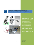
1
Specification for Equipments/Instruments
1. –Laminar Air Flow System Model- Vertical
Suitable for ICU OT
HEPA filtered
SS Body (304 Grade)
Vertical Type size- 4’ 2’ 2’.
2. Solar System
TIEC 61215 Approved Solar Modules
Module Efficiency till 16%-17%
UL/TUV approved junction box
Class electrical rating, IP 65
High Breakdown Voltage resistance
Specifications
Module Rating- 12V/18V/24V, 2W to 300WP
Module Type- Mono Crystalline/ Multi/Poly Crystalline
Cell Efficiency- 12%-18%
Encapsulation- Glass/EVA/Cell/Tedler
Counter Sunk- Screws for frame or screw less joining through box frames.
3. Electrically Powered, Computer Controlled Ventilator
Ventilation Performance and Controlled Parameters
Respiratory Rate
1 to 80 BPM
Tidal Volume
50 to 2,000 ml
Inspiratory Pressure limit
5 to 80cm H20
Inpiratory Time
Adaptive Timetm or 0.2 to 3 seconds
Peak Flow
Adaptive Flow tm or 1 to 120L/min.
Spontaneous up to 180L/min
Oxygen mix (FIO2)
21% to 100%
PEEP
0 to 40cm H20
Trigger Sensitivity
1 to 20 L/min flow Sensitivity +off- 0.5 to -20cm H20
pressure sensitivity +off.
PSV
0 to 60cm H20
Positive Pressure Relief Valve80cm H20
Synchronized Nebulizer
10-240 Minutes
Monitoring and Displayed Parameters
Airway Pressure (analog bar graph & numerical)
Total Breath rate
I.E Ratio
Exhaled Tidal Volume
Exhaled minute volume
Peak Flow
Insipiratory Time
Electrical power Source external/internal)
Battery level
Pressure , Flow and volume waveforms software package:
Real time pressure and flow waveforms waveform history browse.
Trending of monitored data (72 hours)
Respiratory Mechanics (C,R, MAP, PR/Vt) pressure, Flow and volume Loops
SPO2 (Optional)
User Adjustable Alarms
Respiratory rate (high/low) Minute Volume (high/low) Pressure (High/Low)
Low vt (15%-85%)
SPO2 (High/Low)
HR (High/ Low)
Apnea ( 0 to 120 Seconds)
FIO2 (High/Low)
Leak (0 to 100%)]
Additional Alarms and Indicators
Alarms
Inverse I.E. Ratio
Low O2 Pressure
AC Disconnect
Low Battery
Over Temperature
Service Notice
Patient Disconnect
Check Sensor
High Peep
Indicator
Alarm Silence Icon & Timer
Breathe Type Icon
Internal Battery Use
Date & time
Hour Meter
Battery Charge level
Need Calibration
LED: on, Charge, Alarm
Size and Weight
Dimensions:
Height 13’’/33cm
Width 9.5”/24cm
Depth 10.3”/26cm
Screen 8.4” diagonal
Weight 17.6 IB/8.0 kg (without battery)
Overall weight with standard battery 24.2 IB/11.0kg
Overall weight with extended internal battery 27.8 ib/12.6 kg
Power Supply
External AC
External DC
Internal Battery
Operating time
100 to 240v, 50 to 60 HZ, Max 2.0 A
12 to 15 V, max 8.5 A
Sealed lead-Acid 12 V (7.8 AH)
(Rechargeable)
Depending on ventilator settings and impedance- standard internal
up to two hours, optional extended internal up to four hours and
optional external up to nine hours.
Oxygen (Enrichment) Supply
High Pressure Supply 40to 60 psi (2.8 to 4.2 bar)
Low Pressure
Max 15L/min or 0.5 psi
External Interface
Remote Monitor (VGA)
RS-232 Serial port, 9 Pin
DIN Keyboard Connector
RJ11 Remote Alarm Connector
Environment Specifications
Operating Temperature
Storage Temperature
Relative Humidity
Water/Dust Resistance
0 to 50.C/32 to 120.F
15 to 70.C/-4 to 140.F
15 to 95% at 30.C/85.F
IP54 (Splash Proof)
Atmospheric Pressure
430 to 825 mm Hg (15.000 feet)
shock
total external sound level
IEC 68-2-6 and IEC 69-2-34
MIL-STD-810E
IEC 68-2-27 (100g)
40-45 dBa at one meter
4. Crash Cart
Overall approx dimension: 960 mm Lx 500mm W x 1545 mm H Stainless steel tubular
frame and stainless steel shelves. Six colored removable bins and two polystyrene
lockable storage units with three drawers have containers of different sizes. Four 125
dia. Castor wheels with high grade synthetic body, two with brake and two without
brake. Complete with corner buffers, powder coated oxygen cylinder holder, cardiac
massage board, stainless steel I.V. rod. Supplied in KDC.
5. Patient trolley
1710- Traumacare- Emergency and recovery trolley Hi-Io, Raising Backrest, Two way
longitudinal Tilt.
- Over all approx dimension: 1905 mm L x 710 W. Stretcher dimension approx: 1830
mm L x 555 mm W. Two section top. Height adjusted by foot operated imported
hydraulic pump fro, 660 mm to 910 mm. X-ray permeable removable stretcher top in
two sections made of pre-laminated board supported on tubular frame, backrest raised
on ratchet. Gas spring assisted trendelenburg/ reverse trendelenburg positions. Four
125 mm dia. Castor wheels with high grade synthetic body, two with brake and two
without brake. Complete with corner buffers, synthetic rubber covered handles, sliding
X-Ray cassette holder, storage tray, oxygen cylinder holder, stainless steel telescopic
I.V. pole with four locations and swing-away type stainless steel side rails. Pre-treated
and powder coated finish. Supplied in SKD condition.
6. Instrument Trolley (with Stainless Steel Bowl & Tray)
Overall approx dimension: 680 mm L x 450 mm W x 900 mm H. Stainless steel tubular
frame mounted on four 125 mm dia. Castor wheels with synthetic body, two with brake
& two without brake. Two stainless steel shelves with protective railings on three sides.
With stainless steel bowl and tray. Supplied in SKD condition.
7. Mayo’s Table (Stainless Steel)
Adjustable height of tray from approx. 760 mm to 1270 mm. Approx Tray dimension:
560 mm L x 400mm W. Stainless steel tubular frame mounted on four swivel, synthetic
body castors 50 mm wheel dia. Without brake. Supplied in SKD Condition.
8. Revolving Stool
Tubular tripod based with stainless steel revolving top. Height adjustable from approx.
480 mm to 670 mm by accurately machined screw mechanism. Legs fitted with rubber
feet. Pre-treated and powder coated finish.
9. Revolving Stool Fully Stainless Steel. (with M.S. Screw and Nut)
Tubular tripod based with stainless steel revolving top. Height adjustable from approx.
480 mm to 670 mm by accurate machined screw mechanism. Legs fitted with rubber
feet.
10. ANAESTHESIA VENTILATOR (for ICU)
It should be simple to operate electronic lung ventilator, should be able for providing anesthetic
ventilation in operation theatres, using Bains Circuit and Circle Absorber System.
Features
Micro-controller based
No external driving gas pressure
CMV,ASSIST+CMV,SIMV modes
Variable I/E ratio
Apnea backup ventilation
Inspiratory Hold for better distribution of gas
Can be used in OTs with Circle absorber/Bains Circuit
Port for Oxygen enrichment
Adjustable airway pressure safety valve
Comprehensive alarms
Bright display of parameters
Low power consumption
Low maintenance
Classification
Modes
Tidal Volume
Frequency
Inspiratrory
I/E ratio
Inspiratory hold
Apnea Backup
Alarms
Safety Valve
Driving Source
Power Consumption
Weight
Dimensions
Flow Generator Type
CMV, CMV+Assist & SIMV
50 to 1200ml
6 to 40bpm (1 to 40bpm in SIMV)
0.4 to 3 seconds
1:1 to 1:5
0 to 2 Seconds
Every 4 secs in case of Apnea.
Patient Disconnection, High/Low Pressure
Adjustable: 10 to 60cm H2O
220V AC
60W
12kgs
4710x230x280mm
11. ANAESHESIA WORKSTATION
ANAECTHESIA WORKSTATION IS A High end Anesthesia workstation that has an in built
Electrically Operated Micro-Controller Based Ventilator & One Temperature Compensated
Vaporizer.
ANAESTHESIA VENTILATOR (Electrical Driven)
Micro-Controller based
No need of driving gas
Compatible with Circle Absorber Bain’s Circuit
Adjustable safety valve{10 to 60 cm H2O}
Automatic spill device
Bright display of parameters
Inspiratory hold for better distribution of gas
Variable I:E ratio
Display pressure in bar graph
Comprehensive alarms {Patient disconnection & High pressure}
Modes
Tidal Volume
: CMV
Frequency
: 50 to 1200ml
Inspiratory time]I/E ratio
: 6 to 40bpm
I/E ratio
: 1:1 to 1:5
Inspiratory hold
: 0 to 2 secs
Structure
Made of Aluminum Extruded tubes with Polyurethane coated finish. Equipped with non-ferrous
accessory and SS fasteners.
Drawers fitted with sliding channels for smooth movement.
Sliding writing tray at middle table for use.
Four nos. big diameter Castro Wheel with Antistatic tire material. Front Castors are equipped with
individual brakes or double locking type (both rotational lock & movement lock).
Mounted with one No. Dip stand with four hooks.
Handle suitable fitted in both the legs for maneuverability.
Equipped with Electrical Distribution box at the back with 4 nos. 5/15Amps 5 pin socket, one no 2
pin socket & one no. On/Off switch with Extension cord.
Space for mounting up to two nos. vaporizers.
Gas Inlet
Cylinder inlet: Four nos. Forged brass pin indexed Yoke, 2 nos. each fro O 2 & N2O. Yokes are
identified for their gas application by clear marketing on the top & are fitted with filter at
inlet and stainless steel fittings.
Pipe line inlet: Non-interchangeable pipeline connection for O2, N2O & Air.
Pressure Regulators: 2 stage regulation
Each gas service is fitted with high performance Metal diaphragm regulators for first stage
reduction.
Second stage reduction is carried out by Low pressure regulators for each gas service.
Pressure Indicators (Pressure Gauges): High & Low Pressure
The Pressure gauge panel is mounted with big 63mm diameter pressure gauges for individual
cylinder pressure indication of O2 & N2O. The gauges are identified by the gas service marked on
them as well as by Color coding.
The gauge pane is also equipped with Line pressure gauges for monitoring of line pressure for O2,
N2O & Air. Vacuum system also equipped with vacuum gauges fro monitoring vacuum level.
Sl.no
Application
Gas Service
Qty
Range
1
2
3
4
5
6
Cylinder pressure
-DoPipe Line
-Do-DoVacuum System
Oxygen
N2O
Oxygen
N2O
Air
Vacuum
2
2
1
1
1
1
0-250 kpa x 100
0-100kpa x 100
0-10 kg/cm2
0-10 kg/cm2
0-10 kg/cm2
0-760 mm/Hg
Flowmeter with Oxygen Ratio Controller:
a)
b)
c)
ANAECTHESIA WORKSTATION is equipped with a Five Tube Flowmeter for flow
control of O2, N2O & Air. It is fitted with high low range tubes for each O2 & N2O for
precise control of gas flow in the low flow range.
Gas
Oxygen
Flowmeter
Double
N2O
Double
Air
Single
Range
0.1-1 ltr/min
1-12 ltr/min
ltr/min
1-12 ltr/min
100-15000
cc/min
Unique Flowmeter design ensures easy service and maintenance. Each as control valve is
fitted with colour and shape specific knobs as per standard practice.
ANAECTHESIA WORKSTATION Flowmeter is fitted with Oxygen Ratio controller
block to ensure a minimum 25% level of Oxygen in the O2 & N2O mixture
Pneumatics:
High pressure tubing carry cylinder pressure and are made of nickel –chromium plated copper. It
has gas connection and non-interchangeable.
Low pressure tubing are colour coded PU tube of different diameters. Differents pneumatic valves
and connectors used in the system for required application.
Oxygen low pressure alarm:
This safety device generates an audio & visual alarm when oxygen pressure in the rotameter falls
below 1 lts.
Air/ N2O Interlock:
This interlock system eliminates the possibility of selecting Air with N2O even by mistake by the
user. The selection of Air- O2, or, N2O- O2 system has to be selected by this selection switch.
Vaporizer manifold:
ANAECTHESIA WORKSTATION provides mounting facility upto 2 nos. vaporizers. It can
accommodate conventional vaporizers as well as temperature compensated vaporizers with
different types of mountings. It is always recommended to use temperature compensated
vaporizers.
Non Return Valve Block:
This valve is mounted after vaporizer block in the pneumatic circuit and has dual function. First it
restricts reverse flow for gases patient circuit towards vaporizers and seconds, it acts as a safely
blow off valve to limit the pressure of the mixed gas in circuit.
Oxygen Flush:
This flush unit is designed to supply emergency oxygen to the patient at the rate of 35-75 1 pm.
The push switch of the unit is mono stable and to be pressed for use.
Vacuum System:
ANAECTHESIA WORKSTATION has in built vacuum generating device equipped with
vacuum ON/OFF switch, control valve fro vacuum pressure, vacuum pressure gauge and vacuum
outlet. The vacuum system is operated by Air supply.
Gas Outlet:
The machine is equipped with 2 nos O2, 1 Air, 1 no. vacuum outlet.
Basal Flow with O2 cut off swithch:
Ensure apporx. 150ml/min. of O2 flow to the patient circuit when the machine is connected to the
Gas supply. The O2 cut off switch stops the flow when the machine is not in use.
Feature of Flow Circle system:
Ideally suitable for Low Flow anesthesia system.
O-ring fitted taper joints ensure 100% leak proof system and easy to changeover.
Jars can be connected and disconnected very easily.
Supplied with two nos. Jars. APL Valve & Patient circuit.
Visual Unidirectional flow indicator at Inspiratory & Expiratory valve.
Supplied with Bag-vent switch for easy changeover between manual & Automatic mode.
Can be used with all types of Anesthesia Machine.
12. Implant
a) DHS Plates
Material- Stainless steel (instruments)
The implant should be indicated for the treatment of the following fractures:
1. Pertrochanteric and intertrochanteric fractures of type 31-A in the AO/SIF classification.
2. For highly unstable types of fracture, additional implants such as the DHS trochanter
stabilizing plate or DHS locking device may be required.
3. Femoral neck fractures 31-B2/B3, in conjuction with the use of an anti-rotation screw.
b) DHS Plates 130.-150.
Material- Stainless Steel
Fixation with cortex screws_ 4.5mm
Lengths: 46-270 mm (2-16 holes)
Thickness: 5.8mm
Width: 19mm
Hole spacing: 16mm
Barrel lengths: 25 and 38mm
c) DHS Lag Screw
DHS/DCS Screws
Material- Stainless Steel
Lengths: 65-110mm
Thread diameter: 12.5mm
Thread length: 22mm
Shaft Diameter: 8.0mm
It should have a gliding mechanism to prevent the implant from perforating the acetabulum if
the fracture zone slips under stress.
d) DHS Compression Screw
The compression screw is used together with the DHS and DCS plates.
It is used in pertrochanteric fractures to compress the femoral fragments on the proximal and
distal sides of the fracture.
The DHS/DCS compression screw must be used if a DCS plate is applied to the distal femur.
Steel
Inner hexagon for Hexagonal Screwdriver
Length: 36 mm
e) DCS Plate 95
Steel
Fixation with cortex screws_4.5mm
Lengths: 114-370mm (6-22 holes)
Thickness: 5.4mm
Width: 16mm
Barrel length: 25mm
f) Indication for DCS plates
Proximal femur: very proximally located, purely subtochanteric fractures or types 32-A
1.1, A 2.1, A 3.1, 32-B, 1.1, B 2.1, B 3.1.
Fracture of type 33-A (extra-articular, supracondylar fractures of the distal femur)
Fractures of type 33 C-1/C2/C3 (fully articular fracture of the distal femur).
g) LCP DHS
The implant should be indicated for the treatment of fractures such as pertrochanteric
fractures. Intertrochanteric fractures, lateral fractures of the neck & Trochanteric
fractures with subtrochanteric extension.
The cortical screws should be made of titanium and be self-tapping.
The instrument must allow for use of locking screws giving angular stability.
The instruments should have tapered ends to allow for sub muscular insertion of the
plate.
The instrument should be compatible with Trochanter Stabilizing Plates.
The instrument should be available with ling barrel (38mm) and short barrel length of
(25mm)
The DHS barrel plate should be available in the following CCD angles: 130., 135.,140.,
145 and 150.
The DHS barrel plate should be available in 2-6 holes.
4.5mm cortical screws/ 5mm locking screws should be of length from 28mm to 54mm.
Synthes LCP product is protected by numerous patents throughout the world including
Indian Patent no 195986.
h) DHS Blade
The shape of the blade should help in improving rotational stability.
The blade should have an increased support surface resulting in a lower risk of cut-out
in osteoporosis bone.
The DHS Blade should be compatible with the conventional DHS & LCP DHS plate.
The specially designed tip to the blade should allow for compaction of the bone when
the blade is inserted.
Available in sizes of 65mm-120mm increments for 5mm in Stainless Steel & titanium
both.
i) S.U.N- Tibial interlocking Nail
Indicated for Tibial shaft (42-A, B, C) fractures
Anatomical femoral and tibial nail designs provide optimal fit in the medullary canal
Anatomical femoral and tibial nail designs reduce stress concentration during nail
insertion.
Guided proximal and distal locking possible.
Cannulated nails allowing nail insertion cover a guide wire.
Tibial nail’s unique proximal end uses one conical bolt and insertion handle for all nail
diameters.
Tibial nail’s beveled proximal end prevents irritation of the soft tissue after
implantation .
Tibial nail’s special tapered tip prevents penetration of the posterior cortex in the
proximal fragment while minimizing further communution.
The AO/ASIF curvature of 11. in the upper third of the S.U.N. tibia (tibial interlocking
nail) allows for easy insertion and good anatomical fit.
Availabel in a wide range of diameters and lengths:
Universal tibial nail: 9mm dia and 270-360mm lengths (15mm increments), 10-12mm dia and
285-360mm lengths.
j) S.U.N- Femur interlocking Nail
Indicated for Femoral (AO 32A,B,C) fractures.
Anatomical femoral nail designs provide optimal fit in the medullary canal
Anatomical femoral nial designs reduce stress concentration during nail insertion
Guided proximal and distal locking possible
Cannulated nails allowing nail insertion over a guide wire
The 1.5m radius of the S.U.N. femur (Femur interlocking nail) corresponds closely
with the average anatomical curvature of the femur.
Available in a wide range of diameters and lengths:
Universal Femoral Nail: 9-123mm dia, and 340-460mm lengths (20mm increments)
k) 7.3mm Cannulated Screws
1. The screws should enable accurate & safe screw positioning: a decisive advantage when
treating fractures near joints
2. The screws should be cannualate d for enabling passage of Kirschner wires.
3. The 7.3mm self-frilling, self- tapping cannulated screws should have deep cancellous
threads with reverse cutting flutes. They should be available in 16mm & 32mm two thread
lengths with rigid 2.8mm guide wire, made of high strength L-605 alloy.
4. 7.3mm cannulated screws should be indicated for fixation of fractures involving large
fragments, such as:
Femoral neck fracture sin adults
Femoral neck fractures in adolescents
Slipped capital femoral epiphyses
Intracondylar fractures of the femur
Tibial plateau fractures
Dislocation of the acromioclavicular joint
Ankle authrodesis
Sacro-Iloac joint disruptions.
l) Distal Femoral Nails (DFN)
All implants must be made of Titanium.
The nail should be indicated for the stabilization of fractures of the distal femur.
It nail should be used for diaphyseal fractures in which a retrograde approach is indicated
(e.g. insilateral tibia and /or patella fractures, proximal or distal endoprosthesis, adipositas
permagna, supracondylar femoral fractures).
One nail design for angular stable locking of spiral blade in osteoporotic bone and standard
locking.
The nail dia. Must be 10.0mm with a length of L 340 to 380 mm of 5 pcs each- 15 pcs in
total.
The nail dia. Must be 12.0mm with a length of L 360mm of 5 Pcs in total.
The quantity of locking screws 6.0 ,, doa must be 20 pcs. Each size of 65 & 75mm- 40 in
total.
The implants must be compatible with existing synthes instruments.
m) DHS-TSP (Trochanter Stablising Plate)
The DHS-TSP Plates should offer anchoring options for the fixation of fragments of the
greater trochanter.
The plate should have an aperture ofr an antiroation screw & an oval aperture for the
DHS/DCS screw.
The scooped section of the plate should be able to adapt to the anatomical contours of the
greater trochmeter. The area of bone loss (Porosis) as observed beneath a limited contact
plate should be less than below a full contact plate
The uniform stiffness of the LC-DCP should enable continuous curvature, allows a good fit
of the screw head in the plate hole, and preserves the fundamental mechanical qualities of
the plate. When loaded. The uniform stiffness of the LC-DCP should allow an even
distribution o stresses over a long distance along the plate, protecting the plate holes from
localized high stresses.
The LC-DCP hole should allow for bidrectional compression.
It should allow for 80 degrees of longitudinal screw angulation nad 14 degrees of
transverse screw angulation.
The LC-DCP plates should be made of pure Titanium, which display excellent
biocompatibility. Pure titanium and its wear products behave passively and provoke neither
toxic nor allergic reactions.
n) T-Buttress Plate 4.5mm
4.5 mm LCP® T- Buttress Plates, 2 holes head
Available in 4, 5 shaft holes (83mm, 99mm respectively)
Precontoured
Plate contains Combi holes in the shaft, locking holes in the head
Synthes LCP product is product is protected by numerous patents throughout the world
including Indian Patent no 195986.
o) L-Buttress Plate 4.5mm
4.5 mm LCP® L- Buttress Plates, 2 holes head, Right leg
Available in 3,4,5,6 shaft holes (69mm, 85mm, 101mm, 117mm respectively)
Precontoured
Plate contains Combi holes in the shaft, locking holes in the head
Synthes LCP product is product is protected by numerous patents throughout the world
including Indian Patent no 195986.
4.5 mm LCP® L- Buttress Plates, 2 holes head, left leg
Available in 3,4,5,6 shaft holes (69mm, 85mm, 101mm, 117mm respectively)
Precontoured
Plate contains Combi holes in the shaft, locking holes in the head
Synthes LCP product is product is protected by numerous patents throughout the world
including Indian Patent no 195986.
p) Tibial Head -Buttress Plate 4.5mm
4.5 mm LCP® T- Buttress Plates, 2 holes head
Available in 4, 5 shaft holes (83mm, 99mm respectively)
Precontoured
Plate contains Combi holes in the shaft, locking holes in the head
Synthes LCP product is product is protected by numerous patents throughout the world
including Indian Patent no 195986.
4.5 mm LCP® L- Buttress Plates, 2 holes head, Right leg
Available in 3,4,5,6 shaft holes (69mm, 85mm, 101mm, 117mm respectively)
Precontoured
Plate contains Combi holes in the shaft, locking holes in the head
Synthes LCP product is product is protected by numerous patents throughout the world
including Indian Patent no 195986.
4.5 mm LCP® L- Buttress Plates, 2 holes head, left leg
Available in 3,4,5,6 shaft holes (69mm, 85mm, 101mm, 117mm respectively)
Precontoured
Plate contains Combi holes in the shaft, locking holes in the head
Synthes LCP product is product is protected by numerous patents throughout the world
including Indian Patent no 195986.
q) T-Plate 4.mm
4.5 mm LCP® T- Plates, 4 holes head, Right angle.
Available in,4,6,8 shaft holes
Plate contains Combi holes in the shaft, locking holes in the head
Synthes LCP product is product is protected by numerous patents throughout the world
including Indian Patent no 195986.
r) LC-DCP 3.5mm
The limited contact plates should achieve uniform stiffness all along the plate length
despite limited bone contact. There should be reduction of the surface contact between the
plate and the bone resulting in a reduced disturbance of the blood supply.
LC-DCP 3.5 system should be available from 25mm- 155mm.
The plates should consolidate with reduced porosis. The area of bone loss (porosis) as
observed beneath a limited contact plate should be less than below a full contact plate.
The uniform stiffness of the LC-DCP should enable continuous curvature, allows a good
fit of the screws head in the plate hole, and preserves the fundamental mechanical qualities
of the plate. When loaded. The uniform stiffness of the LC-DCP should allow an even
distribution of stresses over a long distance along the plate, protecting the plate holes from
localized high stresses.
The LC-DCP hole should allow for bidirectional compression.
It should allow for 80 degree of longitudinal screw angulation and 14 degree of transverse
screw angulation.
The LC-DCP plates should be made of Stainless Steel.
s) Semi tubular Plate 4.5mm
4.5 mm Semi tubular Plates, St. Steel
Available with 2-12 holes (39mm-199mm lengths)
Hole spacing 16m, width 11mm and thickness is 1.5mm.
Available in Stainless Steel
Synthes LCP product is product is protected by numerous patents throughout the world
including Indian Patent no 195986.
t) 1/3rd tubular Plate 4.5mm
Available with 3-10 holes (33mm-117mm lengths) and 12 holes (141mm)
Plate contains only locking holes that accept 3.5mm locking screws, 3.5 mm cortex
screws, and 2.7mm cortex screws.
Synthes LCP product is product is protected by numerous patents throughout the world
including Indian Patent no 195986.
u) (CFN) – Cannulated Femoral Nails
The nails should be made from Titanium and is cannulated.
Solid nail design- 9mm, 10mm & 11mm with length from 340mm to 420mm
One nail for both right and left femour
Threaded proximal end-provides direct connection
1.5m radius of curvature to provide anatomic fit in femur
One proximal Dynamic hole that should permit 8mm of controlled axial movement for
dynamisation. One transverse proximal hole medial-lateral locking to place locking bolts in
strong cortical bone should provide rotational control in proximal fractures.
There should be two distal locking holes for placement of transverse locking bolts, which
provide rotational control, maintain femoral length and alignment and stability in low distal
fracture. Distal M-L locking hole about 20mm from nail tip should permit locking of most
distal fractures.
Countersunk locking holes should minimize stress concentrations in nail, improve load
distribution on locking bolts, and ease distal locking procedure.
The tip should be tapered which reduces possibility of penetration of posterior cortex in
proximal fragment and minimized further comminution of fracture site.
The length should be available in 20mm increments starting from 34cm to 42cm.
Each nail should be provided with an end cap which should be capable to extend the nail
from 0 to 20mm.
Bevelled tip for easy insetion
Optional hole in nail for very distal fracture
Cannulation for reamed or undreamed technique
Titanium alloy material for improved mechanical and fatigue properties.
Choice for static and synamic locking in distal end of the nail
MRI compatibility
Self tapping locking bolts
Nail sizes left and right dia 9, 10 and 11mm of lengths 340 to 440mm (2mm increments)
605mm hip screws of length 75mm to 110mm (5mm increments)
4.9mm locking bolts of length 26 to 68mm (2mm increments)
End caps of 0 to 10mm
TUV certified.
v) Proximal Femoral Nail (PFN)
It should have
Anatomical design with 6ML angle
Proximal dia between 16 to 18mm
CCD angle of 130
Entry point form tip of the greater trochanter
Two locking option for neck
Neck screw with safety stop to prevent slippage thorough the nail into the femoral neck
A derotainal hip pin option
End cap to protect form tissue in growth in the nail
Choice for static and dynamic locking in distal end
Titanium alloy material for improved mechanical and fatigue properties.
MRI compatibility
Nail sizes left and right dia 10 and 11mm of lengths 200 to 400
Neck screw of 11mm of length 80 to 110mm (5mm increments)
Hip pin of 6.5mm of length 75 to 100mm (5mm increments)
End caps with no extension
TUV certified
x) Proximal Femoral Nail Antirotation (Asian Version) (PFNa-II)
The nail is suitable for the Asian anatomy, it should have
Anatomical design with 6ML angle
Proximal dia between 16 .5mm
CCD angle of 130
Entry point form tip of the greater trochanter
One locking option for neck with the PFNa Blade which is cannulated, with cutting edges
to enable easy insertion and is ideal for oseoporotic bone.
End cap to protect form tissue in growth in the nail
Choice for static and dynamic locking in distal end
Titanium alloy material for improved mechanical and fatigue properties.
Radiolucent jig for proximal locking of blade and for dynamic distal locking.
MRI compatibility
Nail sizes left and right dia 10 and 11mm of lengths 200 to 420
TUV certified
y) Distal Femur locking compression Plate (DF-LCP)
All implements should be made of titanium only.
Plate Length should be- 156mm, 236mm & 316mm with no of holes as 5, 9 & 13.
Guiding block which get fixed on to the distal head of the plate and enable right insertion
of locking head screws.
Locking head screws should be self-drilling, self-tapping
The plate holes should have thread to lock the screws to avoid pull out in case of lossening.
The locking head screw should ensure angular stability for an optimal anchorage in the
bone and improved biomechanics.
Optimized screw angulation and screw position of a safe fixation even in case or very distal
fractured.
Anatomical pre-shaped plates and self-drilling, selt-tapping screws to reduce surgery time.
Radiolucent insertion guide to slice the plate under the muscle and to insert the screws
percutaneously.
Synthes LCP product is protected by numerous patents throughout the worlds inclosing
Indian Patent no 195986.
z) Metaphyseal Plate 3.5mm 4.5mm
It should have
Two different profile in the plates for optimal application in metaphy seal area
Combination hole for standard and locking screws
Two distal hole with the direction towards centre of the plate
Titanium material for improved mechanical and fatigue properties.
Tapered, rounded plate tip for easier application
Self tapping screws
Sizes 3.5mm 6 to 18 holes, 3.5/4.5mm 8 to 20 holes
Standards screws 3.5mm length 14 to 60mm (2mm increments)
Standards screws 4.5mm length 14 to 60mm (2mm increments)
Locking head screws 5.0 mm length 14 to 60mm (2mm increments)
Locking head screws 3.5mm length 14 to 60mm (2mm increments)
Cancellous screw 4.0mm with half and full thread of lengths 20 to 50mm (2.5mm
increments)
Cancellous screw 4.0mm with half and full thread of lengths 30 to 95 mm (5mm
increments)
MRI compatibility
TUV certified
Synthes LCP product is protected by numerous patents throughout the worlds inclosing
Indian Patent no 195986.
a.a) Tibial Nail for metaphyseal and Diaphyseal fractures- ETN (Expert Tibial Nail)
It should have
Multiple locking option in both distal and proximal part of the nail
Proximal part of the nail should have multi directional locking option and should accept
both cancelleous bone locking screws and standard locking screws
The end cap should have the possibility to block one locking screw with the end cap for
absolute angular stability
The locking screws hould have recess for effortless pick-up and secure locking. Further
they should have double thread for more contact points leading to enhanced stability.
The nail material should be titanium alloy for improved mechanical and fatigue properties
All nail should be cannualated for reamed or undreamed technique.
Sizes dia 8, 9, 10mm-lenghs 285 to 405 (15mm increments)
Locking head screws 4.0 mm length 18 to 60mm (2mm increments)
Locking head screws 5.0mm length 26 to 60mm (2mm increments)
Cancellous screw 5.0mm with half and full thread of lengths 30 to 80 mm (5mm
increments)
End caps of 0 to 15mm
TUV certified
MRI compatibility
a.b) Solid tibial (Unreamed Tibial Nail-UTN)
If should have
Flattened proximal end to prevent irritations of the patellar tedons
Dynamic, static and oblique locking hole in proximal part
Titanium alloy material for improve mechanical and fatigue properties
Self tapping locking bolts
Sizes dia 8, 9 and 10mm of lengths- 285 to380mm (15mm increments)
Locking bolts 3.9mm and 4.9mm of lengths (2mm increments)
Threaded proximal end which prevents irritation of patellar tedon & other soft tissue.
9 proximal bend for 3 point contact with bone.
Oblique locking hole about 30mm form proximal nail end.
The nail should be solid.
Anteromedial to posteromedial or antero lateral to posteromedial procurement of most
proximal locking bolts hold in metaphyseal bone for fixation of high tibial fractures.
Dynamics hole which should permit 10mm of controlled coaxial movement for
dynamisation transverse proximal holes to place locking bolt in strong cortical bone,
provides rotational control in proximal fractures.
Distal A-P locking hole should be 25mm to 28mm from nail tip and should permit
locking of more distal fractures.
Two distal locking holes for placement of transverse locking bolts to provide rotational
control maintain tibial length and alignment and stability in low distal fracture.
The tip should be tapered to reduce possibility of penetration of posterior cortex in
proximal fragment and minimzed further comminution of fracture site.
Each nail should be provided with an end cap of 6mm to prevent bone growth
Locking screws should also be made of Titanum (Medical Grade).
a.c) Cannulated tibial nail-CTN
It should have
Flattened proximal end to prevent irritations of the patellar tedons
Dynamic, static and oblique locking hole in proximal part
Titanium alloy material for improve mechanical and fatigue properties
Self tapping locking bolts
Sizes dia 10mm-11mm of lengths- 285 to380mm (15mm increments)
Locking bolts 3.9mm and 4.9mm of lengths (2mm increments)
Threaded proximal end which prevents irritation of patellar tedon & other soft tissue.
9 proximal bend for 3 point contact with bone.
Oblique locking hole about 30mm form proximal nail end.
The nail should be solid.
Anteromedial to posteromedial or antero lateral to posteromedial procurement of most
proximal locking bolts hold in metaphyseal bone for fixation of high tibial fractures.
Dynamics hole which should permit 10mm of controlled coaxial movement for
dynamisation transverse proximal holes to place locking bolt in strong cortical bone,
provides rotational control in proximal fractures.
Distal A-P locking hole should be 25mm to 28mm from nail tip and should permit
locking of more distal fractures.
Two distal locking holes for placement of transverse locking bolts to provide rotational
control maintain tibial length and alignment and stability in low distal fracture.
The tip should be tapered to reduce possibility of penetration of posterior cortex in
proximal fragment and minimzed further comminution of fracture site.
Each nail should be provided with an end cap of 6mm to prevent bone growth
Locking screws should also be made of Titanum (Medical Grade).
a.d) LCP Calcaneal Plate 3.5mm
Available in four sizes: 64, 69, 76 and 81mm for left & right.
In Titanium only.
The plate is low profile 3.5mm and is flexible and adaptable . It can be easily cut
and contoured. The diagonal arm stabilizes the sustentaculum and support talocalcaneal joint/
Angular stable fixation can be provided. By using 2.7mm and 3.5mm standard
cortex screw & Cacellous 4.0mm intrafragmentary cipression can be achieved.
Synthes LEP product is protected by numerous patents throughout the world
including Indian Patent no. 195986.
a.e) LCP Broad Curved Plate 4.5/5.0mm
Indicated for periprosthetic fractures of femur when nail is not indicated.
The plate can be used together with the periprothetic locking head screw or in combination
with cerclage fix and cerclage wiring.
Available in Titanium only.
The plate is anatomically pre-shaped with the radius of 15m and fits ideally on to the
femur.
The small hole in the bullet ends of the plate allows primary fixation with K-wires.
Available from 12 to 22 holes from length of 229mm to 408mm increments of 18mm.
Additional implants include a spacer and cerclage fix.
5.0mm locking head screws are used with plates
Synthes LEP product is protected by numerous patents throughout the world including
Indian Patent no. 195986.
a.f) LCP Anterolateral Distal Tibia Plate 3.5mm
Anatomically pre-shaped low profile plate
Two different plate designs to fit right or left tibia indicated with R or L on plate
Shaft holes accept locking screws 3.5mm, cortex screws 2.7mm and B 3.5 mm and
cancellous bone screws 4.0mm.
Head holes accept locking screws 3.5mm, cortex screws 2.7mm and B 3.5mm and
cancellous bone screws 4.0mm.
Tapered tip for submuscular insertion
Screw heads are recessed in the plate to minimize screw prominence
Available in titanium.
Size range from 5 to 21 holes increments of 26mm.
Length of 80mm to 288mm increments of 26mm.
Synthes LEP product is protected by numerous patents throughout the world including
Indian Patent no. 195986.
a.g) LCP Proximal Medial Tibia Plate 3.5mm
Anatomically pre-shaped low profile plate
Two different plate designs to fit right or left tibia indicated with R or L on plate
Three convergent threaded screw holes accept locking screws 3.5mm or cortical screws
3.5mm.
Two 2.0mm holes for preliminary fixation with Kirschner wires, or meniscal repair with
sutures.
The two angles locking holes distal to the plate head accept locking screws 3.5mm or
cortical screws 3.5mm to secure the plate position.
Available in titanium.
Size range from 4 to 20 holes increments of 2 holes.
Length of 94mm to 301mm increments of 26mm.
Synthes LEP product is protected by numerous patents throughout the world including
Indian Patent no. 195986
a.h) LCP Distal Medial Tibia Plate 2.7/ 3.5mm
Anatomically pre-shaped low profile plate
Two different plate designs to fit right or left tibia indicated with R or L on plate
Less invasive insertion.
The round threaded holes in the distal section of the plate allow the insertion of locking
screw 3.5mm & 2.7mm.
Articulated tension Device (ATD) hole for compression or distraction.
Rounded edges to minimize soft tissue irritation.
Three distal locking screws diverge across subchondral bone and are parallel to joint.
Available in titanium.
Size range from 4 to 14 holes increments of 2 holes.
Length of 116mm to 246mm increments of 26mm.
Synthes LEP product is protected by numerous patents throughout the world including
Indian Patent no. 195986
a.i) LCP Proximal Tibia Plate 3.5mm
Anatomically pre-shaped low profile plate
Two different plate designs to fit right or left tibia indicated with R or L on plate
Three 2.0 mm holes for preliminary fixation with K-wires, or meniscal repair with sutures.
Four convergent threaded screw holes accept 3.5mm stardrive or hexagonal locking screws.
The three locking holes distal to the plate head accept 3.5mm Stardrive or Hexagonal
locking screws to secure plate positions. The hole angles allow the locking screws to
converge with three of the four locking screws in the plate head to support medial
fragments.
Combi holes, distal to the three angled locking holes, combine a DCU hole with a threaded
locking hole. The combi holes accept 3.5mm Stardrive or Hexagonal locking screws in the
threaded portion of the hole and 3.5mm cortex screws or 3.5mm shaft screws in the DCU
portion of the hole.
Available in titanium.
Size range from 4 to 16 holes increments of 2 holes.
Length of 81mm to 237mm increments of 26mm.
Synthes LEP product is protected by numerous patents throughout the world including
Indian Patent no. 195986
13. Other
a) Large External fixator
Rod of dia 11mm in
- Carbon fibre
- Lengths 100-400mm
Clamp. Clip-on self-holding MR-safe
Aperture for rods 11mm
All instruments must be enclosed in a syncase with lid
b) Medium External fixator
Rod of dia 8mm in
- Carbon fibre
- Lengths 120-320mm
Clamp. Clip-on self-holding MR-safe
Aperture for rods 8mm
Schanz screw 4mm 7 5mm
All instruments must be enclosed in a syncase with lid
c) Cortex screw 3.5mm
3.5mm Cortex Screws, St, Steel
Available in different size from 10mm to 40mm (increments of 2mm)
3.5mm Cortex Screws, St, Steel
Available in different size from 10mm to 40mm (increments of 2mm)
Also available in size range from 45 mm to 90mm (increments of 5mm)
d) 6.5mm Cancellous Screw
6.5/16mm Cancellous Bone Screw (Stainless steel/Titanium both)
Available in Titanium and stainless steel both
Available in size range 30mmto 120mm (increments of 5mm)
Partially threaded (Threaded length is 10mm)
6.5/32mm Cancellous Bone Screw (Stainless steel/Titanium both)
Available in Titanium and stainless steel both
Length is 130mm with thread length of 115mm
Used with Jacobs chuck
e) Drill bit 4.5mm
Diameter is 4.5mm
Length is 195 mm with thread length of 170mm
Used with quick coupling
f) Drill bit 4.5mm
Diameter is 4.5mm
Length is 180 mm with thread length of 165mm
Used with Jacobs chuck
g) Drill bit 2.7/1.35mm dia, L160/130mm, cannulated
Diameter is 2.7/1.35mm
Length is 160/130 mm
Cannulated
Used with quick coupling
h) Drill bit 3.5/1.35mm dia, L160/130mm, cannulated
Diameter is 3.5/1.35mm
Length is 160/130 mm
Cannulated
Used with quick coupling
14. Power Drills:For Trauma Management
The Cannulated Battery hand piece
Cannulation with 4.1mm diameter
Weight of hand piece 1300gm with Battery
Power of 180W
Continuously variable speed without attachment 0-1450 rpm
Separate forward and reverse triggers
Handipiece is compatable with radiolucent drive
Instant change between clockwise and counterclockwise rotation
Fully Autoclavable
All attachments can be fitted on single hand piece
8 different locking options for attachments
Reliable protection of soft tissue with integrated oscillation mode
Lid for Hand piece
Fully autoclavable
For holding and prevention fall of power module form the hand piece
Mode selector switch to select Drilling/Reaming, Saw, Oscillation
Drill mode
Power Module
There should be a display indication the battery capacity status
Should have a button to diagnose errors in the systems
Not to be autoclaved
Universal Battery Charger II
Should have 4 charging bays
Should be capable of charging NiCd, NiMh and Lithium lon
Batteries
Should display the charging status of the batteries
Keeps inserted batteries constantly fully loaded
Sterile Cover
Made of Stainless steel
Fully autoclavable
For sterile transfer of power module to Battery hand piece
Jacob’s Chuck attachment
Cannulationof 4.1 mm diameter
Chuck range from 0.5 to 6.5mm
Maximum speed of 1450 rpm
Drill Chuck Attachment
Cannulationof 4.1 mm diameter
Chuck range from 0.5 to 6.5mm
Maximum speed of 1450 rpm
Quick Coupling for reaming
Cannulation of 4.1 mm diameter
Maximum speed: 330 rpm
Maximum Torque: 13Nm
Sagittal Saw attachment
It can operate on an oscillation frequency of 0 to 11,000 osc/min.
The amplitude of oscillation should be 4.5.
Attachment can be locked in 8 different positions in steps of 450
5 locking options for the saw blades in the attachments
Saw blade for TJR Surgery length 81 to 116mm, Usable L 60to 95mm, width 12.5 to
25mm, thickness 0.89 to 1.47mm
Saw blade for general traumatology length 46 to 90mm
Usable length 25 to 69mm, width 10 to 50mm, thickness o.4 to 1.2mm
Reciprocating Saw attachments
It can operate on an oscillation frequency of 0 to 11,000 osc/min.
The maximum stroke length for reciprocation saw should be 4mm
Attachment can be locked in 8 different positions in steps of 450
Saw blade for Reciprocating saw length 55 to 80mm, cutting thickness 0.85 to 1.1mm,
width 10 to 12mm.
Should accommodates sternum top
Quick coupling for DHS/DCS Tripple Reamer
Cannulation of 4.1 mm diameter
Speed upto 670 rpm
Quick coupling for K-Write
Sontinours adjustment facility for wire diameter from 1 to 4mm
Speed up to 1450 rpm
CAD Specifications
The Cannulated Pneumatic Drill hand piece
Cannulation with 3.2mm diameter
Air Consumption of 250I/min
Operating pressure: 6-7 bars (maximum 10 bars)
Weight of handpiece 0.8kg without any attachment
Power 120w
Variable speed from 0-900 rpm
Noise level of max 72db
Separate forward and reverse triggers
Safety Device to cut off air supply to drill on hand piece
Handipiece is compatable with radiolucent drive
Instant chance between clockwise and counterclockwise rotation
Offers reliable protection of soft tissues with oscillating drill attachment
Fully authoclavable
Fully machine washable
All Attachments can be fitted on single handpiece
The reverse trigger automatically locks when the oscillating saw and the reduction drive
attachments are attached to handpiece.
Jacob’s Chuck attachment
Cannulation of 3.2 mm diameter
Chuck capacity up to 0 to 6.5mm
Maximum speed of 900 rpm
Torque of 4.7 Nm
Quick Coupling attachment
Cannulated
Maximum speed: 900 rpm
Maximum Torque: 4.7 Nm
Reduction Drive for Intramedullary/ Acetabular Reaming (AO/ASIF Coupling)
Reaming speed of 340 rpm
Reaming Torque of 13 NM
Option of Attachment with reverse rotation
Right Angles Drive for medullary Reaming
Reaming speed of 340 rpm
Reaming Torque of 13 NM
Quick coupling for K-Write
Continuous adjustment facility for wire diameter from 0.6 to 3.2mm
Speed up to 900 rpm
Chuck with Mini Quick Coupling
Cannulated
Maximum speed: 900 rpm
Keyless chuck
Cannulated of 3.2mm
Maximum speed: 900 rpm
Chuck capacity up to 0 to 6.5mm
Torque Limiter
Insertion of screws with limited torque up to 4 Nm
Quick coupling for DHS/DCS Tripple Reamer
Cannulation of 3.2 mm diameter
Speed upto 900 rpm
Oscillating Drill attachments
Oscillations of 270.
Continous frequency regulation: 0-1300/ min
Soft tissue protection during drilling
Radiolucent Drive
Precise aiming and drilling under image intensifier control for locking intramedullary nails
Drill bit diameter 2.0 to 4.5mm, length 106 to 148mm, Usable length 80 to 122mm
Reduce exposure to x-rays
15. QR Trauma
Instrument set
PELRIC C-CLAMP
Quick and efficient compression and stabilization of fractures, and thus control of the
hemorrhage in the unstable posterior pelvic ring.
Should allow for gain in time for subsequent diagnostic or therapeutic means;
The patient can be passed though a CT-Gantry.
Should allow for unrestricted access to the abdomen, pelvis or proximal femur.
The pelvic reconstruction plates should be able to three dimensionally contoured allowing
them to be closely adapted to the pelvic surfaces.
The instruments should include pelvic reduction forceps with pointed ball tips.
The pelvic reduction forceps should allow for clipping with spiked discs.
LC-DCP & DCP Basic Instrument Set (Large)]
Material- Stainless steel
Grade-ISO 5832-1
The surgeon should be able to use these instruments in open reduction and for internal fixation by
plating in fracture of large bones, like femur, tibia and humerus.
The instrumentation should allow for drilling, tapping, compression, neutralization, buttressing and
fixation of 4.5mm cortical screws and 6.5mm Cancellous screws.
It should contain drill bits in 3.2 and 4.5mm dia, taps fro 4.5mm cortical screws and 6.5 mm
cancellous screws, screw drivers, depth gauges, drill guides, bending press for 4.5 mm plates
and contain templates for 4.5mm compression plates and low contact compression plates.
The Instruments should have a Universal drill sleeve 5.4/5mm
A self retaining hexagonal screwdriver with torque limiting attachment having a 4Nm
torque.
The instrument should have LCP Bending iron 4.5/5 for bending the implants
The instrument should have conical extraction screws of length 59mm & 196mm & drill
Bit 3.5mm dia for metal for extraction of damaged screws.
The torque limiting screwdriver should have screw-holding sleeve along with all other
essential instruments to use the implants.
All instruments must be enclosed in a aluminum case.
Reduction forceps set
Material- Stainless steel
Grade-ISO 5832-1
This set should contain forceps for reduction, bone holding and distraction for large bones, small
long bones, patella, fibula and malleoli.
The bone holding forceps should be self-centering and should be available in all sizes.
General Instruments set
Material- Stainless steel
Grade-ISO 5832-1
The Instruments should contain the following for general purpose orthopaedic use. Retractors 8, 18
and 24mm wide, bone hooks, periosteal elevators, Hammer, chisel handle with detachable chisel
blades 10, 16 and 25mm wide, gouges for Concellous bone grafts 5, 10 and 15mm wide, curved
and straight and retractors in various sizes.
DHS/DCS Instrument Set.
Material- Stainless steel
Material- Titanium (implants)
Grade-ISO 5832-1
The instrument should have DHS/DCS® Threaded Guide Wire, 2.5mm dia, L 230/5mm
The instrument should have Angles Guide 135., 150.
The instrument should have DHS/DCS® Direct Measuring Device
The instrument should have Wrench for one-step insertion L 230mm
The instrument should have T-Handle with quick coupling, L 80mm
The instrument should have DHS ® Triple Reamer
The instrument should have Impactor for one-step insertion, L 260mm
The instrument should have DHS/DCS® Tap, L 220mm
The instrument should have locking Centering sleeve
The instrument should have coupling screw, cannulated
The instrument should have Triple Reamer
The instrument should have tapered ends to allow for submuscular insertion of the plate.
The instrument should be compatible with trochanter stabilizing plates.
Wire Instruments Set
Material- Stainless steel
Grade-ISO 5832-1
The Instruments should contain the following for proper insertion, handling, cutting, bending,
holding, and tightening of Circlage, Kirschner wires.
Triple guide wire, wire passers, wire tighteners, holding forceps, wire bending pliers, wire cutter,
wire mounts for compression plates, Circlage wires with eye in 1.00 and 1.25mm dia, length
280mm.
Reamed Interlocking Instrument Set for Femur & Tibia
Material- Stainless steel
Grade-ISO 5832-1
The Instruments should contain the instruments for femoral & tibial interlocking with all reamers
from 9.0mm to 14.5mm with an increments of 0.5mm. the flexible shaft should be made of NITOL
material & must rotate clockwise & counter-clockwise. The instruments must be compatible to
existing branded drill/reamer system to facilitate the quick reaming, etc. the reaming, insertion &
locking device should be complete in all respects.
Broken Screw Removal Set
The plates and screw are the basic requirements of different orthopedic surgeries,
especially in the forearm, the DCP (Dynamic Compression Plates) with 3.5mm screws are
used.
Once the fracture is healed there is an absolute necessity to remove the implants, since the
DCP sinks inside the bone causing severe deformity to the healthy bone.
The DCP with 4.5mm & 6.5mm cancellous screws are also for Humeral, Tibila & Femoral
shaft fractures.
During the removal of the implants most of the time, the screws are broken causing serious
technical problems to the surgeons.
It the instruments are in possession, it is quite easy for the removal of the broken implants.
The set should have screwdrivers & screwdriver shafts, forceps for screw removal, conical
extraction screws with T handle, hollow reamers & extraction bolts with T handle.
Locked Compression Plating System- LCP (Small)
The instruments should have a universal drill sleeve 3.5mm
The instrumentation should have a drill bit of dia 2.8mm & a threaded LCP drill guide for
the drill bit 2.8mm
The instrument should have screwdriver shaft 2.5mm, length 80mm.
The instrument should have LCP bending iron for bending the implants.
A self retaining hexagonal screw driver with torque limiting attachment having a 1.5Nm
torque.
The torque limiting screwdriver should have screw-holding sleeve alongwith all other
essential instruments to use the implants.
The instrument should have conical extraction screws of length 61mm & 136mm & drill bit
2.5mm dia for metal extraction of damaged screws.
All instruments must be enclosed in a syncase with lid.
Locked Compression Plating System- LCP (Small)
The instruments should have a universal drill sleeve 4.5/5mm
The instrumentation should have a drill bit of dia 4.3mm & a threaded LCP drill guide for
the drill bit 4.3mm.
The instrument should have a self retaining screw driver shaft fro 5mm locking head
screws.
The instrument should have LCP bending iron4.5/5 for bending the implants.
A self retaining hexagonal screw driver with torque limiting attachment having a 4Nm
torque.
The torque limiting screwdriver should have screw-holding sleeve alongwith all other
essential instruments to use the implants.
The instrument should have conical extraction screws of length 59mm & 196mm & drill bit
3.5mm dia for metal extraction of damaged screws.
All instruments must be enclosed in a syncase with lid.
Modad (Modular Aiming Device)
The instruments should have image intensifier free distal locking of Tibia, femur &
Humerus.
The instruments should have ML & AP Targeted locking.
The instruments should be compatible with UTN/CTN, UFN/CFN, UHN & SUN Nails.
The instruments should correct nail deformation in the saggital & frontal planes.
The instruments should have L-Spacer for connection between hole &Aiming device.
The instruments should have T Spacer for connection between the nail &Aiming device.
The instruments should have L Curette for taking out bon debris.
The instruments should have twin calibration Pin for checking the calibration.
The assembly should have sterilizing case with an inbuilt stand to hold the proximal jigs of
all nails for calibration.
The assembly should have a pre calibrated scale for fixing the L-Spacers.
Power Reaming System (Sybream)
The power reaming system should:
Have flexible reamer shaft with provision of quick coupling connection.
It should be fitted with T-Handle to hold the reaming shaft.
It should be fitted with straight reduction head & with possibility of quick coupling
attachments to the flexible shaft.
If should have cannulated reamers 8.5mm to 13mm at 0.5mm increments, 8.5mm being end
cutting while all other should be side cutting, with quick coupling.
It should have stainless steel, flexible, ball tip reaming cum guide rod, which should not
pass through the reaming or reduction heads.
It should be supplied with cleaning brush for flexible shaft.
It should be supplied with ratchet lock, grooved forceps for holding of reaming rod.
It should have the provision of stainless steel box to keep, (perforated fro autoclaving) to
facilities tool removing for reaming system.
It should have the provision of perforated stainless steel box to keep instruments.
The material of the tubular shaft should be nitinol to allow for easy removal of blood and
debris.
It should be supplied with universal chuck with T handle to provide quick lock 7 unlock
facility for holding.
The tubular nitinol shaft makes it easier to remove blood and debris residues compared to
coiled shafts.
Chisel and Impact Set
The set contains bone impactor of dia 6 in round and flattened shape of length 140mm
It also contains bone impactor of dia 8mm in round shape of length 140mm
Curved gouge of 10mm & 15mm of length 140mm
Flat chisel, straight, 16mm wide of length 140mm
The set is available in aluminum case.
16. Arthroscopy Instruments
Technical Data
1/3” High Sensitivity CCD
Resolution: 752 CCD lines (Horizontal)
SN Ratio- 50db
Automatic white balance Electronic shutter (1/50 to 1/000000)/3 windo sizes
Anti Moire effect
Gain control: 4 level
Size of the Control unit: W-360; H-74mm
Cable length: 3m
Weight. Control unit 4.5kg; Sensor 80g.
Power Supply: 115-230V
Power consumption; 25VA max
2YC S- video output (1VCC 75oh) PAL OR NTSC
CE According to MDD 93/42/ECC, Class 1
EN60601-1
Standard Set Includes
CCU
Camera Head
Coupler
Y/C Cable
Composite Cable
Mains Cord
User Manual CD
Carry Case
Technical Data
Lifespan
Color Temperature
Intensity Control
Intensity indication
Rel. Humidity
Voltage/current
Frequency
Operating temperature
Storage temperature
Production degree
Medical Product class
Weight
Regulation approvals
CE
: Approx 50000 hrs.
: 6000 k’
: Touch Buttons
: Bar Graph
: <90% non condensing
: 100-240 v ac
: 50/60 Hz
: +10o to 35o C
: +10o to 40o C
: IP X 1
: 1, BF Type
: approx 4.5kg.
: IEC 60601-1, Class 1,
: According to MDD 93/42/ECC
Features
Autoclavable
High quality of fiber bundle
Extra Transmission of light
Can withstand higher temperatures
Fast action fitting of the Telescope.
17. Shaver System
Technical Specification
Power input Consumption
Shaver Speed Range
Drill Speed Range
Saw speed: 20000 RPM
: 200240 CAC/50Hz
:1000-8000 RPM
: 150-1100 RPM
Dimension of Control unit
: 323 x 118 x 267mm
WxHxD
Weight of shaver hand piece :475gm
Weight of Drill hand piece
:840gm
Weight of saw hand piece
:450gm
Cable length
:3m
CE
: According to MDD 93/42/ECC
Saw Attachment
Drill Attachment
Features
Comprehensive unit comprising of shaver drill & saw from Maxer Germany
Effective suction control on shaver handpiece
Sturdy,vibration free handpiece ensures long life of blades & system
Quick change of shaver blades
Waterproof, ergonomic full function foot control as per 1P x 8.
Premium quality blades in various sizes
Forward, Reverse & Oscillating modes
Autoclavable handpiece
Product Reference
Control unit
Foot switch
Shaver Handpiece
Drill Handpiece
Saw Handpiece
50.20.0703
50.20.7011
50.20.7003
50.20.7001
50.20.7002
18. Pump System
Technical specification
Pressure
Flow Rate
Pressure Control
Protection class
Dimension (W x H x D)
Weight
Input Voltage
CE
: 0-280mmHg
: 0-1500ml/min
: Micro Processor based
: 1 Type BF
: 323 x 267 x 165mm
: 12kg
: 230 VAC/50Hz
: According to MDD 93/42 ECC
Features
Sturdy design
High flow rate with Precise Pressure control
Fully Electronic
Supplied with tubing set & designed Pressure Sensor.
19. Monitor- High Definition
Technical specification
Panel Size/type
Pixel dimension
Maximum resolution
: 24TFT active matrix LCD, Anti- glare and hard coated
: 0.270mm x 0.270mm
: 1920 x 1200
View angle
Signal input
User Control and indicator
Dimension (Wohodo)
Weight
Power input
Mounting
Power consumption
: 150o (H), 130o (V)
: DVI-/DVI-D/D-Sub Composite/S Video/RGBS VGA/ SDI-HD
: Scroll Keys, Power
: 603 x 403 x 99mm
: Net 7.3 kg without stand
: 24 VDC
: VESA
: 85 W DC
Features
24o wide screen.
Accept High Definition signal of.
1920 x 1200 through DVI-D & HD-SDI.
Fan less cooling, sealed front enclosure.
20.Specification for Central Sterilisation Unit at L.N.J.P. Hospital
C.S.S.D (Central Sterile Supply Dept)
A lay out plan (Map in enclosed)
Disinfection/Sterilisation equipments includes Chamber for Sterilizer, working table with two
sinks, stainless washer disinfector, drying cabinet and control & packing table trolley with at least
two selves- stainless & steel. There should be storage rack with five shelves & fully closed
distribution trolley made of stainless steel. The Chambers and Door should be made of high quality
stainless steel.
The unit should bear the ISI Certification and should be fitted with accessories like safety
valve, vacuum breaker, vacuum anger, dial thermometer, check valve etc.
The supplier has to train at least three operators free of cost.
Service should be prompt and customer will provide space, electrical connection water line, steam
exhaust line, drain line.
Installation/ Commissioning – Free of cost. Annual maintenance contract of at least 5 years.
Laundry equipment of the lines, for different works.
Heavy duty washing machines electrically heated or through external stea steam boiler35kg
Wash extractor with automatic control and digital display- 25kg.
Three point suspension type hydro extractor.
End loading drying tumblers.
Pneumatic operated presses, flat working ironers with single roller. All types of presses,
general utility presses, cuff and coller presses fully automatic dry-cleaning machines and
dry cleaning presses.
Stainless trolley- Dry linen trolleys, wet linen trolleys, sorting trolleys & distribution
trolleys.
21. STAINLESS STEEL HORIZONTAL CYLINDRICAL STERILIZER
Electrically operated, Stainless steel Horizontal Cylindrical Sterilizer.
Cycle Operation mode: Manually operated through Multi-port operated valve, to set and
select different cycles of operation.
Chamber
Made of stainless steel 316 quality
Size: 500mm diameter x 1100mm length (20” x 44”).
Volume: 227 Litres approx.
Outer cover: Made of good quality stainless steel 304
Working temperature: 121 deg c: Working pressure: 1.2kg/cm2
Made of Stainless steel 316 quality.
Gasket: Heat resistant good quality silicon gasket
Hinge type, manual operated single door with radial locking arm using shooting bolts,
shooting bolts will be made of good quality Stainless steel 304.
Safety feature.
Pressure locking safety facility
The unlocking is possible only when the chamber is exhausted
In-Built Boiler/ Steam Generator
Made of good quality Stainless Steel 304 quality
It will be fitted with electrical immersion heater load of 9KW and all electrical controls
type.
Power supply requirement: 3 phase 4 wires, 400-440 Volts 50Hz A.C. supply
Jacket: Made of boiler quality steel plate
Supporting Stand: Made of Mild steel
All connection pipe: made of good quality stainless steel
The sterilizer will be fitted with pressure gauge, compound gauge, vacuum breaker, water
cut off, pressure switch, temperature gauge, steam trap, NRV, etc.,
The Sterilizer will be mounted on tubular stand in a ready to use condition.
The sterilizer will be fitted with all necessary safety features.
22. S.S WORKS TABLE WITH TWO SINKS
Stainless Steel work table with double sink unit with hot water, cold water and air spray
connections- for washing of instruments.
Complete stainless steel SS 304 body construction, with four leg supports made of stainless
steel
Will generally have hot water, cold water and air spray for rinse provisions
Will have a drain outlet connection
Sinks are designed in a way to minimize splash
All smooth ground corners
All the joints will be welded with TIG Argon arc, fine finished and mirror polished.
Will have an under shelf made of stainless steel SS304
Bench top dimension: 2400mm Lx 650mm W x 900mm Ht.
23. STAINLESS STEEL WASHER DISINFECTOR
Stainless steel Washer Disinfector is a straight through model designed to wash and rinse
all kinds of surgicals instruments, anesthetic and respiratory tubing. Suction devices,
bottles and other glassware. The process is automatically controlled in a time regulated
sequence. It can handle upto 1280 instruments per hour.
Microprocessor control for all services, programming and statistic functions- three preset
programs
Will have powerful water circulation pump
Equipped with four spray arms for good penetration
Dosage of detergent can be preset with dosing pump
Sensor to detect level in soap tank and easy refilling system
Sensor for water on chamber to avoid dry run
Double wall with insulation to run with minimum sound and heat emission
Chamber size: 600mm x 7000mm x 700mm; Volume: 250 – 275 Ltrs
Overall dimension (Door Closed): 730mm W X 815mm L x 1810mm h
Electric supply requirement: 415V, AC, three phase & N, 50HZ
Electrical load- 13KW on 400-440V AC 50Hz supply
24. DRYING CABINET
Drying cabinet casing, doors and shelves are made of stainless steel AISI 304 quality.
Double wall construction with insulation between panels. This construction reduces heat
losses and noise into the working area.
Drying cabinet is designed to dry surgical instruments, utensils, glassware and anesthetic
therapy equipments.
The unit has an adjustable temperature range of 70-90 deg C and Drying time range of 0-99
minutes made of stainless steel.
Size: 595mm X 50mm x 180mm height.
Electrical Heater: 3.6KW
Overall size: 670mm x 545mm x 1810mm
It can be operated on an electrical connection 230 V AC single phase 50Hz. Supply from a
standard 15 Amps 3 pin plug point.
Capacity: 8 shelves can be kept for drying at a time
. 25. S.S CONTROL & PACKING TABLE
The control and packing table with two shelves is used for separation, control and packing
of various sets of sterilized goods for wards, clinics, operation theatre etc.
It will have drawer and with nylon adjustable leveling bullets for legs.
The complete table will be made of SS 304, 16SWG.
Overall size- 2000mm length x 1400mm width x 1400 mm H
The corner will be smooth rounded to avoid any sharp edges.
All the joints will be welded with TIG Argon arc, fine finished and mirror polished.
26. S.S TABLE WITH TWO SHELVES- Stainless steel
The trolley is for use in the sterile Goods store when batching sterile goods for delivery and also
for short internal transport
Fame, undershelves and table top made of stainless steel
The frame is fixed on 4 Nos. heavy duty castors with 2 Nos. in front of fixed type and 2 Nos. at the
back swiveling type.
External size: 1080mm Lx 530mm W x 800mm H
27. S.S STORAGE RACK WITH FIVE SHELVES
Floor mountes, storage rack with five Nos, shelves are user to store the medical instruments/ linen
Frame is fabricated of 40mm square SS pipes. The legs are provided with adjustable nylon bullet
feet.
The shelves are fabricated of 16seg SS sheets ground poloshed to smooth surface.
Edges are welded together & polished at corners.
28. FULLY CLOSED DISTRIBUTION TROLLEY- Stainless steel
Base frame and body made of stainless steel, the base frame is fixed on 4 Nos, heavy duty castors
with 2 Nos. in front of fixed type and 2 Nos. at the back swiveling type.
It will have door, the doors are designed to fold back against each end. A central locking handle
operators rod at the top and bottom of the door.
29. ANAESTHESIA VENTILATOR (for OT)
Micro-controller based electrically driven
Bright Display of parameters
Display of Airway pressure in Bar Graph
Compatible with Circle Absorber of Bain’s Circuit
Automatic spill device
Adjustable Safety valve
Inspiratory Hold for better distribution of gas
Variable 1:E Ratio
Specification
Classification
Driving Source
Mode
Tidal Volume
Frequency
Insp. Hold
Insp. Time
I/E Ratio
Alarms
Safety Valve
Power
:
:
:
:
:
:
:
:
:
:
:
Flow Generator Type
220v AC
CMV
50to 1200ml
6 to 40bpm
0.4 to 3 Seconds
0 to 2 Seconds
1:1 to 1:5
Patient Disconnection, High Insp. Pressure, Low Insp. Pressure.
Adjustable: 10 to 60 Cm H2O
60W
Structure
Made of Aluminium Extruded tubes and channels with powder coated finish
2 Drawers with Smooth Sliding Channels
Sliding Writing Table
Antistatic Large Castor Wheels, Front Wheels with Breakers
Dip Stand with Double Hook
Handle on each side for Easy Maneuverability
Equipped with Electrical Distribution box
Space for mounting 2 vaporizers