1
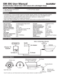
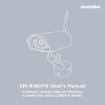
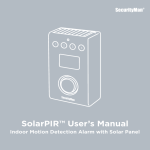
SM-GSMdialer User’s Manual
Quad-Band GSM Dialer (850/900/1800/1900MHz)
with LED for Air-Alarm Series
© Copyright 2012
This manual is furnished under license and may be used or copied only in
accordance with the terms of such license. Except as permitted by such license,
no part of this publication may be reproduced, stored in a retrieval system, or
transmitted, in any form or any means, electronic, mechanical, recording, or
otherwise, including translation to another language or format, without the
prior written permission of SecurityMan. The content of this manual is furnished
for informational use only, is subject to change without notice, and should not
be construed as a commitment by SecurityMan. SecurityMan Inc assumes no
responsibility or liability for any errors or inaccuracies that may appear in this book.
FCC Information
This device complies with part 15 of the FCC Rules. Operation is subject to the
following two conditions:
(1) This device should not cause harmful interference.
(2) This device must accept any interference received, including interference that
may cause undesired operation. Operation of this equipment in a residential area
is likely to cause interference in which case, the user at his or her own risk and
expense will be required to correct the interference.
Warranty
SecurityMan Inc warrants that this product will be free from defects in title,
materials and manufacturing workmanship for a period of one year or otherwise
specified on the product packaging. This limited warranty shall commence from
the date of purchase. SecurityMan products warranty is not transferable and is
limited to the original purchaser. If the product is found to be defective then, as
your sole remedy and as the manufacturer’s only obligation, SecurityMan will
repair or replace the product. This warranty shall not apply to products that have
been subjected to abuse, misuse, abnormal electrical or environmental conditions,
normal wear and tear, or any condition other than what can be considered normal use.
Warranty Disclaimers
SecurityMan Inc, makes no other warranties, express, implied or otherwise,
regarding this product, and specifically disclaims any warranty for merchantability
or fitness for a particular purpose. The exclusion of implied warranties is not
permitted in some states and the exclusions specified herein may not apply to you.
This warranty provides you with specific legal rights. There may be other rights
that you have which vary from state to state.
Limitation of Liability
The liability of SecurityMan Inc, arising from this warranty and sale shall be limited
to a refund of the purchase price. In no event shall SecurityMan be liable for costs
of procurement of substitute products or services, or for any lost profits, or for any
consequential, incidental, direct or indirect damages, however caused and on any
theory of liability, arising from this warranty and sale. These limitations shall apply
not withstanding any failure of essential purpose of any limited remedy.
For Tech Support Call: 888-977-3777
SecurityMan
4601 E. Airport Drive
Ontario, CA, 91761, USA
Tel: 909-230-6668
Fax: 909-230-6889
Email: [email protected]
Website: www.securitymaninc.com
Copyright 2012 by SecurityMan v1.0
Table of Contents
Introduction
1
Features
1
Important
2
Restrictions
2
Conditions
4
Package Contents
5
Product Basics
6
Front Panel
6
Back Panel
8
Installation
9
Programming
13
Operation
13
Specifications
14
Introduction
Thank you for choosing SecurityMan products. The SM-GSMdialer is
designed for the SecurityMan Air-Alarm (wireless alarm system) users
who do not have a land line and still want to be alerted for any alarm
event. The SM-GSMdialer is compatible with “Pay as you go” and
Contract SIM cards (not included) from all the major mobile service
providers. This allows you to choose between varieties of rate plans
and also to select the network that provides the best coverage to the
desired location, giving you the peace of mind that no matter what
happens at a remote location, you will always know instantly. In addition
to alarm notifications, it can also be connected to any phone hand-set
and used for everyday incoming and outgoing phone usage.
Features
• Supports quad-band GSM SIM card with 850/900/1800/1900MHz
frequencies
• Two Ni-MH 4.8v 600mAh rechargeable back up batteries
(up to 4 hours standby)
• Four LED notifications: GSM signal, call pick-up, low power,
and SIM problem
• GSM antenna with magnetic base and 9.5 ft cable
(for accurate positioning)
• Cable management slots and GSM anchor guidance card for
easy installation
• Two “telephone-out” ports
(alarm host and telephone hand-set for regular call usage)
• Backup battery power ON/OFF switch
1
Important
This guide provides important information on the use and operation
of your SM-GSMdialer. Please read all the information carefully prior
to using the product for the best performance and to prevent any
damage/injuries or misuse of the device(s). Customers are entitled
to have read through this complete user’s manual before using the
SM-GSMdialer. Any unapproved changes or modifications will void
your warranty. Please ensure to have a complete understanding of the
following restrictions.
Restrictions
When using this product, the safety precautions below must be taken
to avoid possible legal liabilities and damages. Retain and follow all
product safety and operating instructions. Observe all warnings in
the product operating instructions. To reduce the risk of bodily injury,
electric shock, fire and damage to the equipment, observe the following
precautions.
• DO NOT places this product too close to medical equipments.
1. Radio waves might potentially cause breakdown of medical
electrical equipments and thus cause incidents.
2. Place the product at least 22cm from the heart pacemaker.
Radio wave potentially influences heart pacemaker and thus leads
to respiratory disturbance.
• DO NOT uses this product to monitor equipments or activities that are
relevant to one’s privacy. Monitoring one’s private activities without
consent is illegal and this product is not designed and manufactured
for these purposes.
2
• DO NOT use this product to carry out any illegal activities.
SecurityMan shall not be responsible for any consequences of illegal
conducts made by users.
• DO NOT put the plastic package bags in reach of children or babies.
Young children can choke on these items if they put them into their
mouths.
• DO NOT plug the AC adapter into the outlet in improper situations.
• Plugging in an AC adapter with wet hands might cause electric shock.
• Plugging in the AC adapter unsteadily might cause fire or electric
shock.
• DO NOT cover the AC adapter when it is connected to an outlet, place
the adapter near heaters, or put it on the floor which is equipped with
a heater. The above mentioned operation might cause fire or incidents.
• DO NOT use it aboard; please abide by the airway’s provision. It might
influence communication aboard and the flying apparatus if departing
from the airway’s regulation. This will result in accident, possible death
and severe physical hurt.
• DO NOT disassemble or repair the dialer or any other relevant
peripheral equipment s on your own. Improper disassembly might
cause damage to the product or the peripheral equipment.
3
Conditions
Please read the following messages to make sure your working
environment is suitable.
• The temperature should be kept between: -10°C ~ 70°C, Humidity:5% ~ 95%
• Avoid putting the product in places where temperature or humidity
may change rapidly.
• Keep it dry, dustless and avoid lens exposure in direct sunlight.
• Keep product away from heat sources such as electric heaters.
• Do not place product near any strong magnetic objects
• Do not disassemble the product.
• Do not shake or strike the product.
• Please obey the local government’s environment protection policy.
4
Package Contents
SM-GSMdialer
1 x AC Adapter
4x Dry Wall Screws
Antenna
1 x Phone Cable
Anchor Guidance
Antenna Bracket
User’s Manual
5
Product Basics
Front Panel
Call Pick Up
Low Power
GSM Signal
SIM Problem
GSM Signal
The red GSM Signal LED represents the signal between the dialer and
the GSM network.
Fast Flash: GSM signal is weak, or the SIM card cannot be recognized.
Slow Flash: Normal working status.
Call Pick Up
• Outgoing Calls: The SM-GSMdialer will beep once and the ”Call Pick
Up” LED will stay on solid red whenever an outgoing call is being
made, giving an audible and visual notification to anyone who walks
by that the phone is in use.
6
• Incoming Calls: During an incoming call event, the SM-GSMdialer will
click (relay sound) once for every ring and the ”Call Pick Up” red LED will
flash until the phone is answered or the call is no longer coming through.
Low Power
During power failure, the Low Power LED will stay “Solid Red” only
when the batteries have less than 7V of charge remaining indicating
that the internal backup batteries need to be charged. When the Low
Power red LED comes on the GSM dialer will continue to functions
normal for 20 minutes from the time the LED light comes on.
SIM Problem
The SIM Problem red LED stays ON only if there is no SIM card inserted
into the SM-GSMdialer, inserted card is not active, or an error occurs
during normal operation. If an error should occur during normal
operation, please power cycle the unit by switching it to the off
position and disconnecting it from the power outlet.
NOTE: Please contact your SIM card provider if the error persists.
IMORTANT: The SIM problem LED will only go on when a SIM card
has become deactivated (no service), so please make sure to check
your balance frequently when using pay as you go/pre-paid services. Please keep in mind that the average grace period for none payment
or zero balance deactivation is about 1 month and it’s only at this point
that the SIM problem LED will turn on.
7
Back Panel
GSM Antenna
Cable Management Slots
Mounting Holes
SIM Card Slot
SIM
TEL OUT
Backup Battery ON/OFF
TEL OUT to Alarm Host
TEL OUT
Power
TEL OUT to Phone/
Alarm Host
Power
The Power socket is used to provide power to the SM-GSMdialer. Please
insert the supplied AC Power adapter to the socket located below the
backup battery on/off switch on the back of the GSM dialer.
Backup Battery ON/OFF
The Backup Battery ON/OFF switch is used to enable (ON) or disable
(OFF) the SM-GSMdialer to run of the internal backup batteries in an
event that the power should go out.
Mounting Holes
The mounting holes are used to mount the SM-GSMdialer to the wall.
NOTE: Please use the supplied “GSMdialer Anchor Guidance” card for
accurate positioning.
Cable Management grooves
The cable management grooves are used to secure and hold the cables
in place.
8
SIM Card Slot
Insert your pre-paid or contract SIM card into the SIM Card Slot (face
up) with the gold contacts of the SIM card facing the metal contacts of
your SM-GSMdialer.
GSM Antenna
The treaded insert located at the top of the SM-GSMdialer is where the
supplied antenna must be screwed on to.
NOTE: Please extend the 9.5ft antenna cable when necessary to
guarantee the best reception.
TEL OUT
The SM-GSMdialer is equipped with 2 Tell OUT ports.
1. Connects directly to the TEL IN port of your SecurityMan Wireless
Security systems host (SM-8088E/T).
2. Connects to a phone handset for normal phone usage (making
or receiving calls) or to your SecurityMan Wireless Security
systems host.
NOTE: The alarm host (SM-8088E/T) also has a TEL OUT port that can
also be used to connect you phone handset.
Installation
Prepare the location where you will be mounting the SM-GSMdialer by
using the GSM anchor guidance card to pre-drill the mounting holes as
shown below (use the green dry wall inserts when applicable).
9
Remove the rectangular plastic cover located on the back side of the
SM-GSMdialer and insert your pre-paid or contract SIM card (face up)
into the SIM card slot as illustrated below.
NOTE: Please make sure you are using an active SIM card and that there
is sufficient funds available (if using pay as you go/pre-paid services).
Connect your phone cables from the “TEL OUT” port to “TEL IN” port
of your existing SecurtiyMan Air-Alarm Host (SM-8088E/T). The second
“TEL OUT” port is for another Air-Alarm Host or phone handset as
shown below.
SM-GSMdialer Back Panel
SIM
Air-Alarm Back Panel
TEL OUT
TEL OUT
TEL OUT
TEL IN
TEL IN
TEL OUT
10
NOTE: Please make sure to run the excess cable through the cable
management groves so that the unit can sit flush on the wall when
mounted. The Air-Alarm Host also has a “TELL OUT” port that can also
be used to connect a telephone handset.
Move the Backup Battery on/off switch to the ON position located at
the back of the GSM dialer. Then connect the provided power adapter to
the Power socket of the GSM dialer and the other end into an electrical
power outlet as illustrated below. Run any excess cables through the cable
management groves so that the unit can sit flush on the wall when mounted.
11
Secure the rectangular plastic cover (removed page 11) as illustrated below.
Match the SM-GSMdialer mounting holes over the two secured screws
(page 11) and then push in to overlap and down to secure.
Thread the SMA antenna end of the antenna cable through the circular
hole on the mounting bracket and let the antenna cable hangs down
towards the GSM dialer as illustrated below.
12
Place the magnetic base of the antenna on the metal plate of the
bracket to secure. Mount the antenna mounting bracket (included) to
a desired location (preferred to mount higher up for best reception)
using the two dry wall screws provided to secure the bracket in place
as illustrated below. Please remember to aligned the antenna cable
along the base opening cut of the antenna bracket before fastening
the mounting screws.
13
Finally, twist in the SMA end of the antenna cable to the GSM dialer
antenna threads to secure. Clamp or tied down any loose wires (ties/
clamp not included). as illustrated below.
NOTE: Please extend the 9.5ft antenna cable when necessary to
guarantee the best reception. The antenna magnetic base cannot
stand on its own, please attached the base to metallic materials or
use the antenna mounting bracket included.
14
Programming
Ring Control:
Ring control is use to setup the number of rings the handset will ring for.
GSM dialer allows two options for ring control. To setup the number of
rings, please make sure that the handset is connected to the GSM dialer.
To setup 4 rings for voice mail, pick up the handset and press:
* # 9999 3 0 [After pressing * # follow by a beep, input 9999 follow by a
beep, input 3 follow by a beep, input 0 follow by a beep sound. If setup
failed, it beeps twice and exit]
To setup 9 rings to by-pass the voice mail, pick up the handset and press:
* # 9999 3 1 [After pressing * # follow by a beep, input 9999 follow by a
beep, input 3 follow by a beep, input 1 follow by a beep sound. If setup
failed, it beeps twice and exit. When setup to 9 rings, it allows the GSM
dialer to delay the numbers of rings in order to remote ARM and remote
DISARM of Alarm Host when using the dialer with the Air-Alarm Host
series.]
IMPORTANT NOTICE: 9 rings is the GSM dialer system default setting
intended for our Air-Alarm series integration to remote ARM and remote
DISARM. When setup to 9 rings meaning the Air-Alarm series Host will
pickup after 9 rings, you may encountered 1 regular ring tone and 8 prolong ring tones to complete 9 rings overall, this is normal.
GSM dialer integrating with the Air-Alarm series
To Remote ARM:
After a 30-sec period of dialing in to the GSM dialer, there will be: a beep
> enter programming password of host (be sure to wait 3 seconds after
15
each digit password inputted) > beep > enter 1 > beep, and the host will
then automatically hang up after the last beep to successfully complete
the operation.
To Remote DISARM:
After a 30-sec period of dialing in to the GSM dialer, there will be: a beep
> enter programming password of host (be sure to wait 3 seconds after
each digit password inputted) > beep > enter 0 > beep, and the host will
then automatically hang up after the last beep to successfully complete
the operation.
NOTE: Please wait for a period of 3 seconds in between each button
pressed to ARM and DISARM the Alarm Host.
Volume Control:
This feature allows you to set the volume level for incoming and outgoing
calls. This is a 4 part command and requires a handset to complete. You
will hear a single “beep” at the end of each successful command entry
and a double “beep” if entered incorrectly.
• Pick up the handset and press:
* # 9999 2 X
[Enter 1 through 9 for “X” to set the desired volume level, system default is 8]
16
Operation
How to make a phone call
Pick up the phone and press the “TALK” button on the hand set, at this
time the SM-GSMdialer will beep once and the ”Call Pick Up” LED will stay
on giving an audible and visual notification to anyone who walks by that
the phone is in use. Input the phone number to be dialed and the SMGSMdialer will begin to dial out 3-4 seconds after the last digit is pressed.
NOTE: The SM-GSMdialer starts to dial 3-4 seconds after the last
number is pressed, so make sure not to pause for more than 3 seconds
in between numbers when attempting to make a phone call. For 6.0GHz
cordless phone users, the GSM dialer requires the SecurityMan Alarm
Host series to be connected in order to operate the 6.0GHz cordless
phone.
How to answer a call
Answer a call in the same manner that you would a normal land line
phone. During an incoming call event, the SM-GSMdialer will click (relay
sound) once for every ring and the ”Call Pick Up” LED will flash until the
phone is answered or the call is no longer coming through.
Air-Alarm host setup
Connect a phone line from one of the “TEL OUT” ports of the SMGSMdialer to the “TEL IN” port of the alarm host.
NOTE: Remotely arming/disarming the host will require you to disable
your SIM cards voice mail (if applicable). Please contact your carrier for
information on how and if this can be done.
**Please refer to your Air-Alarm user’s manual for instructions on how
to add phone numbers to the host or you can visit our website to
download a digital copy of your Air-Alarm user’s manual by visiting our
website at: http://www.securitymaninc.com/?page_id=625
17
Specifications
GSM Frequency
GSM Emitting power
Static Current
Power Supply
Active Current
Backup Battery
Standby time
Full Charging Time
Operation Condition
Telephone Port
850/900/1800/1900MHz
2W
<60mA (when not charging)
Input: AC 110~240V, Output: DC 12V 1.0A
<350mA
2 x 4.8V 600mAh (Ni-MH)
4 hours (full load)
8 hours
14°F ~ 158°F, Humidity: 5% ~ 95%
2 TELL OUT
18