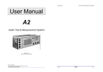
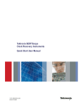
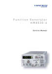
1
Multimeter HM 8012 German .................................. 3 English ................................... 21 4¾-Digit Programmable Multimeter HM8012 ..................... 22 Operating Manual ........................... General information ....................... Safety ............................................. Symbols as marked on equipment Operating conditions ...................... Warranty ......................................... Maintenance .................................. Operation of the module ............... 24 24 24 24 24 24 24 25 HM 8012 Front panel commands .. Mode selection .............................. Choice of range .............................. Measurement value display ........... Measurement inputs ..................... Voltage measurements .................. Input impedance in the V range .... 25 27 27 27 27 28 28 Subject change without notice Current measurement ................... AC voltage measurement .............. Resistance measurements ............ Protection against overloads ......... Crest factor .................................... Diode test ....................................... Temperature measurements ......... Decibel measurements .................. Equipment remote control ............ Function commands ...................... Calibration commands ................... Function Test .................................. Measurement equipment used ..... Adjustment procedure ................... 28 28 28 28 29 29 29 30 30 30 32 32 32 33 WDM8012 SOFTWARE .................... 34 General information regarding the CE marking ........... 35 21 4¾-Digit Programmable Multimeter HM 8012 50,000 counts, 4¾-digits Auto-Range, 42 measurement Ranges, Between 3 to 6 masurements/sec Offset of any value as reference point True RMS Measurement of AC or AC + DC Basic Accuracy 0.05% Ω Max. Resolution 10µV, 0.001dBm, 10nA and 10mΩ Ω (0.5V and 5V) Input Resistance > 1GΩ Communication by RS-232 link on front panel Control of all functions with user friendly software HM 8012 is a programmable digital multimeter with 8 primary measurement functions including 42 ranges. Autoranging provides optimum resolution of an unknown input magnitude. The 5 digit bright display will represent a measured magnitude of up to 50,000 points. The absolute resolution Ω at a basic obtained is 10µV, 10nA or 10mΩ dc accuracy of 0.05%. Input resistance Ω in the VDC mode allowing exceeds 1GΩ precise measurement on high source resistance. True RMS measurements of AC voltage/current even of distorted waveforms are made up to 100kHz and AC+DC values can be evaluated. The multimeter is capable of making temperature measurement with a Pt100 sensor in °C or °F up to 0.1° resolution. At diode measurements, the HM8012 shows the junction voltage of the DUT, while a constant current is supplied. Analyses of audio and communication circuits is easy, because you can read in dB with a resolution of 0.01dB. Offset compensation is employed to eliminate the effects of any line resistance influencing 22 resistor measurements. Any value can be set as a new reference point (ZERO adjustment). Calibration constants are stored in a EEPROM for each measurement range. A softwarecontrolled calibration routine allows a complete instrument calibration without any manual adjustments. All instrument functions can be controlled via a RS-232 standard interface, with the provided software under Windows ® . Gradients can be recorded over a given time and can processed under Excel®. Protection circuits ensure safe operation of HM 8012, protecting the equipment at the limit values as indicated against any damage resulting from manipulation errors. The connection terminals are protected (safe terminals). The HM 8012 digital multimeter is an appropriate measurement instrument whenever the value obtained has to be highly accurate, very stable in the long term and easy to use. The programming feature of the HM 8012 permits integration in an automatic test environment as a system multimeter. Subject change without notice Specifications Resistances Reference temperature: 23°C ± 1°C Measurement range: 500 Ω, 5 kΩ, 50 kΩ, 500 kΩ, 5 MΩ, 50 MΩ Resolution: 10mΩ, 100mΩ, 1Ω, 10Ω, 100Ω, 1kΩ Accuracy: ± (0.05%rdg + 0.004%fs + 50mΩ) ranges 5mΩ and 50MΩ: ± 0.3%rdg+0.004%fs) Input protected to max. 300 Vrms DC voltages: Measurement ranges: 500mV, 5V, 50V, 500V, 1000V Resolution: 10µV, 100µV, 1mV, 10mV, 100mV Accuracy: 5V, 500V, 1000V: ±0,05% v.M.1) +0,002% v.E 2) 500mV, 50V: ± 0,05% v.M.1) + 0,004% v.E2) Max. input voltage: for 50V-, 500V- und 1000V-ranges: 1000Vs for 500mV- and 5V-ranges: 300Veff Input impedance: for 50V-, 500V- and 1000V-ranges: 10MΩ//90pF for 500mV- and 5V-ranges: >1GΩ//90pF Input current: 20A max. (30 sec.) Common mode rejection ratio ≥100dB (50/60Hz ± 0.5%) Serial mode rejection ratio ≥60dB (50/60Hz ± 0.5%) dB Mode Precision: Resolution: ±(0.02dB+2digits) (display>-38.7dBm) 0.01dB above 18% of rating. DC current: Measurement ranges: 500µA, 5mA, 50mA, 500mA, 10A Resolution: 10nA, 100nA, 1µA, 10µA, 1mA Accuracy: 0.5-500mA: ± (0.2%rdg + 0.004%fs) 10A: ±(0.3%rdg + 0.004%fs) AC voltages: Measurement ranges: 500mV, 5V, 50V, 500V, 750V Resolution: 10µV, 100mV, 1mV, 10mV, 100mV Accuracy 0.5-50V: at 40Hz-5kHz: ± (0,4% v.M. + 0,07% v.E.) at 20Hz-20kHz: ± (1% v.M. + 0,07% v.E.) 500V und 750V: at 40Hz-1kHz: ± (0,4% v.M. + 0,07% v.E.) at 20Hz-1kHz: ± (1% v.M. + 0,07% v.E.) Max. input voltage: for 50V-, 500V- and 1000V-ranges: 1000Vs for 500mV- and 5V-ranges: 300Veff Input impedance AC mode: 1MΩ // 90pF AC + DC mode: 10MΩ // 90pF Bandwidth at - 3dB: 80kHz typical dB Mode: (20Hz-20kHz) Accuracy: -23.8dBm to 59.8dBm; ± 0.2 dBm CMRR: ≥60dB (50/60Hz ± 0.5%) Peak factor: 7 max. AC current Measurement ranges: 500 µA, 5 mA, 50 mA, 500 mA, 10 A Resolution: 10nA, 100nA, 1µA, 10µA, 1mA Accuracy: 0.5-500mA: 40Hz - 5kHz ± (0.7%rdg + 0.07%fs) 10A: ± (1%rdg + 0.07%fs) Temperatures: 2-wires resistance measurement with linearization for Pt 100 sensors as per standard EN60751 Range: - 200°C to + 500°C Resolution: 0.1°C Measurement current: approximately 1 mA Display: in °C, °F Accuracy: ± 0.1°C from - 200°C to + 200°C ± 0.2°C from 200°C to 500°C (except for sensor tolerance) Temperature coefficient: (Reference 23°C) V= 500mV, 50V 30ppm/°C 1000V range 80ppm/°C other ranges 20ppm/°C V~ 750V range 80ppm/°C other ranges 50ppm/°C mA all ranges 200ppm/°C mA- all ranges 300ppm/°C Ω 5 MΩ, 50 MΩ ranges 200ppm/°C other ranges 50ppm/°C Measurement current for resistance measurement 500Ω/5kΩ range 50kΩ range 500kΩ range 5/50MΩ range 1mA 100µA 10µA 100nA Measurement voltage for resistance measurement 10 V typical for open inputs; depending on value of resistance to be measured. Negative polarity of measurement voltage is across common terminal. Voltage drop for current measurements 10A range 500mA range Other ranges Operating conditions: 0.2 V max. 2.5 V max. 0.7 V max. + 10 °C to + 40 °C max. relative humidity 80%. Power supply (only HM 8012): + 5V / 300mA ~26 V / 140 mA Size (L x H x D): 135 x 68 x 228 mm (without flat 22-pole connector) Weight: approx. 500g AC + DC measurements Same as AC + 25 digits 1) rdg = reading; 2) fs = full scale Subject change without notice 23 General information The operator should not neglect to carefully read the following instructions and those of the mainframe HM8001, to avoid any operating errors and to be fully acquainted with the module when later in use. After unpacking the module, check for any mechanical damage or loose parts inside. Should there be any transportation damage, inform the supplier immediately and do not put the module into operation. This plug-in module is primarily intended for use in conjunction with the Mainframe HM8001. When incorporating it into other systems, the module should only be operated with the specified supply voltages. Safety This instrument has been designed and tested in accordance with IEC Publication 1010-1, Safety requirements for electrical equipment for measurement, control, and laboratory use. It corresponds as well to the CENELEC regulations EN 61010-1. All case and chassis parts are connected to the safety earth conductor. Corresponding to Safety Class 1 regulations (threeconductor AC power cable). Without an isolating transformer, the instruments power cable must be plugged into an approved three-contact electrical outlet, which meets International Electrotechnical Commission (IEC) safety standards. Warning! Any interruption of the protective conductor inside or outside the instrument or disconnection of the protective earth terminal is likely to make the instrument dangerous. Intentional interruption is prohibited. The instrument must be disconnected and secured against unintentional operation if there is any suggestion that safe operation is not possible. This may occur: if the instrument has visible damage, if the instrument has loose parts. if the instrument does not function, after long storage under unfavourable circumstances (e.g. outdoors or in moist environments), Symbols as Marked on Equipment ATTENTION refer to manual. DANGER High voltage. 24 Protective ground (earth) terminal. Operating conditions The ambient temperature range during operation should be between +10°C and +40°C and should not exceed -40°C or +70°C during transport or storage. The operational position is optional, however, the ventilation holes on the HM8001 and on the plug-in modules must not be obstructed. Warranty HAMEG warrants to its customers that the products it manufactures and sells will be free from defects in materials and workmanship for a period of two years. This warranty shall not apply to any defect, failure or damage caused by improper use or inadequate maintenance and care. HAMEG shall not be obliged to provide service under this warranty to repair damage resulting from attempts by personnel other than HAMEG representatives to install, repair, service, or modify these products. In order to obtain service under this warranty, customers have to contact and notify their distributor. Each instrument is subjected to a quality test with ten-hour burn-in before leaving the factory. Practically all early failures are detected by this method. In the case of shipments by post, rail, or carrier it is recommended to preserve the original packing carefully. Transport damages and damage due to gross negligence is not covered by warranty. In the case of a complaint, a label should be attached to the housing of the instrument that describes briefly the faults observed. If at the same time the name and telephone number (dialing code and telephone or direct number or department designation) is stated for possible queries, this helps towards speeding up the processing of warranty claims. Maintenance Various important properties of the module should be checked carefully in certain intervals to ensure that all signals and measurement results are displayed with the accuracy on which the technical data are based. When removing the case detach mains/line cord and any other connected cables from case of the mainframe HM8001. Remove both screws on rear panel and, holding case firmly in place, pull chassis forward out of case. When later replacing the case, care should be taken to ensure that it properly fits under the edges of the front and rear frames. After removal of the two screws at the rear of the Subject change without notice module, both chassis covers can be lifted. When reclosing the module, care should be taken that the guides engage correctly with the front chassis. Operation of the module Provided that all hints given in the operating instructions of the HM8001 Mainframe were followed, especially for the selection of the correct mains voltage, start of operation consists practically of inserting the module into the right or left opening of the mainframe. The following precautions should be observed: Before exchanging the module, the mainframe must be switched off. A small circle (o) is now revealed on the red power button in the front centre of the mainframe. If the BNC sockets at the rear panel of the HM8001 unit were in use before, the BNC cables should be disconnected from the basic unit for safety reasons. Slide in the new module until the end position is reached. Before being locked in place, the cabinet of the instrument is not connected to the protective earth terminal (banana plug above the mainframe multipoint connector). In this case, no test signal must be applied to the input terminals of the module. HM 8012 Front panel commands (1) DISPLAY (7-segment LED + LED) The digital display shows the measurement value with 4 3/4 digit resolution, in which the largest figure is used up to “5”. It will also display various warning messages. The measurement value will be displayed with decimal points and polarity sign. For DC measurement, a minus sign will appear in front of the figures when the positive polarity of the measured value is connected to the COM input (7). (2) (LED) Indicator denoting validation of the audible continuity test signal. When used as an Ohmmeter, the audible signal triggers when the measured resistance value is less than 0.1% of the range or 50 counts. For other functions, the indicator is hidden. (4) A (10A) (safety terminal for 4 mm banana plugs) Connection (high potential) for DC and AC current measurements in the 10 A range in conjunction with the COM input (7) (low potential). The input is not fuse-protected. Current in excess of 10 A (max. 20 A) must not be applied for a period exceeding 30 s, otherwise the internal measurement resistor thermal device will blow. (5) mA/µA (safety terminal for 4 mm banana plugs) Connection (high potential) for DC and AC current measurements up to 500 mA in conjunction with COM (7) input (low potential). The input is fuseprotected. This input is opened when functions other than mA/µA are being used. (3) BEEP (pushbutton) Pushbutton for activating the audible signal. Subject change without notice 25 (6) HOLD (LED) Indicator denoting that the displayed value has been frozen. The function can be activated using key (10). Deactivation is by pressing the HOLD/OFFSET key. (7) COM (safety terminal for 4 mm bana plugs) The COM terminal (low potential) is the common connector for all the measurement functions to which the potential close to the ground of the measured quantity will be applied. CAUTION! For safety reasons, the voltage across this terminal compared to the case (guard wire, ground) shall be 500 V at most. (8) OFFSET (LED) Indicator denoting that the displayed value is a relative measurement. The displayed value corresponds to the input value less the value present on the display during initial action on the HOLD/ OFFSET key (10). Activate this function by means of a second press on the HOLD/OFFSET key. Ω/T°/dB/ (9) V/Ω (safety terminal for 4 mm banana plugs) Connection (high potential) for measurements of voltages, resistances, temperatures and diode junctions in conjunction with the COM input (7) (safety terminal). CAUTION! For safety reasons, the voltage across this terminal compared to the case (guard wire, ground) shall be 1,000 V at most. (10) HOLD/OFFSET (pushbutton) Pushbutton for validating the HOLD or OFFSET functions. Pressing the key the first time will freeze the front panel display. The HOLD indicator (6) then comes on. The AUTO, AC-DC, BEEP, and keys are inoperative. 26 A second press gives access to the relative mode. The value memorized by the HOLD function is then subtracted from each measurement before being displayed. The OFFSET indicator (8) comes on. A third press will freeze the relative value. The HOLD (6) and OFFSET (8) indicators come on. A fourth press will delete the HOLD and OFFSET mode. NOTE: When the HOLD/OFFSET mode is engaged, pressing the or key will provoke return to the normal mode. Further, the manual mode is set on for HOLD and OFFSET functions. (11) (pushbutton) Pushbutton for changing to lower range. On each press, the new range is displayed fleetingly on the display in code form (L1 for lowest range, L2 for second range, etc.). (12) (pushbutton) Pushbutton for changing to higher range. Each time pressed, the new range will be displayed fleetingly on the display in code form (L1 for lowest range, L2 for second range, etc.). (13) RS-232 (DB9) Female DB9 connector intended for serial communication. (14) AUTO (LED) Indicator signalling that the multimeter is in AUTOMATIC mode. In this mode, action on keys (12) and (13) is inoperative. (15) AUTO (pushbutton) Pushbutton for switching the AUTO range selection to the MANUAL range selection and vice versa. In MANUAL mode, the choice of range is left to user initiative using the keys (12) and (13). Subject change without notice (16) Unit display zone (LED) This zone contains a display of the measurement units. It also identifies the function selected by pressing the (18) or (19) key. (17) AC-DC (pushbutton) This key is used for selecting the measurement mode (DC, rms AC or rms AC + DC). Indicators below indicate the measurement mode: DC: measurement of DC voltages AC: measurement of RMS AC voltages DC + AC: measurement of RMS AC+DC voltages. (18) (pushbutton) Pushbutton for selecting the next function. (19) (pushbutton) Pushbutton for selecting the previous function. On startup, the unit switches automatically to the DC voltmeter, MANUAL mode function and 1000-VoltRange. Choice of range In manual mode,theand keys are used for switching between the various measurement ranges. The measurement ranges are split into decades. After each range change, a code appears indicating the new range being used. This code is in LX form, where X is a value that may vary from 1 to 6 depending on the range and function and L1 is the lowest range. During measurements of unknown voltages or currents, first choose the highest measurement range, then switch to the range giving the most favorable display. Change to the higher range is obtained when the value exceeds 51,000 counts. Change to the lower range is obtained when the value drops below 4,900 counts. It is possible to know which range has been selected by the unit by temporarily deactivating the AUTO mode so that the range indication code appears fleetingly. Measurement value display Choice of multimeter functions Beginning in Volt-Range (V) by using the keys (19) and (18) you can step through all the multimeter functions one by one, in following order: DC or AC voltages. Input on the V/Ω/T°/dB and COM connectors. The measurement of DC or AC voltages in decibels (reference 1mW/600Ω). Input to V/Ω/ T°/dB and COM connectors. DC or AC current up to 500 mA. Inputs on mA/ µA and COM connectors. DC or AC current, 10 A range. Inputs on the A and COM connectors. Resistors. Inputs V/Ω/T°/dB and COM connectors. Temperature in degrees Celsius. Connection of probe to V/Ω/T°/dB and COM connectors. Temperature in degrees Fahrenheit. Connection of probe to V/Ω/T°/dB and COM connectors. Diode test. Inputs on V/Ω/T°/dB and COM connectors. On each press, the new function is indicated by an LED corresponding to the unit of the quantity to be measured. It is possible to move from one function directly to any other function by a successive series of pressings. Mode selection For current and voltage modes, the AC-DC key is used for choosing between DC voltage measurement, AC or AC + DC true rms voltage measurement. Subject change without notice Measurement values are represented by 7 segment LED’s display associated with one LED for the negative sign. The maximum value of the 1st digit is 5: this corresponds to a 4 3/4 digit display with a 50,000 counts measurement capacity. A minus sign appears in front of the figures when, during DC measurements, the positive polarity of the measured value is on the COM terminal. With the inputs short-circuited, the display indicates (depending on the measurement range) value zero ± 2 digit. When the range is overrun, the display shows “OFL” and an audible beep is emitted repeatedly if it is selected. For the resistance measurement function, the exceeding of the capacity (> 50MΩ) generates the “OPEN” message. If the multimeter is not connected to a circuit, the display indicates random values due to the very high input impedance for ranges of 500mV and 5V. Measurement inputs HM8012 has four safety terminals with which, when using appropriate measurement cables (e.g. HZ15), spurios measurements are totally ruled out. As a safety measure the measurement cables should be checked periodically for insulation faults and, when necessary, be replaced. The “COM” terminal (black) is common to all the measurement ranges. The potential close to ground of all the measurement quantities should be applied to this terminal. The input mA/µA (blue) and A (blue) is intended only for current measurements, whereas the input V/Ω/T°/dB is designed for all other measurements. Each terminal is appropriate to receive 4 mm banana plugs. 27 Voltage measurements The maximum input voltage of HM 8012 is 1000V DC when the COM terminal is to ground potential, i.e. by connecting HM 8012 to the object to be measured, the sum of the measurement voltage and that of the COM terminal with respect to ground shall not exceed 1000V DC. In this case, the maximum voltage value between the COM terminal and ground is 500V DC. For AC voltages, the true rms value of the input voltage will be measured, and the DC component eliminated in AC mode. If possible, the COM terminal shall be connected directly to ground or to the point of the measurement circuit having the lowest potential. The 0.5 V and 5 V voltage measurement ranges are protected from input voltages to 300 V rms; all the other ranges are protected to 1000 V DC. During measurements on circuits using inductive components, inadmissible high voltages may appear when the circuit is opened. In such cases, take steps to prevent the destruction of HM8012 by inductive voltages. therefore not circulate through HM8012 continuously. The maximum current measurement time >10A (max. 20A) is 30 sec. For this function, the AUTO mode is inhibited because there is only one range. AC voltage measurement The instrument measures the true rms value of the input voltage with or without its DC component. To measure low voltages, or in the event of high noise, it is possible to use a shielded cable. Take into account the input impedance of the multimeter. It is 1MΩ in the AC mode and 10MΩ in the AC + DC mode. In addition, there is a slight measurement difference between these two modes due to the input circuits. If AC measurements without a DC component are to be made, it is preferable to use the straight AC mode. When the multimeter is used in AUTOMATIC mode, there can be continuous swinging between two ranges for frequencies above 30kHz or so, because of the frequency response difference of the two ranges. After some swings, the instrument goes into MANUAL mode. Resistance measurements To make the most of the excellent linearity of the measurement system, the input impedance for voltage measurements is very high for some ranges. For instance, this makes possible to perform accurate measurements on ranges of up to ± 5V, even when the internal impedance of the source to be measured is high. For instance, for the 500mV range, an internal 5MΩ source resistance will induce a maximum error of 150µV. Indeed, switching to the 50V range will cause the input voltage to drop because of the input impedance of 10 MΩ which can cause the multimeter to switch to the lower range and so on. After some swings, the instrument goes into MANUAL mode. For resistance measurements, connect the object to be measured between the COM terminal and the V/Ω/T°/dB terminal. There is a DC voltage across the connection terminals. Accordingly, only voltage-free objects need to be measured because the voltages in the measurement circuit will distort the result. In the case of low resistance measurements, the OFFSET key can be used to compensate, where applicable, for measurement cord resistance. For high resistance measurements, it is advisable to place the resistance to be measured as close as possible to the measurement terminal or to use a shielded measurement cable connected to ground. On startup, simultaneously pressing MODE and OFFSET will eliminate the correction of the HZ15 measurement cord resistance. Current measurement Protection against overloads For current measurements, the connection of the object to be measured is made across the mA/µA terminal or to the A terminal for currents of up to 10 A. The HM8012 should be connected to the circuit whose potential with respect to ground is lowest. For safety reasons, the COM terminal must not exceed 500Vp with respect to ground. Current ranges are protected by a fuse against overloads of up to 500mA. If the fuse blows, the cause of the overload must first be eliminated and then the fuse can be replaced. See “Protection from overloads” paragraph for more details about fuse replacement. The 10A current measurement function is not fuse protected. Current in excess of 10A (max. 20A) must All the HM8012 measurement ranges are protected against various forms of overload. Precise indications are given in the technical characteristics. In general: during the measurement of unknown quantities, always begin with the highest measurement range and, from then on, switch ranges using optimum display. If HM8012 malfunctions, first eradicate the cause before going on to make the following measurement. If these safety limit values are exceeded, i.e. 1000 V DC or 750 V RMS , the OFL message will be displayed and the associated audible signal will sound. For an overrun exceeding 5% of the range, Input impedance in the DC range 28 Subject change without notice a fast audible signal will be heard and the input relay will open to prevent any damage to the equipment. The OFF message will be displayed. Resetting is by pressing the sort key. Changing fuse: to repair HM8012 after an overload in a current range, the fuse needs to be replaced. To do this, open the unit because the fuse can only be reached from the inside. In any case, only a fuse of the indicated type may be used; otherwise HM8012 could sustain damage and the technical characteristics of the current measurement ranges would no longer be maintained. Characteristics of fuse: 500 mA fast-blow, 250 V T = period duration t = pulse duration U = pulse voltage. Crest factor To evaluate complex or deformed signals, the determination of a true rms value is necessary. The HM8012 digital multimeter will allow the measurement of AC quantities with a display of the true AC or AC + DC value. The crest factor is important data for interpreting measurement values and for evaluating its accuracy. It is defined as the ratio between the peak voltage and the rms value of the signal. Crest factor = CF = Up/Ueff It is a measurement of the dynamic input voltage range of the AC converter and expresses the capability of processing measurement signals with a high peak value, without the converter entering into saturation. The HM8012 crest factor ranges from 1 to 7 (for additional measurement error of < 1%) and depends on the magnitude of the rms value of the signal to be measured. Figure 1 gives an additional error depending on the crest factor for a pulse type signal. To avoid saturation of the HM8012 input stages, make sure that the input signal peak value does not exceed 3 times the value of the range, or 1000 V. At the middle of the measurement range, the maximum crest factor is 6. The accuracy of the displayed value depends, among other things, on the rms value converter bandwidth. Complex signal measurements will barely be influenced when there are no harmonic components in the measurement signal placed outside the 100 kHz (- 3 dB) bandwidth of the converter. Additional error due to high crest factor Error ± (% of reading) CF 1-2 2-3 3-4 4-5 % 0.05 0.15 0.3 0.4 5-6 0.5 Another factor influencing the measurement precision is the duty cycle of the measurement signal. The crest factor in this relation becomes: CF = T/t Subject change without notice Accordingly, a rectangular signal having a duty cycle of 1% has a crest factor of 10. The minimum pulse duration should be approximately 10 µs. Diode test Choose the diode test function using (18) or (19) key. For diode measurements, connect the device under test (DUT) between the COM terminal and the V/Ω/T°/dB terminal. There is a DC voltage across the connection terminals. Accordingly, only voltage-free objects need to be measured because any additional voltages in the measurement path will distort the result. It is preferable to remove, if necessar y, any components connected to the semiconductor for precise results. It is possible to measure voltages up to 5 V. The maximum voltage that the equipment will supply is 10 V in an open circuit. If the cathode of the DUT is connected to the ground (COMterminal), the diode operates in its conducting mode. If the anode of the DUT is connected to ground, the diode operates in its reverse mode. For measurements on Zener-diodes, the anode of the device should be connected to ground. Take care when making measurements on sensitive circuits. The current supplied by HM8012 is 1 mA constant for this function. All keys except and HOLD/OFFSET are inactive for this function. Temperature measurements Choose the temperature measurement function (°C or °F) using (18) or (19) key. The temperature probe is connected between the COM terminal and the V/Ω/T°/dB terminal. The temperature probe is connected between the COM terminal and the V/Ω/ T°/dB terminal. Temperature measurement requires a temperature probe type Pt100 as per standard EN60751. The use of another probe is possible but can generate additional errors due to a different link cable resistance. All keys except and HOLD/OFFSET are inactive for this function. 29 After the instrument has been turned-on, the line resistance value of the temperature probe is automatically compensated. On starting, simultaneously pressing BEEP and OFFSET will eliminate probe cable resistance compensation (zero value). In all cases, compensation can be carried out by setting the probe to a temperature of 0 °C and using the OFFSET function. Note: Measurement of the temperature probe line resistance should be made on the same instrument used for temperature measurements. Only this procedure guarantees the specified measurement error. Decibel measurements Choose the decibel measurement function using (18) or (19) key. For decibel measurements, the unknown input voltage is connected between the COM terminal and the V/Ω/T°/dB terminal. The HM8012 is used for DC or AC voltage measurements in decibels. The 0 dB reference is defined for 1mW power in a 600 Ω load., i.e. a voltage of 0.7746V. The scale extends from –78 dBm to 59.8dBm. In a 50Ω-system, the reference voltage for 1mW power is 0.2236V. In a 75Ω-system, the reference voltage for 1mW power is 0.2739V. If decibel measurements are made on a 50Ωsystem, add 10.8dB to the displayed value. If decibel measurements are made on a 75Ω-system, add 9dB to the displayed value. The mathematical relationship is as follows: The instrument internal buffer includes only three characters, and there is no way of sending more than one command at a time. On reception of terminator <CR>, the equipment sends the character 19 (<DC3> ASCII) to indicate that the dialogue is suspended. As soon as it is possible to resume dialogue, the instrument sends character 17 (<DC1> ASCII). The commands are divided into five groups: Function commands These commands are used for choosing another magnitude to be measured and corresponding to the choice of FUNCTION key on the front panel. VO<CR> voltage measurement (VOLT) AM<CR> current measurement (A) MA<CR> current measurement (mA) OH<CR> resistance measurement DI<CR> diode test TC<CR> temperature measurement in °C TF<CR> temperature measurement in °F DB<CR> measurement in dB. For these commands, there is no error recovery provided for because it is normally possible to put the instrument in one of these states at any time. Mode commands Mode commands correspond to the “MODE” key on the front panel. DC<CR> AC<CR> switches the instrument to the DC measuring mode. switches the instrument to the AC measuring mode. switches the instrument to the AC + DC measuring mode. activates the continuity test beep. deactivates the continuity test beep. R= Reference resistance in Ω ; P0=1mΩ; V0 in V Sign consideration: A displayed value of –12dB is equivalent in 50Ω to: -12dB +10.8dB = -1.2dB AD<CR> Equipment remote control If the requested mode is not compatible with the current function (e.g.: sending the AC command while the instrument is measuring resistances), the instrument will indicate this by a beep in the same way as for the front panel control. In addition, the control error indicator is set (see command E7). HM8012 includes a front panel connector (13) for controlling the equipment by means of a point-topoint serial link. There are three wires used : RxD (Receive Data), TxD (Transmit data), SGnd (Signal Ground). The signal voltage levels must comply with the following levels (+/- 15 V max., +/- 3 V min.). The link is of the bi-directional asynchronous type with a fixed configuration: 4800 Baud, 8 bits, no parity, one stop bit. The synchronization protocol is XON/XOFF (half duplex) and is also fixed. Each control must have two ASCII code characters followed by character 13 (symbolized as <CR> in ASCII) or two characters 13 and 10 (symbolized as <CR> <LF> in ASCII), while the <LF> character is ignored during reception. 30 BY<CR> DN<CR> Range modification commands These correspond to the “RANGE” keys on the front panel. AY<CR> AN<CR> R+ <CR> R- <CR> switches to automatic range change switches to manual range change switches to the next higher range switches to the next lower range. Subject change without notice If it is impossible to activate or deactivate the autoranging the current function (e.g. following the AM command to switch to current measurement the AY command cannot be executed since the measurement is made in a single range for this function) or if it is impossible to change ranges, the instrument will send a beep. In addition, the command error indicator is then set (see command E?). MAMP<CR> OHM<CR> DIODE<CR> TDGC<CR> TDGF<CR> DB<CR> M? <CR> Display type commands These correspond to the choice of the HOLD OFFSET key on the front panel. HD<CR> O1 <CR> O0<CR> L0<CR> L1<CR> switches the instrument to HOLD switches the instrument to OFFSET (Single) switches the instrument to NORMAL locks the front panel. In this case, pressing a front panel key will cause the “rtEOn” message to appear. is a way of unlocking the front panel. The NORMAL type corresponds to a display without a reference (OFFSET) and without maintaining (HOLD) the front panel state. In the same way as for the manual control, it is impossible to switch to the OFFSET mode without first going to the HOLD mode. Indeed, the maintained measurement is used as a reference. The two last responses are only obtained during resistance measurement. One indicates that the audible continuity test signal is active and the other that it is inactive. NONE<CR>This string is the response given when the equipment is on temperature or diode measurement. D? <CR> The possible steps are therefore: NORMAL (HD) → HOLD (O1) → OFFSET (HD) → OFFSET + HOLD (O0) → NORMAL R? <CR> Status commands The status commands are used for recovering the status of the instrument. The returned information consists of ASCII character strings, each terminating in a <CR>. I? <CR> Request for equipment identification which returns: HAMEG, HM8012,,V1.03<CR> I.e.: manufacturer, instrument reference, void and software version (Firmware). F? <CR> Requests current measurement function. The instrument returns one of the following strings: VOLT<CR> AMP<CR> Subject change without notice Request for current display option. The instrument sends back one of the strings: HOLD<CR> REF<CR> HOLD+REF<CR> NORMAL<CR> The REF string corresponds to the front panel OFFSET mode. The NORMAL string indicates that the display is neither on HOLD nor on REF. Unlike the manual command, it is possible to return directly to the NORMAL mode at any time during command O0. Requests current measurement mode. The instrument returns one of the six following strings: AC<CR> DC<CR> AC+DC<CR> BEEP ON<CR> BEEP OFF<CR> Requests for current measurement range.The instrument returns one of the following strings: NUM<CR> NUM AUTO<CR> The first NUM field represents a digital character indicating the current range number. Where applicable, a second field is displayed indicating that the automatic range change mode is active. Note that the range numbers correspond respectively to: (1 - > 0.5 V, 0.5kΩ, 500 µA, T°C, T°F) (2 - > 5 V, 5 kΩ, 5 mA, Diode) (3 - > 50 V, 50 kΩ, 50 mA) (4 - > 500 V, 500 kΩ, 500 mA) (5 - > 1000 V, 5 MΩ) (6 - > 50 MΩ, 10 A) 31 P? <CR> This command alone is used for recovering complete parameter settings of the equipment. The instrument returns: string_F, string_M, string_R, string_D <CR> string_F is one of the responses returned command F? string_M is one of the responses returned command M? string_R is one of the responses returned command R? string_D is one of the responses returned command D? S? <CR> E? <CR> FUNCTION TEST by This test should help verify, at certain intervals, the functions of HM8012 without any great expenditure in measurement instruments. To achieve thermal balance, the module and the basic instrument, in its case, must be energized for at least 60 minutes before the test begins. by Measurement equipment used by by Request to send current measurement. The instrument returns a string in the shape: NUM UNIT <CR> NUM represents the digital value field in IEEE NR2 format (in our case, 5 significant digits at most with the presence of a decimal point). The significant digits are those of the front panel display. UNIT is the field giving, as suggested by the name, the unit or a sub-multiple thereof.The possible values are identical to that of the front panel. Request for status of command error indicator. The instrument returns: O<CR> if the command or commands received previously have not generated an error,1<CR> if one of the commands received previously has generated an error. The use of this command resets the error indicator to 0. Indeed, in the event of an error, as long as the user has not requested the status of the indicator through this command, the latter will remain set even if other commands go through without errors. Fluke 5101B / Fluke 5700A / Rotek 600 AC/DC calibrator Resistors of 5 kΩ, 50 kΩ, 500 kΩ 0.01% for instance model S102 J by Vishay Resistors 500 kΩ, 5 MΩ 0.02%, for instance models CNS020 by Vishay. Test procedure If one of the indicated calibrators is available or if precision calibrators are appropriate, all the HM8012 measurements ranges can be checked using the following tables which indicate the limit values. Recalibration, however, should only be performed if the appropriate precision calibrator is available. Before any change of ranges, ensure that the signal at HM8012 does not represent an unacceptable load of the object under examination. For the link between the calibrator and HM8012, shielded cables must be used to prevent any unwanted influence caused by the measurement signal. a) DC voltage ranges No. Range 1 2 3 4 5 500 mV 5V 50 V 500 V 1000 V Reference (+23 °C) 250 mV 2.5 V 25. V 250 V 900 V 249.85 - 250.15 2.4986 - 2.5014 24.985 - 25.015 249.86 - 250.14 899.5 - 900.5 b) AC voltage ranges No. Range 1 500 mV Reference (+23 °C) 250 mV 2 5V 2.5 V 3 50 V 25 V 4 500 V 250 V 5 750 V 700 V (1) = 50 Hz to 10 kHz (3) = 50 Hz to 1 kHz 32 Displaylimits Displaylimits (1) 248.65 - 251.35 (2) 247.15 - 252.85 (1) 2.4865 - 2.5135 (2) 2,4715 - 2.5285 (1) 24.865 - 25.135 (2) 24.715 - 25.285 (3) 248.65 - 251.35 (4) 247.15 - 252.85 (3) 692.4 - 707.5 (4) 692.4 - 707.5 (2) = 20 Hz to 20 kHz (4) = 20 Hz to 1 kHz. Subject change without notice c) DC current ranges Pushbutton Action AUTO (15) Corrected value of the range selected if LED (2) is on, otherwise the input of the preceding step will be displayed. BEEP (3) Displays not yet calibrated values. LED (2) will be on, the value can be changed by pushbutton (15). (12) Changeover to the following calibration step. (11) Changeover to the preceding calibration step. AC+DC (17) Stores the calibrated values. d) AC current ranges (f = 400 Hz) e) Resistor ranges Calibration procedure 1. Apply the calibration value specified. 2. Press BEEP (3). The former not yet corrected value will be displayed. LED (2) will be on. 3. Press AUTO (15) to perform the calibration, the corrected value should be displayed. 4. Press (12) in order to proceed. (Pressing (12) will display the actual calibration information without moving to another step.) Please note: In order to guarantee a fully calibrated instrument be sure to perform a complete calibration cycle. Calibration Calibration of the HM 8012 digital multimeter is performed mainly by software. In order to enter the calibration menu keep both pushbuttons AUTO (15) and BEEP (3) depressed until the message CAL is displayed. After the release of both pushbuttons the first calibration step will be indicated. First the unit will be shown then the value of the calibration voltage etc. which has to be applied to the instrument. In this mode the following pushbuttons will function as given: Subject change without notice Hints: Pressing just the AUTO (15) pushbutton without the BEEP (3) pushbutton will display the value resulting from the preceding calibration; in case it is correct no recalibration will be necessary. Pressing AUTO (15) again will return the instrument to the menu. Pressing either or the next or the last calibration step will be accessed. For precise resist ance calibration it is necessary to connect the calibration resistors as closely to the input terminals as possible. Pressing the AC/DC (17) pushbutton will store the calibrated values. 33 Listing of calibration steps All instrument functions can be controlled by a host computer through serial interface available in standard. The WDM8012 software is a virtual instrument allowing the command of the instrument and the reading of its configuration. This one can be saved and recalled later. When the configuration of the instrument is done, a set of measurements can be carried out and saved for future use. Furthermore, the software can show deviations of the values relative to two predetermined thresholds. A DDE link is also possible, which make easier the integration of the instrument in specific application software. (*) Wait for complete stabilization of the display. Calibration of frequency compensation While observing the necessary safety precautions open the instrument. Select the 50 V AC range. Apply 25 V AC 15 kHz. Adjust the capacitor CV1 until the display reads 25,000 ±5 digits. WDM8012 SOFTWARE A CD-ROM is provided with the HM8012 multimeter, including the user manual, the WDM8012 software , as well as an application running under Windows . software running under Excel 34 allows automatic A software running under Excel drawings of curves, with a programmable delay between successive measurement ranging from 1s to 65 s. Subject change without notice General information regarding the CE marking HAMEG instruments fulfill the regulations of the EMC directive. The conformity test made by HAMEG is based on the actual generic- and product standards. In cases where different limit values are applicable, HAMEG applies the severer standard. For emission the limits for residential, commercial and light industry are applied. Regarding the immunity (susceptibility) the limits for industrial environment have been used. The measuring- and data lines of the instrument have much influence on emmission and immunity and therefore on meeting the acceptance limits. For different applications the lines and/or cables used may be different. For measurement operation the following hints and conditions regarding emission and immunity should be observed: 1. Data cables For the connection between instruments resp. their interfaces and external devices, (computer, printer etc.) sufficiently screened cables must be used. Without a special instruction in the manual for a reduced cable length, the maximum cable length of a dataline must be less than 3 meters. If an interface has several connectors only one connector must have a connection to a cable. Basically interconnections must have double screening. For IEEE-bus purposes the double screened cables HZ72S and HZ72L from HAMEG are suitable. 2. Signal cables Basically test leads for signal interconnection between test point and instrument should be as short as possible. Without instruction in the manual for a shorter length, signal lines must be less than 3 meters long. Signal lines must screened (coaxial cable - RG58/U). A proper ground connection is required. In combination with signal generators double screened cables (RG223/U, RG214/U) must be used. 3. Influence on measuring instruments. Under the presence of strong high frequency electric or magnetic fields, even with careful setup of the measuring equipment an influence of such signals is unavoidable. This will not cause damage or put the instrument out of operation. Small deviations of the measuring value (reading) exceeding the instruments specifications may result from such conditions in individual cases. HAMEG GmbH Subject change without notice 35 Oscilloscopes Multimeters Counters Frequency Synthesizers Generators R- and LC-Meters Spectrum Analyzers Power Supplies HAMEG GmbH Industriestraße 6 D-63533 Mainhausen Telefon: (0 61 82) 800-0 Telefax: (0 61 82) 800-100 E-mail: [email protected] Internet: www.hameg.de Printed in Germany Stand: 19.02.04 / gw 44-8012-0011 Curve Tracers