1
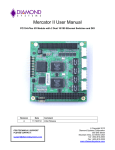
Declaration of Conformity
DUAL DISPLAY DIGITAL
MULTIMETER
MODEL: GDM-8245
User Manual
We
GOOD WILL INSTRUMENT CO., LTD.
No. 7-1, Jhongsing Rd, Tucheng City, Taipei County 236. Taiwan
GOOD WILL INSTRUMENT (SUZHOU) CO., LTD.
No.69 Lushan Road, Suzhou New District Jiangsu, China.
declares that the below mentioned product
GDM-8245
is herewith confirmed to comply with the requirements set out in the Council Directive
on the Approximation of the Law of Member States relating to Electromagnetic
Compatibility (89/336/EEC, 92/31/EEC, 93/68/EEC) and Low Voltage Equipment
Directive (73/23/EEC, 93/68/EEC).
For the evaluation regarding the Electromagnetic Compatibility and Low Voltage
Equipment Directive, the following standards were applied:
◎ EMC
EN 61326-1: Electrical equipment for measurement, control and laboratory use ––
EMC requirements (1997+A1: 1998)
Conducted and Radiated Emissions
Electrostatic Discharge
EN55011 Group II class B: 1998
EN 61000-4-2: 1995
Current Harmonic
Radiated Immunity
EN 61000-3-2: 1995
EN 61000-4-3: 1996
Voltage Fluctuation
Electrical Fast Transients
EN 61000-3-3: 1995
EN 61000-4-4: 1995
Surge Immunity
------------------------EN 61000-4-5: 1995
Conducted Susceptibility
------------------------EN 61000-4-6: 1996
Voltage Dips/ Interrupts
------------------------EN 61000-4-11: 1994
◎ Safety
Good Will Instrument Co., Ltd.
GW Part No. 82DM-82450MI
Low Voltage Equipment Directive 73/23/EEC & amended by 93/68/EEC
IEC/EN 61010-1: 2001
DUAL DISPLAY DIGITAL MULTIMETER
USER MANUAL
TABLE OF CONTENTS
DUAL DISPLAY DIGITAL MULTIMETER
USER MANUAL
PAGE
1.
SAFETY SUMMARY………………………………………………
1
2.
INTRODUCTION…………………………………………………..
5
3.
SPECIFICATION…………………………………………………..
6
4.
OPERATION INSTRUCTION……………………………………. 11
5.
MEASUREMENT TUTORIAL…...………………………………. 14
6.
MEASUREMENT TECHNIQUES......…………………………… 18
7.
MAINTENANCE…………………………………………………... 22
1.SAFETY SUMMARY
Please take a moment to review these safety terms and symbols
which may appear in this manual or on Equipment to prevent
damage to the instrument.
WARNING. Warning statements identify condition or
practices that could result in injury or loss of life.
CAUTION. Caution statements identify conditions or
practices that could result in damage to this product or
other property.
Measurement category I is for measurements performed on circuits not
directly connected to MAINS.
Measurement category II is for measurements performed on circuits
directly connected to the low voltage installation.
Measurement category III is for measurements performed in the building
installation.
Measurement category IV is for measurements performed at the source of
the low-voltage installation.
3
1
DUAL DISPLAY DIGITAL MULTIMETER
USER MANUAL
DUAL DISPLAY DIGITAL MULTIMETER
USER MANUAL
FOR UNITED KINGDOM ONLY
DANGER High Voltage
NOTE: This lead/appliance must only be wired by
competent persons
ATTENTION refer to Manual
WARNING: THIS APPLIANCE MUST BE EARTHED
IMPORTANT: The wires in this lead are coloured in
accordance with the following code:
Protective Conductor Terminal
Green/ Yellow: Earth
Blue:
Neutral
Brown:
Live(Phase)
(ground) Earth Terminal
Frame or Chassis Terminal
As the colours of the wires in main leads may not correspond
with the colours marking identified in your plug/appliance,
proceed as follows:
The wire which is coloured Green & Yellow must be
connected to the Earth terminal marked with the letter E or by
the earth symbol
or coloured Green or Green & Yellow.
The wire which is coloured Blue must be connected to the
2
3
DUAL DISPLAY DIGITAL MULTIMETER
USER MANUAL
DUAL DISPLAY DIGITAL MULTIMETER
USER MANUAL
terminal which is marked with the letter N or coloured Blue or
Black.
2. INTRODUCTION
The wire which is coloured Brown must be connected to the
terminal marked with the letter L or P or coloured Brown or
Red.
If in doubt, consult the instructions provided with the
equipment or contact the supplier.
This cable/appliance should be protected by a suitably rated
and approved HBC mains fuse : refer to the rating
information on the equipment and/or user instructions for
details. As a guide, cable of 0.75mm² should be protected by
a 3A or 5A fuse. Larger conductors would normally require
13A types, depending on the connection method used.
Any moulded mains connector that requires removal
/replacement must be destroyed by removal of any fuse &
fuse carrier and disposed of immediately, as a plug with
bared wires is hazardous if a engaged in live socket. Any rewiring must be carried out in accordance with the information
detailed on this label.
4
This instrument is a portable, bench-type dual display digital
multimeter with a good-performance 50000 counts designed for general
purpose application. The dual display allows you to display two functions
of the input signal being measured.
Features
z 50000 counts DMM
z Multi-function ACV, DCV, ACA, DCA, R, C , Hz, Continuity Beeper,
Diode Test, MAX/MIN, REL, HOLD, dBm
z Dual display Indicate ACV and Hz or DCV (ACV) and dBm
z Manual or Autoranging
z 0.03% DCV accuracy
z 20A high current range
z 1000V high voltage range
z AC True RMS or AC+DC True RMS.
5
DUAL DISPLAY DIGITAL MULTIMETER
USER MANUAL
DUAL DISPLAY DIGITAL MULTIMETER
USER MANUAL
3.SPECIFICATIONS
RANGE
500mV
5V
50V
500V
1000V
The specifications are operated under the essential conditions as follows:
z A 1-year calibration cycle.
z An operating temperature of 18 to 28℃ (64.4 to 82.4℉)
z Relative humidity not exceeding 75%
z Accuracy is expressed as ±(percentage of reading + digits).
z The AC specification is based on the 50% of duty cycle.
1. DC VOLTAGE
RANGE
500mV
5V
50V
500V
1000V
RESOLUTION
10μV
100μV
1mV
10mV
100mV
ACCURACY
0.03%+4
0.03%+9
INPUT IMPEDANCE
10MΩ
11.1 MΩ
10.1MΩ
10MΩ
10MΩ
Input Impedance
Normal Mode Rejection Ratio
Common Mode Rejection Ratio
Common Mode Voltage (Max.)
Approx. 10MΩ in parallel with <100pF, all ranges.
>60dB at 60Hz or 50Hz.
>90dB at 60Hz or 50Hz.
500V dc or peak ac.
450V
dc or peak ac continuous on 500mV range.
Maximum Input
1000V dc or peak ac continuous on other range.
63.80 dBm ~-97.7 dBm
dBm (ref 600Ω)
When the input exceeds the full scale of the selected range, the display will appear
“—OL—“ of over-range indication.
2. TRUE RMS AC OR AC+DC VOLTAGE
Accuracy
between 2% of range and full range.
RANGE
500mV
5V
50V
500V
1000V
20Hz45Hz
1%+15
1%+15
1%+15
1%+15
1%+15
45Hz1kHz1kHz
2kHz
0.5%+15
0.5%+15
0.5%+15
0.5%+15
0.5%+15
6
2kHz10kHz
1%+15
1%+15
1%+15
10kHz20kHz
2%+30
2%+30
2%+30
—————————
—————————
20kHz50kHz
5%+30
5%+30
5%+30
RESOLUTION
10μV
100μV
1mV
10mV
100mV
INPUT IMPEDANCE
10MΩ
11.1 MΩ
10.1MΩ
10MΩ
10MΩ
Input Impedance
Approx. 10MΩ in parallel with < 100pF,all ranges.
Maximum Input
450V dc or peak ac continuous on 500mV range.
1000V rms on other range.
63.8dBm ~ -97.7dBm
dBm ( ref 600Ω)
Crest Factor Range 3.0 at full scale.
When the input exceeds the full scale of the selected range, the display will appear
“—OL—“ of over-range indication.
3. FREQUENCY MEASUREMENT AT ACV RANGE
RANGE
FREQUENCY INPUT LEVEL (SINE WAVE)
500mV
10Hz ~ 50kHz
≧ 120mV
ACCURACY
0.05%+1
50k ~ 150kHz
≧ 200mV
0.05%+1
5V
10Hz ~ 200kHz
≧ 1.2V
0.05%+1
50V
20Hz ~ 200kHz
≧ 1.2V
0.05%+1
500V
20Hz ~ 1kHz
≧ 12V
0.05%+1
AC+DC measurement does not support AC+Hz function.
Maximum Input
450V peak ac continuous on 500mV range.
500V peak ac continuous on the other range.
4. DC Current
RANGE
500μA
5mA
50mA
500mA
2A
20A
RESOLUTION
0.01μA
0.1μA
1μA
10μA
100μA
1mA
ACCURACY
0.2%+2
0.2%+2
0.2%+2
0.2%+2
0.3%+2
0.3%+2
7
BURDEN VOLTAGE
0.7Vmax.
0.7Vmax.
0.7Vmax.
0.8Vmax.
0.8Vmax.
0.9Vmax.
DUAL DISPLAY DIGITAL MULTIMETER
USER MANUAL
DUAL DISPLAY DIGITAL MULTIMETER
USER MANUAL
500μA,5mA,50mA,500mA,2A 5 ranges fuse protection.
20A range no fuse,15 seconds max.
When the input exceeds the full scale of the selected range, the display will appear
“—OL—“ of over-range indication.
5. TRUE RMS AC OR AC+DC CURRENT
Accuracy
Between 2% of range and full range.
RANGE
20Hz-45Hz
45Hz-2kHz
2kHz-10kHz
10kHz-20kHz
Protection
500μA
1%+15
0.5%+15
1%+15
2%+15
5mA
1%+15
0.5%+15
1%+15
2%+15
50mA
1%+15
0.5%+15
1%+15
2%+15
500mA
1%+15
0.5%+15
2A
1%+15
0.5%+15
—————————
20A
1%+15
0.5%+15
—————————
Protection
—————————
500μA,5mA,50mA,500mA,2A 5 ranges fuse protection.
20A range no fuse,15 seconds max.
Crest Factor Range 3.0 at full scale.
The burden voltage is the same as the DC current.
When the input exceeds the full scale of the selected range, the display will appear
“—OL—” of over-range indication.
6. FREQUENCY MEASUREMENT AT ACA RANGE
RANGE FREQUENCY INPUT LEVEL (SINE WAVE)
500μA 10Hz ~ 20kHz
≧ 90μA
ACCURACY
5mA
10Hz ~ 20kHz
≧ 0.9mA
0.05%+1
0.05%+1
50mA
10Hz ~ 20kHz
≧ 9mA
0.05%+1
500mA 10Hz ~ 20kHz
≧ 90mA
0.05%+1
2A
10Hz ~ 2kHz
≧ 1A
0.05%+1
20A
10Hz ~ 2kHz
≧ 9A
0.05%+1
AC+DC measurement does not support AC+Hz function.
8
7.RESISTANCE
RANGE
500Ω
5kΩ
50kΩ
500kΩ
5MΩ
20MΩ
Open-circuit Voltage
Protection
8. CAPACITANCE
RESOLUTION
0.01Ω
0.1Ω
1Ω
10Ω
100Ω
1kΩ
ACCURACY
0.1%+4
0.1%+2
0.1%+2
0.1%+2
0.2%+2
0.3%+2
3.2 volts maximum on 500Ω, 1.3 volts maximum on all other
ranges.
450V dc or peak ac continuous.
RANGE:
5n *
RESOLUTION
0.001n
ACCURACY
≧1nF: 2%+10
<1nF & ≧0.5nF: 2%+20
50n
0.01n
≧10nF: 2%+10
<10nF & ≧5nF: 2%+30
500n
5μ
50μ
0.1n
1n
10n
2%+4
2%+4
2%+4
*5n range tends to be interfered by the test lead’s impedance and position. For the
accuracy, please measure the range on the input terminal directly.
Protection
450V dc or peak ac continuous.
9. DIODE CHECK
Description
Open Voltage
Maximum Forward
Voltage
Protection
Display read forward voltage of diode.
3.1V approx.
1.5V
450V dc or peak ac continuous.
9
DUAL DISPLAY DIGITAL MULTIMETER
USER MANUAL
DUAL DISPLAY DIGITAL MULTIMETER
USER MANUAL
4. OPERATION INSTRUCTIONS
10. CONTINUITY BEEPER
Description
Built in buzzer sounds if conductance is less than 5 ohm.
Open Voltage
3 volts maximum.
Protection
450V dc or peak ac continuous.
11. ENVIRONMENTAL
Indoor use, altitude up to 2000m.
Ambient Temperature 0℃ to 50℃.
Operation
Relative
Humidity 75% (Maximum).
Environment
Installation category II
Pollution Degree
2
-40℃ to 70℃.
Storage temperature
Up to 75%, 0℃ to 35℃, Up to 50%, 35℃ to 50℃, except
the ranges of 2MΩ and 20MΩ which are up to 75% , 0℃
Relative Humidity
to 35℃.
12. GENERAL
Maximum Common 500V dc or peak ac ( low terminal potential with
Mode Voltage
respect to power line ground ).
Warm Up
Power source
Accessories
Dimension
Weigh
0.5 hours to achieve rated accuracy.
AC 100V/120V/230V±15%, 50/60Hz, 8.0VA, 6.0W.
Test Lead
×1
Instruction manual × 1
251(W)×91(H)×291(D) m/m
Approx. 2.6 kg
4-1 Front panel and rear panel
The front panel, shown in Figure4-1, contains three main elements:
the input terminals, the primary and secondary displays, and the push
buttons.
The rear panel, shown in Figure 4-2, contains the AC power-line
connector, and fuse & line voltage selector, and input fuse holder.
4-2 The [SHIFT] key and function keys
[SHIFT] button is used to enable the secondary function of certain
function keys that with blue symbols printed above. The SHIFT LED
will be on after pressed the [SHIFT] button. At this time, only the
buttons with blue symbols are workable. To release SHIFT function,
press [SHIFT] again. For example, to select DCmV function, press
[SHIFT], then press [DCV] ([DCmV]).
4-3 Warm up
The instrument requires half-an-hour warm up to achieve rated
accuracy.
4-4 Over-range indication
An input is over-range if it exceeds the full scale of the selected range.
GDM-8245 indicates an input is over-range by lighting the “—OL—”
pattern on display.
WARNING:To avoid electrical shock, the power cord
protective grounding conductor must be connected to
ground.
4-5 No specification indication
On AC+Hz measured mode, when an input is less sensitivity, the
secondary display show “————”. When the frequency of an input
exceeds 51kHz, the primary display will show “————”.
CAUTION:To avoid damaging the instrument, do not use
it in a place where ambient temperature exceeds 50℃.
10
11
DUAL DISPLAY DIGITAL MULTIMETER
USER MANUAL
DUAL DISPLAY DIGITAL MULTIMETER
USER MANUAL
z Figure 4-1 Front Panel
4-6 Input overload protection
The maximum allowable input is shown as table 4-1. Please proceed
the measurement accordingly.
Table 4-1:
FUNCTION
DCV
ACV (AC+DC)
RANGE
5V~1000V
5V~1000V
DCA,ACA(AC+DC)
DC,AC20A(AC+DC)
DC,ACmV (AC+DC)
OHM
CAPACITANCE
500μA~2A
20A
500mV
all ranges
all ranges
MAXIMUN INPUT
1000Vdc or peak ac
1000V rms continuous &
107 V•Hz maximum
fuse protected: 2A 250V
no fuse protected
450V dc or ac peak
450V dc or ac peak
450V dc or ac peak
WARNING: To avoid shock hazard and/or instrument damage,
do not apply input potentials that exceed the input overload
limits shown in table 4-1.
4-7 Input connections to common
WARNING: To avoid shock hazard and/or instrument damage,
do not connect the common input terminal to any source of
more than 500 volts DC or peak AC above earth ground.
z Figure 4-2 Rear Panel
12
13
DUAL DISPLAY DIGITAL MULTIMETER
USER MANUAL
DUAL DISPLAY DIGITAL MULTIMETER
USER MANUAL
5. MEASUREMENT TUTORIAL
5-3. Resistance, capacitance, continuity beeper measurements
1).Press the button to select function.
2).Press [▲]or[▼]to the desired range. Press [AUTO/MAN] button to
5-1. Voltage measurements (DCV, ACV, DCmV, ACmV)
1).Press the button to select desired function.
2).Press [▲]or[▼]to the desired range (if you have no idea about the
value of input, we suggest you always start at the highest range).
Press [AUTO/MAN] button for manual or auto-ranging selection.
3).Connect the test lead to the V and COM input terminals of the
instrument.
4).Connect the test lead to the measuring points and read the displayed
value.
NOTE: After measuring high voltage to 1000V dc, errors may
occur when the 100μV is measured. Allow up to one minute
prior to making low-level measurements
change manual or auto-ranging.
3).Connect the test lead to the Ω,
and COM input terminals of
the instrument.
4).Connect the test lead to the measuring points and read the displayed
value.
5-4. Diode test measurements
1).Press the button to select function.
2).Connect the test lead to the
and COM input terminals of the
instrument.
3).Connect the test lead to the semiconductor junction (diode or
transistor) as shown in Figure 5-1,and read the displayed value.
z Figure 5-1
5-2. Current measurements (DCA, DC 20A, ACA, AC 20A)
1).Press the button to select function.
2).Press [▲]or[▼]to the desired range.(if you have no idea about the
value of input. we suggest you always start at the highest
range).Press [AUTO/MAN] button to change manual or autoranging.
3).Connect the test lead to the 2A or 20A and COM input terminals of
the instrument.
4).Connect the test lead to the measuring points and read the displayed
value.
14
Connect to
Connect to
“
”
terminal.
“COM”
terminal
5-5. dBm measurements
This function converts a voltage measurement into dBm. The function
can be selected only when a voltage function (volts ac, volts dc, or
volts ac+dc) is selected. Press [dBm] button, the secondary display
shows the dBm value that reposed on the voltage value showed in the
primary display.
15
DUAL DISPLAY DIGITAL MULTIMETER
USER MANUAL
For example, if [dBm] is pressed when measuring voltage in the max
mode, the maximum value is converted to dBm. To release the dBm
function, press [dBm] again. The dBm mode and AC+Hz mode are
not selected concurrently.
The standard reference impedance of the instrument is 600Ω.
5-6. AC+Hz measurements
The function can be selected only when ac range is selected. Press
[SHIFT], then press [AC+Hz], the secondary display shows the
frequency of the input signal that is higher than the sensitivity. The
frequency measurement does not depend on the max/min, rel, or hold
mode. In this mode, the reading rate of the DMM may be slower than
the normal state.
To release the AC+Hz function, press [AC+Hz] again. The dBm mode
and AC+Hz mode are not selected concurrently.
5-7 AC+DC measurements
The function can be selected only when voltage or current function is
selected. Press [AC+DC] button, the primary display shows the true
rms value of the input signal including the ac component and dc
component. In this mode, the reading rate of the DMM is slower than
the normal state.
To release the AC+DC function, press other function (voltage ac or
dc, current ac or dc, R,C, Continuity Beeper, Diode Test) key.
16
DUAL DISPLAY DIGITAL MULTIMETER
USER MANUAL
5-8 MAX/MIN measurements
The MAX/MIN mode causes the DMM to hold the lowest and highest
readings. Press [MAX/MIN] button to the MAX mode. The highest
will be displayed in continuous input. In the MAX mode, press
[MAX/MIN] button to the MIN mode. The lowest will be displayed in
continuous input. In the MIN mode, press [MAX/MIN] button to
release the MAX/MIN mode.
5-9. REL measurements
When the [REL] button is pressed, the meter stores the present reading
and displays subsequent measurements as the difference between the
measured value and the stored reading.
In the MAX/MIN mode, set [REL] button to the REL mode. The
maximum or minimum reading will become the relative base.
5-10. HOLD measurements
The HOLD mode that allows you to keep your eyes fixing on the
probes when taking measurements in difficult or hazardous
circumstances, then read the display when it is convenient and safe.
Press the [HOLD] button the last reading is held on the display in all
function. To release the HOLD function, press [HOLD] again.
17
DUAL DISPLAY DIGITAL MULTIMETER
USER MANUAL
DUAL DISPLAY DIGITAL MULTIMETER
USER MANUAL
6.MEASUREMENT TECHNIQUES
z Figure 6-1: Voltage Conversion
6-1 dBm measurement technique
dBm is defined as above or below a 1mW reference. A voltage
measurement is converted to dBm using the following formula:
dBm=10*log 10 (1000*voltage value2/reference impedance.)
The standard reference impedance of the instrument is 600Ω.
For example, 0.7746V will be convert to 0 dBm.
6-2 True rms measurement
The true rms (root-mean-square) value of a waveform is equivalent
to dc value that causes the same amount of heat to be dissipated in a
resistor.
Since average-responding meters have been in use for so long, you
may have accumulated test or reference data based on them. Figure 61 illustrates the relationship between ac and dc components for
common waveforms, and compares readings for true rms meters and
average-responding meters. Figure 6-1 will help you convert between
the two measurement methods.
18
19
DUAL DISPLAY DIGITAL MULTIMETER
USER MANUAL
DUAL DISPLAY DIGITAL MULTIMETER
USER MANUAL
z Figure 6-2: Crest Factor
6-3 AC+DC measurement
A signal includes an ac component and a dc level. The relationship
between the total rms value of the signal and the ac component and the
dc component is:
rms total= ( ac component rms) 2 + (dc component) 2
6-4 Crest factor
Crest factor is often overlooked in determining the accuracy of an ac
measurement. Crest factor is defined as the ratio of the peak signal
amplitude to the rms value of the signal.
If an input signal has a crest factor of 3.0 or less, voltage
measurements will not be in error due to dynamic range limitations at
full-scale.
The waveforms in Figure 6-2 show signals with increasing value of
crest factor. As you can see from the series of waveforms, a signal with
a crest factor above 3.0 is unusual.
20
21
DUAL DISPLAY DIGITAL MULTIMETER
USER MANUAL
DUAL DISPLAY DIGITAL MULTIMETER
USER MANUAL
7.MAINTENANCE
7-3 Line voltage conversion
The primary winding of the power transformer is tapped to permit
operation from 100/120V, or 230V AC 50/60Hz line voltage.
Conversion from one line voltage to another is done by changing the
line voltage selector switch as shown in Figure 4-2. The rear panel
identifies the line voltage to which the unit was factory set. To convert
to a different line voltage, perform the following procedure:
1). Make sure the power cord is unplugged.
2). Adjust the line voltage selector switch to the desired line voltage
position.
3). A change in line voltage may also require a corresponding change
of fuse value. Install the correct fuse value as listed on rear panel.
The following instructions are executed by qualified personnel only. To
avoid electrical shock, do not perform any servicing other than the
operating instructions unless you are qualified to do so.
7-1 Line fuse replacement
If the fuse blows, the DMM would not work. Try to determine and
correct the cause of the blown fuse, then replace the fuse with correct
rating and type shown as below:
FUSE RATING AND TYPE
100/120V
T0.1A 250V
230V
T0.08A 250V
F101 on PCB
T0.5A 250V
7-2 Current fuse replacement
The current fuse protects the 500μA~ 2A range from an input current
7-4 Cleaning
To keep the instrument clean, wipe the case with a damp cloth and
detergent. Do not use abrasives or solvents.
greater 2A.To replace the current fuse, perform the following steps:
1).Turn off the power, disconnect the power line and remove the test
leads.
2).Place the end of a flat blade screwdriver into the slot of the fuse
holder on the front panel. Push and carefully rotate the fuse carrier
turn counterclockwise till remove the fuse and the fuse carrier off
the front panel.
3).Remove the defective fuse and replace the correct fuse (F2A 250V).
22
23