1
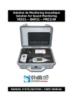
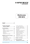
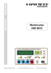
Distortion Meter
HM8027
Service-Manual
General information regarding the CE marking
General information regarding the CE marking
KONFORMITÄTSERKLÄRUNG
DECLARATION OF CONFORMITY
DECLARATION DE CONFORMITE
DECLARACIÓN DE CONFORMIDAD
Hersteller / Manufacturer / Fabricant / Fabricante:
HAMEG Instruments GmbH · Industriestraße 6 · D-63533 Mainhausen
Die HAMEG Instruments GmbH bescheinigt die Konformität für das Produkt
The HAMEG Instruments GmbH herewith declares conformity of the product
HAMEG Instruments GmbH déclare la conformite du produit
HAMEG Instruments GmbH certifica la conformidad para el producto
Bezeichnung:
Product name:
Designation:
Descripción:
Klirrfaktor Messbrücke
Distortion Meter
Distorsiomètre
Medidor de distorsión
Typ / Type / Type / Tipo:
HM8027
mit / with / avec / con:
HM8001-2
Optionen / Options /
Options / Opciónes:
–
mit den folgenden Bestimmungen / with applicable regulations /
avec les directives suivantes / con las siguientes directivas:
EMV Richtlinie 89/336/EWG ergänzt durch 91/263/EWG, 92/31/EWG
EMC Directive 89/336/EEC amended by 91/263/EWG, 92/31/EEC
Directive EMC 89/336/CEE amendée par 91/263/EWG, 92/31/CEE
Directiva EMC 89/336/CEE enmendada por 91/263/CEE, 92/31/CEE
Niederspannungsrichtlinie 73/23/EWG ergänzt durch 93/68/EWG
Low-Voltage Equipment Directive 73/23/EEC amended by 93/68/EEC
Directive des equipements basse tension 73/23/CEE amendée par 93/68/CEE
Directiva de equipos de baja tensión 73/23/CEE enmendada por 93/68/EWG
Angewendete harmonisierte Normen / Harmonized standards applied /
Normes harmonisées utilisées / Normas armonizadas utilizadas:
HAMEG instruments fulfill the regulations of the EMC directive. The
conformity test made by HAMEG is based on the actual generic- and
product standards. In cases where different limit values are applicable,
HAMEG applies the severer standard. For emission the limits for
residential, commercial and light industry are applied. Regarding the
immunity (susceptibility) the limits for industrial environment have
been used.
The measuring- and data lines of the instrument have much influence
on emmission and immunity and therefore on meeting the acceptance
limits. For different applications the lines and/or cables used may
be different. For measurement operation the following hints and
conditions regarding emission and immunity should be observed:
1. Data cables
For the connection between instruments resp. their interfaces and
external devices, (computer, printer etc.) sufficiently screened cables
must be used. Without a special instruction in the manual for a reduced
cable length, the maximum cable length of a dataline must be less than
3 meters and not be used outside buildings. If an interface has several
connectors only one connector must have a connection to a cable.
Basically interconnections must have a double screening. For IEEE-bus
purposes the double screened cables HZ72S and HZ72L from HAMEG
are suitable.
2. Signal cables
Basically test leads for signal interconnection between test point and
instrument should be as short as possible. Without instruction in the
manual for a shorter length, signal lines must be less than 3 meters
and not be used outside buildings.
Signal lines must screened (coaxial cable - RG58/U). A proper ground
connection is required. In combination with signal generators double
screened cables (RG223/U, RG214/U) must be used.
Verschmutzungsgrad / Degree of pollution / Degré de pollution / Nivel de
polución: 2
3. Influence on measuring instruments.
Under the presence of strong high frequency electric or magnetic fields,
even with careful setup of the measuring equipment an influence of
such signals is unavoidable.
This will not cause damage or put the instrument out of operation. Small
deviations of the measuring value (reading) exceeding the instruments
specifications may result from such conditions in individual cases.
Elektromagnetische Verträglichkeit / Electromagnetic compatibility /
Compatibilité électromagnétique / Compatibilidad electromagnética:
HAMEG Instruments GmbH
Sicherheit / Safety / Sécurité / Seguridad:
EN 61010-1: 1993 / IEC (CEI) 1010-1: 1990 A 1: 1992 / VDE 0411: 1994
Überspannungskategorie / Overvoltage category / Catégorie de surtension /
Categoría de sobretensión: II
EN 61326-1/A1: Störaussendung / Radiation / Emission: Tabelle / table /
tableau 4; Klasse / Class / Classe / classe B.
Störfestigkeit / Immunity / Imunitee / inmunidad:
Tabelle / table / tableau / tabla A1.
EN 61000-3-2/A14: Oberschwingungsströme / Harmonic current emissions
/ Émissions de courant harmonique / emisión de corrientes armónicas:
Klasse / Class / Classe / clase D.
EN 61000-3-3: Spannungsschwankungen u. Flicker / Voltage fluctuations
and flicker / Fluctuations de tension et du flicker / fluctuaciones de tensión
y flicker.
Datum / Date / Date / Fecha
22.07.2004
Unterschrift / Signature / Signatur / Signatura
G. Hübenett
Product Manager
2
Subject to change without notice
Content
Declaration of Conformity
2
General information regarding the CE-marking
2
Distortion meter HM8027
4
Specifications
5
Control elements
6
Operational check
6
Ajustment
7
Circuit and layout diagrams
8
Subject to change without notice
3
HM8027
Distortion Meter
HM8027
Frequency range 20 Hz to 20 kHz
Mainframe HM8001-2
Resolution up to 0.01 %
Low inherent distortion of 0.005 %
Automatic frequency fine tuning (capture range 15 %)
Control output for residual distortion measurement
HZ32 Test cable
A complete measurement system for AF measurement
equipment in combination with the HM8037
Mainframe HM8001-2 required for operation
HM8037 Low-distortion
sine wave generator
4
Subject to change without notice
Specifications
Distortion Meter HM8027
Valid at 23 °C after a 30 minute warm-up period
Monitor output
Output voltage:
Output impedance:
1 mV/digit (short-circuit proof)
10 kΩ
Input attenuation
1 constant attenuator – 20 dB
1 constant attenuator – 10 dB
1 variable attenuator – 15 dB
Frequency range
20 Hz - 20 kHz
subdivided into 3 ranges
variable frequency control 10:1, overlapping
ranges
Distortion measurement range
0.01 % - 50 %, subdivided into 2 ranges
Full range:
10 % and 100 %
Display resolution:
100 % range: 0.1 %
10 % range: 0.01 %
Display accuracy
100 % range:
10 % range:
±5 % ±1 digit for k ≤ 10 %
±5 % ±1 digit for k ≤ 1 %
Miscellaneous
1 selectable high-pass filter: 1 kHz, 12 dB/octave
Power supply
+12 V/60 mA
(from mainframe):
- 12 V/60 mA
+5 V/100 mA
(∑ = 1.94 W)
Operating temperature:
+10° C to +40° C
Max. relative humidity:
80 % (without condensation)
Dimensions (W x H x D) (without 22-pole flat plug):
135 x 68 x 228 mm
Weight:
approx. 0.65 kg
Inherent distortion + noise
≤ 0.5 digit
Fundamental rejection
30 dB greater than the measured distortion factor
or ≥ 70 dB in the 100 % range
or ≥ 90 dB in the 10 % range
Input voltage
min. for 100 % calibration: 300 mV
max. for 100 % calibration:50 V
Input impedance
100 kΩ
Accessories supplied: Operator’s Manual
Optional accessories: HZ33/HZ34 BNC Test Cable, HZ20 BNC banana adapter,
HZ10 Silicone test leads
w w w. h a m e g . co m
HM8014E/140705/ce · Subject to alterations · © HAMEG Instruments GmbH · ® Registered Trademark · DQS-certified in accordance with DIN EN ISO 9001:2000, Reg.-No.: DE-071040 QM
HAMEG Instruments GmbH · Industriestr. 6 · D-63533 Mainhausen · Tel +49 (0) 6182 800 0 · Fax +49 (0) 6182 800 100 · www.hameg.com · [email protected]
A Rohde & Schwarz Company
Subject to change without notice
5
Control elements
Control elements
Display(7-segment LEDs)
3-digit display for indication of the measured distortion
factor in %.
FREQUENCY RANGE
(Pushbutton switches)
Selection of frequency range for signal under test (20 Hz200 Hz, 200 Hz-2 kHz, 2 kHz-20 kHz).
1kHz HIGH-PASS
(Pushbutton switch)
1 kHz high-pass filter with a roll off of 12 dB/octave for rejection of low frequency hum and noise.
ATTENUATOR (Pushbutton switch)
Input signal attenuation with two pushbutton switches of
20 dB or 10 dB attenuation, respectively. They can be used
separately. Both pushbutton switches activated, together
with the variable attenuator must enable a 100% reading
when in the calibration mode, otherwise the input voltage
should be adjusted.
OUTPUT (BNC connector)
Monitor output for distortion factor (Residual distortion).
Output voltage is 1 mV/digit.
TUNING INDICATOR (LEDs)
If the built-in filter is incorrectly tuned, one of the two LEDs
will indicate in which direction the filter frequency deviates
from the input frequency. Turn the tuning knob in the opposite direction until the LED goes out.
TUNING (Adjusting knob)
Permits tuning of the built-in filter for maximum rejection
of the fundamental wave. Fine tuning is automatic with a
capture range of approx. 15%. If both LEDs are off, the
filter is properly synchronised.
DISTORTION (Pushbutton switches)
Range selection for 10% or 100% fuII scale.
100%-CALIBRATION
(Pushbutton switch)
Selection of calibration mode. Adjustment for 100% reading
with LEVEL .
LEVEL (Adjusting knob)
Continuous attenuation of input signal up to max. 15 dB to
achieve 100% reading when in the calibration mode.
INPUT (BNC connector)
Input for measurement signal. The permissible input voltage range is 0.3 V - 50 V for a valid measurement.
6
Subject to change without notice
Operational check
Measuring equipment required
– 2 Low Distortion Generators (e.g. HM8037)
– Digital multimeter with 200 mVAC range (e.g. HM8012)
Check of input sensitivity
Setting:
2k
Cal.
max.
0dB released
1) Adjust the output voltage of the HM8037 to 300 mV at
1 kHz.
2) Connect the output of the HM8037 to the input
of
HM8027.
3) With the above setting the display of the HM8027 should
indicate a value ≥100.
Check of input signal attenuation
Setting:
2k
Cal.
max.
odB released
of the
1) Connect the output of the HM8037 to the input
HM8027.
2) Adjust readout to 100 by means of the amplitude control
of the Sine Wave Generator HM8037.
Adjustment
Control range of automatic frequency tuning
Setting:
2k
Cal.
100%
Cal. released
3) Check the following values:
Min. position, = 0 dB, Display ≤19
Max. position, = –10 dB, Display ≤30
Max. position, = –20 dB, Display ≤10
Check of monitor output
Setting:
2k
Cal.
max.
0dB released
of
1) Connect the output of the HM8037 to the input
HM8027.
2) Adjust the output voltage of the Sine Wave Generator
HM8037 at 1 kHz to get a readout of 100 on HM8027.
3) Measure the output voltage at the monitor output
of
HM8027 using the DMM HM8012. The obtained value should
be 100 mV ±5%.
Check of high pass filter
Setting:
2k
Cal.
100%
Check of residual distortion
1) Connect the output of the HM8037 to the input
of
HM8027.
2) Calibrate the readout of the HM8027 to 100.
3) Check the readout of the HM8027 for ≤0.01 on 10% range
according to the frequencies listed below.
Range
Frequencies to be checked
200 Hz
20 Hz 200 Hz
2 kHz
200 Hz 2 kHz
20 kHz
2 kHz 10 kHz
Check of distortion measurement ranges
1) Adjust both Sine Wave Generators HM8037 for an output
of 1 V. Verify with HM8012. Frequency setting 200 Hz and
1600 Hz is recommended.
2) Connect both generators to the input of the HM8027 according to the circuit below.
2k
tuned 100% 100%
Adjustment
Cal. released
1) Set the frequency of the Sine Wave Generator HM8037 to
100 Hz.
2) Calibrate the display of HM8027 to 100.
3) Select the 100%-distortion range with one of the pushbuttons .
4) Switch the high-pass filter on by pushing pushbutton .
5) Check display for ≤5.
3) Setting:
1) Connect the output of HM8037 to input of HM8027.
Set the frequency to 1 kHz.
2) Calibrate the HM8027 to 100% and align the frequency by
means of the control knob .
3) Adjust the frequency control of HM8027 by means of the
control knob so, that the right LED just lights.
4) Adjust the frequency of HM8037 until the left LED lights.
5) The frequency setting of HM8037 should now be approx.
1.15 kHz. This corresponds to the specified 15% automatic
tuning range.
Cal
released
4) Reading on HM8027 should be 10.0 ±5%.
5) Change the output voltage of Generator 2 to 100 mV (–20 dB).
Verify with HM8012.
6) Change the setting of the distortion measurement range to
10% by pushing .
7) Check readout of HM8027 for 1.00 ± 5%.
8) In this case it must be possible to measure a signal of 1.6 kHz
with an amplitude of 100 mV at output of HM8027.
Display zero adjustment
Setting:
2k
Cal.
Gain adjustment
Setting:
2k
Cal.
mid posit.
0dB
-10dB
1) Adjust both sine wave generators HM8037 to an output of 1 V.
Verify with HM8012. Frequency setting 200 Hz and 1600 Hz
is recommended.
2) Connect both generators to the input of HM8027 according to the circuit in the section operational check.
3) Connect the HM8012 (setting 2 VAC) to test point E on the
test connector CN101.
4) Adjust the measured value to 300 mV by means of the amplitude control (A).
5) Tune the frequency control until the LEDs extinguish.
6) Select the 100% measurement range with .
7) Adjust the readout for 10.0 by means of VR103.
Calibration adjustment
1) Same settings and connections as Gain adjustment.
2) Select the calibration mode by means of pushbutton
3) Adjust VR301 for 100% readout .
.
Adjustment of frequency control circuit
Setting:
2k
Cal.
-10dB
100%Cal.
1) Connect the output of HM8037 to the input of HM8027
(output voltage 1 V, 1 kHz).
2) Adjust the display
for 100 by means of the level control
knob .
3) Tune the frequency control until the LEDs extinguish.
4) Adjust the frequency control of HM8027 so that the right
LED lights.
5) Set the frequency of HM8037 to 1150 Hz.
6) Adjust VR101 so that the left LED lights.
Frequency compensation
1) Connect the output of HM8037 to the input of HM8027.
2) Tune the HM8027 for correct distortion reading.
3) Measure and take note of DC-voltage at the point A of the
test connector CN101 (-5 V DC typ.).
4) Adjust the frequency of HM8037 to 20 kHz.
5) Recalibrate and readjust the HM8027.
6) Adjust VC101 to obtain a DC-Voltage same as 3) ±100 mV.
Subject to change without notice
7
Circuit and layout diagrams
8
Subject to change without notice
Circuit and layout diagrams
Subject to change without notice
9
Circuit and layout diagrams
10
Subject to change without notice
Circuit and layout diagrams
Subject to change without notice
11
Oscilloscopes
Spectrum Analyzer
Power Supplies
Modular System
8000 Series
Programmable Instruments
8100 Series
4S-8027-00E0
authorized dealer
www.hameg.de
Subject to change without notice
4S-8027-00E0 / 09-11-2005-gw
© HAMEG Instruments GmbH
A Rohde & Schwarz Company
® registered trademark
DQS-Certification: DIN EN ISO 9001:2000
Reg.-Nr.: 071040 QM
HAMEG Instruments GmbH
Industriestraße 6
D-63533 Mainhausen
Tel +49 (0) 61 82 800-0
Fax +49 (0) 61 82 800-100
[email protected]