1
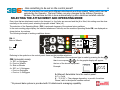
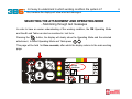
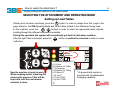
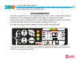
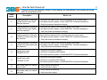
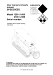
3B6 LOAD MOMENT INDICATOR (LMI) FOR MRT TELESCOPIC HANDLERS USER MANUAL SLIM-ST01 Su stabilizzatori 360° 0 1 2 3 4 5 6 7 8 9 10 11 12 13 14 15 16 17 18 19 20 21 22 23 24 25 26 27 28 29 0 0 1000 1001 4 4,5 5 5,5 6 6,5 7 7,5 8 8,5 9 9,5 10 10,5 11 11,5 12 12,5 13 13,5 14 14,5 15 15,5 1 5,7 110 2 6,7 100 3 7,9 100 4 9,1 100 5 10,3 100 6 11,5 100 7 12,8 100 8 14 100 9 15,2 100 10 16,6 100 5 5 4,5 4,2 4 5 5 4,5 4,2 4 4 3,2 3 2,8 5 5 4,5 4,2 4 4 3,2 3 2,8 2,4 2,4 2,1 2 4,5 4,5 4,5 4,2 4 4 3,2 3 2,8 2,4 2,4 2,1 2 1,65 4 4 4 3,7 3,5 3,2 3 2,8 2,8 2,4 2,4 2,1 2 1,65 1,6 1,4 1,35 1,2 1,15 3,2 3,2 3,2 3 3 2,8 2,8 2,4 2,2 2,2 2,2 2,1 2 1,65 1,6 1,4 1,35 1,2 1,15 1 0,95 3 3 3 3 2,8 2,8 2,4 2,2 2,2 2,1 1,9 1,9 1,8 1,65 1,6 1,4 1,35 1,2 1,15 1 0,95 0,85 0,8 0,8 2,8 2,8 2,8 2,8 2,8 2,55 2,4 2,2 2,1 2 1,9 1,8 1,65 1,6 1,5 1,4 1,35 1,2 1,15 1 0,95 0,85 0,8 0,8 2,8 2,8 2,8 2,8 2,65 2,5 2,3 2,15 2,05 1,9 1,8 1,7 1,6 1,5 1,45 1,4 1,35 1,2 1,15 1 0,95 0,85 0,8 0,8 2,4 2,4 2,4 2,4 2,3 2,3 2,2 2,1 1,95 1,8 1,7 1,6 1,55 1,45 1,45 1,4 1,35 1,2 1,15 1 0,95 0,85 0,8 0,8 11 29 Version 18/04/05 Complies to the MACHINES DIRECTIVE Standards: EN60204–1 , EN954, EN1207-2,EN 280 EMC according to the “Heavy Industrial Environment” category: EN50081-2, EN50082-2 2 INDEX What the load moment indicator does? LOAD MOMENT INDICATOR (LMI) FUNCTIONAL DESCRIPTION Which components are included in a LMI? SYSTEM LAY-OUT AND CONNECTIONS How is the LMI installed on the machine? COMPONENTS LOCATION ON THE MACHINE What’s the function of the control panel? CONTROL PANEL DESCRIPTION What happens when starting the machine? SWITCHING THE MACHINE ON What should be checked once the machine is running? SWITCHING THE MACHINE ON Is the control panel informing about safety on the machine? PANEL MONITORING– Lifting condition in % and alarms Is the control panel giving useful information to work? PANEL MONITORING– Main working data reading on the display Has something to be set on the control panel? SELECTING THE ATTACHMENT AND OPERATING MODE Is it easy to understand in which working condition the system is? SELECTING THE ATTACHMENT AND OPERATING MODE – Monitoring through text messages How to select the attachment ? SELECTING THE ATTACHMENT AND OPERATING MODE – Setting up load tables Can the LMI detect faults? AUTO DIAGNOSTIC How the fault shows up ? ALARM CODES AND ACTIONS TO TAKE AUTO DIAGNOSTIC – System internal working condition monitoring Geometric data and load data Hydraulic pressures data Angle and Extension data Status of digital input Sensors digital signals Status of digital Inputs from outside Status of digital Outputs to outside Angle and Extension read What should be known before operating with the machine? WARNINGS Page 3 4 5 6 7 8 9 10,11 12 13 14 15 16,21 22 23 24 25 26 27 28 29,30 31,32 What the load moment indicator does ? 3 The LMI aim is to ensure that the machine doesn’t exceed working condition limits, making the Operator aware and acting through alarms and shut-down of dangerous movements. LOAD MONITORING INDICATOR (LMI) FUNCTIONAL DESCRIPTION Working condition measurements Load Tables storage, comparing and processing Su stabilizzatori 360° PRESSURE TRANSDUCERS (Lifted load) 0 1 2 3 4 5 6 7 8 9 10 11 12 13 14 15 16 17 18 19 20 21 22 23 24 25 26 27 28 29 0 0 1000 1001 4 4,5 5 5,5 6 6,5 7 7,5 8 8,5 9 9,5 10 10,5 11 11,5 12 12,5 13 13,5 14 14,5 15 15,5 1 5,7 110 2 6,7 100 3 7,9 100 4 9,1 100 5 10,3 100 6 11,5 100 7 12,8 100 8 14 100 9 15,2 100 10 16,6 100 5 5 4,5 4,2 4 5 5 4,5 4,2 4 4 3,2 3 2,8 5 5 4,5 4,2 4 4 3,2 3 2,8 2,4 2,4 2,1 2 4,5 4,5 4,5 4,2 4 4 3,2 3 2,8 2,4 2,4 2,1 2 1,65 4 4 4 3,7 3,5 3,2 3 2,8 2,8 2,4 2,4 2,1 2 1,65 1,6 1,4 1,35 1,2 1,15 3,2 3,2 3,2 3 3 2,8 2,8 2,4 2,2 2,2 2,2 2,1 2 1,65 1,6 1,4 1,35 1,2 1,15 1 0,95 3 3 3 3 2,8 2,8 2,4 2,2 2,2 2,1 1,9 1,9 1,8 1,65 1,6 1,4 1,35 1,2 1,15 1 0,95 0,85 0,8 0,8 2,8 2,8 2,8 2,8 2,8 2,55 2,4 2,2 2,1 2 1,9 1,8 1,65 1,6 1,5 1,4 1,35 1,2 1,15 1 0,95 0,85 0,8 0,8 2,8 2,8 2,8 2,8 2,65 2,5 2,3 2,15 2,05 1,9 1,8 1,7 1,6 1,5 1,45 1,4 1,35 1,2 1,15 1 0,95 0,85 0,8 0,8 2,4 2,4 2,4 2,4 2,3 2,3 2,2 2,1 1,95 1,8 1,7 1,6 1,55 1,45 1,45 1,4 1,35 1,2 1,15 1 0,95 0,85 0,8 0,8 11 29 DUAL LENGTH AND ANGLE SENSOR * (Boom Geometric data ) AUTOMATIC SELECTIONS from micro-switches : - Outriggers - Turret rotation - Basket Data display and setting CONTROL PANEL l h Esc ACT r a Enter h l a OM READINGS : - % Tilting - Lifted load - Maximum load - Working radius (outreach) - Boom length - Boom angle - Operating mode -Attachment used - Diagnostic Alarms: Green/Amber/Red lights Automatic functions External alarm and automatic shut-down MANUAL SELECTIONS: - Forks - Winch - Basket - Jib *Remark: System complies to EN280 A1 CE standard therefore cable reel includes double angle and length sensors. Which components are included in a LMI? 4 It’s a system including sensors able to detect lifted load,boom position, a main unit and a control panel situated inside the cabin. SYSTEM LAY-OUT AND CONNECTIONS 1 L = 0,4m J5 J4 2 4 L=5,6m L =4,3m L =0,6m X3 L=0,25m X1 X2 X1A M X2A CONN. M12 L = 0,2m F L =6,6m 3 PRESSURE TRANSDUCERS Y11 4745-350 L =1m L =1m 6 L =1,5m L =1,5m 5 1 2 3 4 5 6 Main Unit Cable-Reel Cable-Reel Cable Main cable Pressure Transducers Cable Pressure Transducers (4) How is the LMI installed on the machine? 5 The sensors are positioned on the boom and cylinders in order to detect data when working, while the main unit and the control panel are located inside the cabin. Dual Length/Angle sensor: On the left side of the boom Main Unit with display in the cabin Nr.4 Pressure Transducers: on Main and Compensation cylinders What’s the function of the control panel? 6 It gives to the operator all information in order to work in safe conditions and allows proper setting . CONTROL PANEL DESCRIPTION Operating Mode Identification Symbols ( External automatic selections) Attachment Identification symbols (Manually selected from the control panel) Green/Amber/Red Lights showing working conditions ( Safety/ Alarm/Shut down) 1 2 3 4 l 5,5 A A Enter h Mod.3B6 -9.9 3.0 ACT 5 4 Set-up keys Graphic display for showing working data a l r Icon representing the machine and letters related to geometric data. 5,5 3A 1 2 3 4 5 OM h -6,8 r 99 a A Symbols and letters related to the display indications What happens when starting the machine? 7 The system is activated and automatically proceeds to its self test mode giving information to the Operator. SWITCHING THE MACHINE ON Starting the machine, the system automatically switches on and, for a few seconds, the machine model and the software version is shown ( dd.mm.yy= software date of development) 1 2 3 4 l A A h STS2_2 dd-mm-yy MRT1635R ACT r a Enter h 5 Mod.3B6 a l r 1 2 3 4 5 OM A Afterwards, still for few seconds, it shows the machine working condition, that is the load table (attachment selected ) and the present Operating Mode. 1 2 3 4 l A A h Forks Confirm r a Enter h 5 Mod.3B6 a r l A What should be checked once the machine is running? 8 Once the self test is processed, the control panel informs the operator of the working conditions which the machine is currently set, which should be checked to confirm they are correct. SWITCHING THE MACHINE ON At this stage, the display shows the page where the main readings are monitored. 1 2 3 4 l 5,5 A A -9.9 3.0 ACT Enter h 5 Mod.3B6 a r l 5,5 3A 1 2 3 4 5 OM h -6,8 r 99 a A This page shows working data and conditions: OM = Operating Mode ( from external automatic Inputs) A = Load Table corresponding to the last selected attachment. IMPORTANT IT IS COMPULSORY, BEFORE DOING ANY WORK, TO MAKE SURE THAT THE SELECTED TABLE CORRESPONDS TO THE SELECTED ATTACHMENT. IF A DIFFERENT ATTACHMENT IS SELECTED, IT’S COMPULSORY TO SELECT THE CORRESPONDING TABLE ( PLEASE SEE “ATTACHMENT SELECTION AND OPERATING MODE” SECTION) Is the control panel informing about safety on the machine? 9 Yes! It has been designed and its main scope is to check the machine working conditions, comparing them to the limits given by the load Tables previously memorised PANEL MONITORING - Lifting Conditions % and alarms 2 3 4 1 7 6 1 2 3 5 4 l 5,5 A A h 5 Mod.3B6 1) -9.9 3.0 ACT Enter a l r 5,5 3A 1 2 3 4 5 OM h -6,8 r 99 a A 2) LCD bar showing the lifted load in percentage to the maximum admitted load in that working condition. Green reference: Safe Zone. 3) Amber reference: Alarm Zone (Lifted load higher than 90% of maximum admitted load). 4) Red reference: Shut-off Zone ( Lifted load higher than 100% of maximum admitted load). 5) Green light on: Safe Working 6) Amber light on: Alarm (External buzzer on ) 7) Red light on: Dangerous movements shut off (External buzzer on ) Is the control panel giving useful information to work? 10 Yes! It shows on the display all data related to the lifted load and the boom position PANEL MONITORING -Main Working Data Reading on the display 12 1 2 3 4 9 l 5,5 A A 8 h 5 Mod.3B6 -9.9 3.0 ACT Enter 14 a r l 5,5 3A 1 2 3 4 5 OM 11 h -6,8 r 99 a A 10 13 8) LIFTED LOAD WEIGHT: It shows up when the forks are selected with the boom fully retracted. ( as a option it is available also when a winch or basket are used, regardless of the boom extension). Graphic Symbol : Reading in “Tonnes”, with a decimal point ACT 9) MAXIMUM ADMITTED LOAD: In the machine’s present configuration. Graphic symbol : Reading in “Tonnes”, with a decimal point MAX 10) WORKING RADIUS: distance from the centre of turret rotation to applied load). R Graphic symbol : Reading in “Metres”, with a decimal point Is the control panel giving useful information to work? 11 Yes! It shows on the display all data related to the lifted load and the boom position 11) 12) WORKING CONFIGURATION: The first figure refers to the Operating Mode. Graphic symbol: OM The second figure refers to the attachment been used . Graphic symbol: A BOOM LENGTH. L Graphic Symbol : 13) BOOM ANGLE. Reading in “Metres”, with a decimal point. A Graphic Symbol : 14) HEIGHT FROM GROUND. Reading in “Degrees” with a decimal point. H Graphic Symbol : Reading in “Metres”, with a decimal point. NOTE :In case of Imperial Measurement System, the weight will be displayed in “Pounds/1000” and the geometric data in “Feet”. Has something to be set on the control panel? 12 Yes, the machine can work with different attachments and their related Tables which can be selected by the Operator. The load Tables, are also changed by the different Operating Modes of the machine but this is done automatically by micro-switches installed onboard . SELECTING THE ATTACHMENT AND OPERATING MODE Every time that an attachment needs to be changed, i.e. the forks are removed and the jib is fitted, this setting must be done manually on the control panel, selecting the proper related Table ( A ). The selection of the Operating Mode ( OM ) is automatic because of the external micro-switches. In the main working page display, the selected attachment Table A, and the machine Operating Mode OM, are displayed as shown below, by numbers. The following example of working conditions shows : OM =3 Side on Wheels 1 2 3 A= Forks. 4 l 5,5 A A -9.9 3.0 ACT Enter h 5 Mod.3B6 a l r 5,5 3A 1 2 3 4 5 OM h -6,8 r 99 a A Referring to the symbols on the control panel, these are the possible selections: The selection of the equipment type is made by pressing the key A OM (Automatic) mainly: 1 = 360° on Outriggers 2 = Front on Wheels 3 = Side on Wheels 4 = 360° on ½ Outriggers . = Front on Outriggers . = Front on ½ Outriggers then to move press A A On the graphic display will appear the icon of the chosen equipment. JIB Example: A (Manual) Selectable from the control panel: A (1) = Forks B … Z (2-32)* = They change depending on model of machine. Please, refer to the specific machine manual. * At present date system is provided with 32 attachments managing capability. Is it easy to understand in which working condition the system is? Yes, because the display will show also text messages. SELECTING THE ATTACHMENT AND OPERATING MODE - Monitoring through text messages In order to have an easier understanding of the working condition, the OM Operating Mode and the A Load Table can also be monitored in text form: Pressing the button, the display will clearly show the Operating Mode and the selected attachment, to select Operating Mode and Table press A A This page will be held for three seconds; after which the display returns to the main working page. 1 2 3 4 l A A h Forks Confirm r a Enter h 5 Mod.3B6 a r l A 13 How to select the attachment ? 14 Simply pushing two buttons on the control panel. SELECTING THE ATTACHMENT AND OPERATING MODE Setting up Load Tables Starting from the basic monitoring, press the A button in order to change from that page to the page related to the OM Operating Mode and the A Tables related to the attachment being used. A buttons in order to select the appropriate table required, In this condition, press the A scrolling through the different attachments available. During this operation, the system will automatically put itself in shut-down condition. After the right Table is selected, press the button to confirm the selection in order to make it effective. Enter 1 2 3 4 l A A h Forks Confirm r a Enter 5 Now the machine is ready to work. When stopping and/or restarting the machine the previous Table will be kept valid, until the next manual selection is done. Attachment Available l A (1) Forks a h 2-4 365Kg B (2) Basket r CMod.3B6 (3) Pendulum D (4) Basket 2-4 700Kg E (5) Winch 5T F (6) Jib 5T G (7) Jib PT600 H (8) Jib PT1200 -32* A * At present date system is provided with 32 attachments managing capability. Can the LMI detect faults? 15 Of course. To be considered a reliable system, it must be able to perform a self-check in order to detect internal or components faults. AUTO-DIAGNOSTIC The LMI is equipped with an auto diagnostic system which is able to detect faulty pressure transducers, or boom angle/length sensors, broken cables or internal electronic faults. When an alarm occurs, the LMI puts itself in a safe condition stopping the dangerous movements and at the same time the display shows an alarm message on the first row . According to the alarm code and message, it will be possible to identify the fault. 1 2 3 4 l A A Alarm -9.9 3.0 ACT Enter h 5 Mod.3B6 a r l h 18 3A 1 2 3 4 5 OM -6,8 r 99 a A The codes are reported in the following list, which also includes some hints to solve the problem, to return to normal working conditions. How the fault shows up? 16 Through codes automatically shown on the display, as listed below. Also shown are some hints to solve these faults. ALARM CODES AND ACTIONS TO TAKE Alarm code Description What to do 1 Memory data not reliable • Switch the system off and on. If the alarm persists, please, contact MANITOU Technical Assistance to: •Verify that E2prom chip is fitted properly in its socket. • Re-enter data and save again it • Replace the E2PROM chip and recalibrate the machine 2 Angle sensor 1 reading lower than the minimum value • Verify that the wiring and the connectors are not in short circuit. If the alarm persists, please, contact MANITOU Technical Assistance : • Verify the angle sensor integrity. 3 Angle sensor 1 reading higher than the maximum value •Verify that the cable or the connector wiring is not open If the alarm persists, please, contact MANITOU Technical Assistance : • Verify the angle sensor integrity. 4 Reading of the boom length sensor 1 lower than the minimum value • Verify that the wiring and the connectors are not in short circuit If the alarm persists, please, contact MANITOU Technical Assistance: •Verify the length transducer integrity 5 Reading of the boom length sensor 1 higher than the maximum value • Verify that the cable or the connector wiring is not broken If the alarm persists, please, contact MANITOU Technical Assistance : • Verify the length transducer integrity 6 Length 1 value lower of the calibration settings • Verify that the wiring and the connectors are not in short circuit If the alarm persists, please, contact MANITOU Technical Assistance: •Verify the length transducer integrity 7 Length 2 value lower of the calibration settings • Verify that the wiring and the connectors are not in short circuit If the alarm persists, please, contact MANITOU Technical Assistance: •Verify the length transducer integrity How the fault shows up? 17 Through codes automatically shown on the display, as listed below. Also shown are some hints to solve these fault. Alarm codes Description 8 Reading pressure of the main cylinder (bottom side) lower than the minimum. • Verify that the cable or the connectors wiring is not in short circuit If the alarm persists, please, contact MANITOU Technical Assistance : • Verify the pressure transducer integrity 9 Reading pressure of the main cylinder (bottom side) higher than the maximum. • Verify that the cable or the connector wiring is not open If the alarm persists, please, contact MANITOU Technical Assistance : •. Verify the pressure transducer integrity 10 Reading pressure of the main cylinder (rod side) lower than the minimum. •Verify that the wiring and the connectors are not in short circuit If the alarm persists, please, contact MANITOU Technical Assistance : •. Verify the pressure transducer integrity 11 Reading pressure of the main cylinder (rod side) higher than the maximum. • Verify that the cable or the connector wiring is not open If the alarm persists, please, contact MANITOU Technical Assistance : •. Verify the pressure transducer integrity 12 Internal error code CAN-BUS CIT1A • Verify the ASA sensor integrity • Verify the connecting cable integrity •If the alarm persists, please, contact MANITOU Technical Assistance 13 Internal error code CAN-BUS CIT1B • Verify the ASA sensor integrity • Verify the connecting cable integrity •If the alarm persists, please, contact MANITOU Technical Assistance 14 Shut down output not verified boom closed • Verify internal connections • Verify shut down output 15 Shut down output not verified low angle • Verify internal connections • Verify shut down output What to do How the fault shows up? Through codes automatically shown on the display, as listed below. Also shown are some hints to solve these fault. Alarm codes Description What to do 16 Shut down output not verified • Verify internal connections • Verify shut down output 17 Shut down output not verified for the basket (not used) • Verify internal connections • Verify shut down output 18 Reading pressure of the compensation cylinder (bottom side) lower than the minimum. •Verify that the cable or the connector wiring are not in short circuit If the alarm persists, please, contact MANITOU Technical Assistance : • Verify the pressure transducer integrity. 19 Reading pressure of the compensation cylinder (bottom side) higher than the maximum. • Verify that the cable or the connector wiring are not open If the alarm persists, please, contact MANITOU Technical Assistance : • Verify the pressure transducer integrity. 20 Reading pressure of the compensation cylinder (rod side) lower than the minimum. • Verify that the cable or the connector wiring are not in short circuit If the alarm persists, please, contact MANITOU Technical Assistance : • Verify the pressure transducer integrity. 21 Reading pressure of the compensation cylinder (rod side) higher than the maximum. •Verify that the cable or the connector wiring are not open If the alarm persists, please, contact MANITOU Technical Assistance : •Verify the pressure transducer integrity. 22 Shut down output not verified WDO alarm relay •Verify internal connections • Verify shut down output 18 How the fault shows up? Through codes automatically shown on the display, as listed below. Also shown are some hints to solve these fault. Alarm codes Description What to do 23 Not used 24 Shut down output not verified telescopic output •Verify internal connections • Verify shut down output 25 Shut down output not verified telescopic inwind •Verify internal connections • Verify shut down output 26 Shut down output not verified boom descending •Verify internal connections • Verify shut down output 27 Shut down output not verified rise boom •Verify internal connections • Verify shut down output 28 Communication error CAN-BUS CIT1A • Verify the ASA sensor integrity •Verify the connecting cable integrity •If the alarm persists, please, contact MANITOU Technical Assistance 29 Communication error CAN-BUS CIT1B • Verify the ASA sensor integrity •Verify the connecting cable integrity •If the alarm persists, please, contact MANITOU Technical Assistance 30 Outrigger out switch consistency •Check input, wiring transducers 31 ½ Outrigger out switch consistency •Check input, wiring transducers 32 Angle consistency •Check sensors values 33 Boom length consistency •Check sensors values 19 How the fault shows up? Through codes automatically shown on the display, as listed below. Also shown are some hints to solve these fault. Alarm codes Description What to do 34 Angle sensor 2 reading lower than the minimum value •Verify that the wiring and the connectors are not in short circuit. If the alarm persists, please, contact MANITOUT technical Assistance : • Verify the angle sensor integrity. 35 Angle sensor 2 reading higher than the maximum value •Verify that the cable or the connector wiring is not open If the alarm persists, please, contact MANITOU Technical Assistance : • Verify the angle sensor integrity. 36 Reading of the boom length 2 sensor lower than the minimum value •Verify that the cable or the connector wiring is not open If the alarm persists, please, contact MANITOU Technical Assistance : •Verify the length transducer integrity 37 Reading of the boom length 2 sensor higher than the maximum value • Verify that the wiring and the connectors are not in short circuit. If the alarm persists, please, contact MANITOU Technical Assistance : • Verify the length transducer integrity 38 Consistency alarm front end switch •Check input, wiring transducers 39 Not Used 40 Not Used 41 CRC Error in EPROM memories Page 1 •Contact MANITOU Technical Assistance 42 CRC Error in EPROM memories Page 2 •Contact MANITOU Technical Assistance 43 CRC Error in EPROM memories Page 3 •Contact MANITOU Technical Assistance 20 How the fault shows up? Through codes automatically shown on the display, as listed below. Also shown are some hints to solve these fault. Alarm codes 44 45-49 Description What to do CRC Error in EPROM memories Page 4 •Contact MANITOU Technical Assistance Not Used 50 CRC error in load table area •Contact MANITOU Technical Assistance 51 CRC error in empty moment area •Contact MANITOU Technical Assistance 52 CRC error in parameters area 1 •Contact MANITOU Technical Assistance 53 CRC error in parameters area 2 •Contact MANITOU Technical Assistance 54 - 69 Not Used And more, to make things easier, the internal system operating conditions can be displayed directly on the display as follows. 21 Apart the codes alarms, is the LMI able to give further data about its own internal operations? 22 Yes, through the display, which gives various data regarding sensors and Input/Output’s status signals. This data is valuable in order to inform the MANITOU Technical Assistance even from remote locations. AUTO DIAGNOSTIC- System internal working conditions monitoring Geometric data and load data These readings show on some pages the internal status of the system which is very useful when a fault occurs. Starting from the main working data page press twice the button; to move within the page, please use the keys A If it is needed to visualize for few seconds the menu, press once the key Enter Enter The display will show the first control page, giving geometric data and main cylinder differential pressure summary. 1 2 3 4 l A A h P100 A 60 ACT W 5.0 L20.3 M 5.0 R15.1 P02 Enter h 5 Mod.3B6 a r l 1 2 3 4 5 OM r a A This page is displayed for 30 seconds; after which, it returns to the normal working condition page. Page Number The displayed parameters are as follows: • P : Main cylinder differential pressure in Bar; • W : Lifted load weight in Tonnes (Pounds/1000 if Imperial Measurement System is used); • M : Maximum admitted load in present position in Tonnes (Pounds/1000 if Imperial Measurement System is used) • A : Actual angle in Degrees: • L : Actual boom length in Metres (in Feet if Imperial Measures System is used ); • R : Radius from turret rotation centre in Metres (in Feet if Imperial Measurement System is used) A Apart from the codes alarms, is the LMI able to give further data about its own internal operations? 23 Yes, through the display, which gives various data regarding sensors and Input/Output’s status signals. This data is valuable in order to inform the MANITOU Technical Assistance even from remote locations. AUTO DIAGNOSTIC- System internal working conditions monitoring Hydraulic pressures data By pressing the button or A again the display will show the second page showing: individual hydraulic pressures summary : Enter 1 2 3 4 l A A h P100 p 0 ACT L: 50 l: 0 H: 40 h: 0 P03 Enter h 5 Mod.3B6 a r l 1 2 3 4 5 OM A This page is displayed for 30 seconds; after which, it returns to the normal working condition page. The displayed parameters are as follows: Upper row: • P : Main cylinder differential pressure in Bar; • L : Main cylinder bottom side pressure in Bar • H : Main cylinder rod side pressure in Bar Lower row: • p : Compensation cylinder differential pressure in Bar; • l : Compensation cylinder bottom side pressure in Bar; • h :Compensation cylinder rod side pressure in Bar; r a Apart the codes alarms, is the LMI able to give further data about its own internal operations? 24 Yes, through the display, which gives various data regarding sensors and Input/Output’s status signals. This data is valuable in order to inform the MANITOU Technical Assistance even from remote locations. AUTO DIAGNOSTIC- System internal working conditions monitoring Angle and extension data A Pressing once again the button or the display will show the third page giving Angle1 value, angle2 value and their difference, and extension1, extension2 and their difference: Enter 1 2 3 4 l A A h A 45.1 L 15 ACT 45.0 15.2 0.1 0.2 P04 Enter h 5 Mod.3B6 a r l 1 2 3 4 5 OM A This page is displayed for 30 seconds; after which, it returns to the normal working condition page. The displayed parameters are as follows: Upper row: • A : Angle1 value ; • Angle2 value; • Difference between angle1 value and angle2 value; Lower row: • L : Extension1 value; • Extension2 value • Difference between extension1 value and extension2 value; r a Apart the codes alarms, is the LMI able to give further data about its own internal operations? 25 Yes, through the display, which gives various data regarding sensors and Input/Output’s status signals. This data is valuable in order to inform the MANITOU Technical Assistance even from remote locations. AUTO DIAGNOSTIC - System internal working conditions monitoring Status of Digital Inputs Pressing once again the button or A the display will show the fourth page giving pressure transducers and length/angle sensors digital signals corresponding to the actual measurements. Enter 1 2 3 4 l A A h 0 XXXX 2 XXXX ACT 1 XXXX 3 XXXX P05 Enter h 5 Mod.3B6 a r l 1 2 3 4 5 OM A This page gets displayed for 30 seconds; after which, it returns to the normal working condition page. The displayed parameters are as follows: • 0 XXXX : Main cylinder bottom side pressure value in Bits; between 0 and 1023 (*) • 1 XXXX : Main cylinder rod side pressure value in Bits; between 0 and 1023 (*) • 2 XXXX : Angle value in Bits; between 0 and 1023 (*) • 3 XXXX : Boom Length value in Bits; between 0 and 1023 (*) (*) = Due to 10bits A/D Converter r a Apart the codes alarms, is the LMI able to give further data about its own internal operations? 26 Yes, through the display, which gives various data regarding sensors and Input/Output’s status signals. This data is valuable in order to inform the MANITOU Technical Assistance even from remote locations. AUTO DIAGNOSTIC - System internal working conditions monitoring Sensors Digital Signals Pressing once again the button or A the display will show the fifth page giving pressure transducers and length/angle sensors digital signals corresponding to the actual measurements. Enter 1 2 3 4 l A A h 4 XXXX 6 XXXX ACT 5 XXXX 7 XXXX P06 Enter h 5 Mod.3B6 a r l 1 2 3 4 5 OM r a A This page gets displayed for 30 seconds; after which, it gets returns to the normal working condition page. The displayed parameters are as follows: • 4 XXXX : Main cylinder bottom side pressure value in Bits; between 0 and 1023 (*) • 5 XXXX : Main cylinder rod side pressure value in Bits; between 0 and 1023 (*) • 6 XXXX : Angle value in Bits; between 0 and 1023 (*) • 7 XXXX : Boom Length value in Bits; between 0 and 1023 (*) (*) = Due to 10bits A/D Converter Apart the codes alarms, is the LMI able to give further data about its own internal operations? 27 Yes, through the display, which gives various data regarding sensors and Input/Output’s status signals. This data is valuable in order to inform the MANITOU Technical Assistance even from remote locations. AUTO DIAGNOSTIC - System internal working conditions monitoring Status of Digital Inputs from outside Pressing the button or A again, the display will show the sixth page giving Inputs given by the micro-switches (Operating Mode OM ) status summary. Enter 1 2 3 4 l A A h ACT Enter h 5 Mod.3B6 I 01234 5 6 7 8 9 0123 ----- * *- * * ----1 r P07 a l a 1 2 3 4 5 r OM A This page is displayed for 30 seconds; after which, it returns to the normal working condition page. The displayed parameters are as follows: Digital Inputs (I) The upper row indicates the Input number, while the lower row indicates its status. The symbol “*” means active Input, the symbol “-” means non active Input . • J4 - Pin 12 - INP 5 : Outriggers fully extended • J4 - Pin 6 - INP 6 : Frontal position • J5 - Pin 17 - INP 8 : Outriggers on the ground • J5 - Pin 9 – INP 9 : Basket • J5 - Pin 12 – INP 16 : Overide key J5 1 2 3 4 5 6 7 8 J4 9 1 2 10 11 12 13 14 15 16 17 18 8 9 3 4 5 6 7 10 11 12 13 14 NOTE : The combination of the Inputs status automatically selects the proper Operating Mode (OM ) and the corresponding load Table, depending on the machine model. Apart the codes alarms, is the LMI able to give further data about its own internal operations? 28 Yes, through the display, which gives various data regarding sensors and Input/Output’s status signals. This data is valuable in order to inform the MANITOU Technical Assistance even from remote locations. AUTO DIAGNOSTIC - System internal working conditions monitoring Status of Digital Outputs to outside Pressing again the button or A , the display will show the seventh page giving Outputs of the system status summary ( automatic signals ). Enter 1 2 3 4 l A A h O 0 1 2 3 4 567890123 * * * * *---------1 ACT r a P08 Enter h 5 Mod.3B6 l a 1 2 3 4 5 r OM A This page gets displayed for 30 seconds; after which, it returns to the normal working condition page. The displayed parameters are as follows: Digital Outputs (O) The upper row indicates the Output number, while the lower row indicates its status. The symbol “*” means active Output, the symbol “-” means non active Output . • J5 – Pin 11 – OUT 0 : Blocked movements • J5 – Pin 3 – OUT 1 : Blocked lower angle • J5 – Pin 4 – OUT 3 : Boom retracted • J5 – Pin 10 – OUT 4 : Low speed J5 1 J4 2 3 4 5 6 7 8 9 1 2 10 11 12 13 14 15 16 17 18 8 9 3 4 5 6 7 10 11 12 13 14 Apart the codes alarms, is the LMI able to give further data about its own internal operations? 29 Yes, through the display, which gives various data regarding sensors and Input/Output’s status signals. This data is valuable in order to inform the MANITOU Technical Assistance even from remote locations. AUTO DIAGNOSTIC- System internal working conditions monitoring Angle and extension data Pressing again the button or A , the display will show the eighth page giving summary of the reading of boom extension and boom angle Enter 1 2 3 4 l A A Enter h This page stays on for 30 seconds, 0 Boom Angle reading A: l a r 1 2 3 4 5 OM Lifetime Counter then returns to the normal working condition page L: Length in Bit A: L: 0 0 P09 Mod.3B6 E: Number of error Asa1A 0 E: ACT 5 A: Angle Value in Bit h AsaA Angle 0° 1800 Angle +90° 900 Angle -90° 2700 Not extended 50 (>40) Totally extended 973 (<1000) A r a Apart the codes alarms, is the LMI able to give further data about its own internal operations? 30 Yes, through the display, which gives various data regarding sensors and Input/Output’s status signals. This data is valuable in order to inform the MANITOU Technical Assistance even from remote locations. AUTO DIAGNOSTIC- System internal working conditions monitoring Angle and extension data Pressing again the button or A , the display will show the ninth page giving summary of the reading of boom extension and boom angle Enter 1 2 3 4 l A A Enter h This page stays on for 30 seconds, 0 Boom Angle reading B: l a r 1 2 3 4 5 OM Lifetime Counter Then returns to the normal working condition page L: Length in Bit A: L: 0 0 P10 Mod.3B6 E: Number of error Asa1B 0 E: ACT 5 A: Angle Value in Bit h AsaB Angle 0° 1800 Angle +90° 2700 Angle -90° 900 Not extended 973 (<1000) Totally extended 50 (>40) A r a What should be known before starting the machine? All the recommendations and rules from the Manufacturer to work safety. Wisely and conscientiously at all times and in any given situation. WARNINGS • The LMI is an electronic device whose aim is to help the operator in the current use of the machine, warning him by means of visual and acoustic signals when approaching dangerous conditions. • However this device can’t replace the operator’s good experience in the safe use of the machine. • The responsibility for the safe operating conditions of the machine is the operator’s concern as well as the compliance with all prescribed safety rules • The Operator must be able to detect if the data given by the LMI is correct and corresponds to actual working conditions. • He must be able to utilise the data given by the LMI in order to operate in safe conditions at all time. • The LMI is an electronic system including several sensing components, therefore it can be subject to failures or defects. • The operator must recognise these events and he must take the appropriate action ( to proceed to repair if possible or to call Assistance). • Before starting any operations with the machine, the user must fully read this manual and follow the instructions at all time. 31 What should be known before starting the machine? All the recommendations and rules from the Manufacturer to work safety. Wisely and conscientiously at all times and in any given situation. • The LMI is supplied with a key to bypass the shut-down function. • In normal working operations, this key must not be used to by-pass shut-down. It’s forbidden to use the key to lift loads exceeding the loads values allowed by the Manufacturer. • The key can be used only when an emergency/malfunctioning occurs or a situation justifying its use. • Only Authorised Personnel are allowed to use the key; they are also responsible for it. • The LMI has a powerful FAIL-SAFE auto diagnosis program suitable to verify its correct operation, including the various sensors and transducers. In case a fault has been detected, the LMI puts itself in a safe state by stopping the manoeuvres (please see the AUTODIAGNOSTIC chapter). • In spite of this, the Operator, before starting any operation with the machine, must take care that the LMI is working correctly. To do this, he must verify the validity of the displayed values by doing some tests. He must verify that there are not messages or alarm indications; he must verify the correct operation of the manoeuvre stopping functions. The operator is responsible for the correct setting of the machine load table and therefore for correct LMI setting. • When switching on the machine the last selected Table remains valid, to allow Operator check. For information, please follow the instructions given in the ATTACHMENT SELECTION chapter An incorrect setting of the tables, can cause an incorrect LMI operation and therefore can provoke a dangerous situation for the machine. • Operating conditions usually change when: Further attachments are fitted or removed ( jib, winch, basket, forks ) and relevant Table selecting mode is set on the control panel. Outriggers Extension / Withdrawn, Turret Front/360° rotation , On Wheels/Outriggers, Operating Modes are set automatically by micro-switches. Generally, it’s compulsory to follow the Manufacturer’s instructions and procedures at all time. 32 33 Have a good day !