1
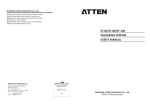
Elevating Work Platform
Operator’s Safety and Maintenance Handbook
For PUSH 6 PRO, PUSH 8 PRO and PUSH 10 PRO
PUSH 6 PRO sn: 01-000025+
PUSH 8 PRO
sn: 01-000368+
PUSH 10 PRO sn: 01-000050+
PN 0120843-EN
July 2012
Table of Contents
Table of Contents
Declaration of Conformity .........................................2
Safety Rules ............................................................ 3
Introduction ...............................................................4
Component Identification .........................................4
Special Limitations ...................................................5
Platform Capacity .................................................5
Manual Force ........................................................5
Lift Level Sensor Interlock ....................................5
Lowering Alarm .....................................................5
Lowering Interrupt ................................................5
Controls and Indicators ............................................6
Lower Controls ........................................................6
Emergency Stop Button .......................................6
Control Selector Switch .........................................6
Ground Operation Button .....................................7
Platform Raise/Lower Buttons ..............................7
Battery Charger Mode Selector .............................7
Upper Controls ........................................................7
Emergency Stop Button .......................................7
Interlock Button ....................................................7
Platform Raise/Lower Buttons ..............................7
Pre-Operation Safety Inspection .............................8
System Function Inspection ....................................9
Operation ................................................................10
Preparing for Operation ..........................................10
Lower Controls ......................................................10
Upper Controls ......................................................10
PUSH PRO -0120843
Platform ................................................................ 11
Raising and Lowering ......................................... 11
Lowering Interrupt ............................................. 11
Component Tray ................................................... 11
Emergency Lowering .............................................. 11
Transporting the Machine .......................................12
Preparing for Transportation ...............................12
Transporting .......................................................12
Lifting With a Forklift ...........................................12
Lifting With a Tail Lift ..........................................12
Maintenance ..........................................................13
Hydraulic Fluid ....................................................13
Check Hydraulic Fluid .........................................13
Battery Maintenance ..........................................13
Battery Charging ................................................13
Inspection and Maintenance Schedule ..................14
Daily Preventative Maintenance Checklist .............15
Preventative Maintenance Report .......................15
General Specifications – PUSH 6 PRO ..................16
General Specifications – PUSH 8 PRO ..................17
General Specifications – PUSH 10 PRO ................18
1
EC DECLARATION OF CONFORMITY
FOR MACHINERY
MACHINERY:
Powered Aerial Platform known as:
Type: Pop Up PUSH PRO
Serial Number: PUSH8-04-xxxxxx
The machine specified above conforms to the following provisions:
Machinery directive 2006/42/EC (using document EC Community Legislation on Machinery and taking
guidance from EN280:2001 + Amendment A2:2009)
Council Directive 2004/108/EC on Electromagnetic Compatibility
Council Directive 2006/95/EC on Low Voltage Equipment Safety
Type approval in accordance with
2006/42/EC performed by:
Powered Access Certification LTD
P. O. Box 98, Windermere
Cumbria, LA23 1WF, UK
Notified Body Identification Number: 0545
E. C. Type Examination Certificate No:
Authorized Representative in
European Union:
The Tanfield Group, PLC
Vigo Centre, Birtley Road
Washington, Tyne & Wear
NE38 9DA, UK
Note: Modification of the specified unit renders this declaration invalid.
2
PUSH PRO -0120843
SAFETY RULES
!
Warning
All personnel shall carefully read, understand and follow all safety rules and operating
instructions before operating or performing maintenance on any Pop Up aerial work platform.
Elektrocution Hazard
Tip Over Hazard
THIS MACHINE IS NOT
INSULATED!
NEVER elevate the platform or
drive the machine while elevated
unless the machine is on a firm,
level surface.
Collision Hazard
Fall Hazard
NEVER position the platform NEVER climb, stand, or
without first checking for sit on platform guardrails
overhead obstructions or other or midrail.
hazards.
USE OF THE AERIAL WORK PLATFORM: This aerial work platform is intended to lift persons and his tools as well
as the material used for the job. It is designed for repair and assembly jobs and assignments at overhead workplaces
(ceilings, buildings etc.). Uses or alterations to the aerial work platform must be approved by Pop Up.
THIS AERIAL WORK PLATFORM IS NOT INSULATED! For this reason it is imperative to keep a safe distance from live
parts of electrical equipment!
Exceeding the specified permissible maximum load is prohibited! See “Platform Capacity” on page 5 for details.
The use and operation of the aerial work platform as a lifting tool or a crane is prohibited!
NEVER exceed the manual force allowed for this machine. See “Manual Force” on page 5 for details.
DISTRIBUTE all platform loads evenly on the platform.
NEVER operate the machine without first surveying the work area for surface hazards such as holes, drop-offs, bumps,
curbs, or debris; and avoiding them.
OPERATE machine only on surfaces capable of supporting wheel loads.
NEVER operate the machine outdoors or indoors when wind speeds exceed 0 m/s (0 mph).
Do not operate the aerial platform in windy or gusty conditions. Do not add anything to or take anything into the aerial
platform that will increase the wind loading such as billboards, banners, flags, etc.
IN CASE OF EMERGENCY push EMERGENCY STOP switch to deactivate all powered functions.
IF ALARM SOUNDS while platform is elevated, STOP, carefully lower platform. Move machine to a firm, level surface.
Climbing up the railing of the platform, standing on or stepping from the platform onto buildings, steel or prefab concrete
structures, etc., is prohibited!
Dismantling the entry gate or other railing components is prohibited! Always make certain that the entry gate is closed!
It is prohibited to keep the entry gate in an open position when the platform is raised!
To extend the height or the range by placing of ladders, scaffolds or similar devices on the platform is prohibited!
NEVER perform service on machine while platform is elevated without blocking elevating assembly.
INSPECT the machine thoroughly for cracked welds, loose or missing hardware, hydraulic leaks, loose wire connections,
and damaged cables or hoses before using.
VERIFY that all labels are in place and legible before using.
NEVER use a machine that is damaged, not functioning properly, or has damaged or missing labels.
To bypass any safety equipment is prohibited and presents a danger for the persons on the aerial work platform and in its
working range.
NEVER charge batteries near sparks or open flame. Charging batteries emit explosive hydrogen gas.
Modifications to the aerial work platform are prohibited or permissible only at the approval by Pop Up.
AFTER USE, secure the work platform from unauthorized use by turning the keyswitch off and removing key.
The driving of MEWP’s on the public highway is subject to national traffic regulations.
Certain inherent risks remain in the operation of this machine despite utilizing proper design practices and safeguarding.
Care must be taken to ensure that the machines meets the requirements of stability during use, transportation, assembly,
dismantling when out of service, testing, or foreseeable breakdowns.
In the event of an accident or breakdown see “Emergency Lowering” on page 11, do not operate the aerial platform if it is
damaged or not functioning properly. Qualified maintenance personnel must correct the problem before putting the aerial
platform back into service.
PUSH PRO -0120843
3
Introduction
Introduction
When contacting Pop Up for service or parts information,
be sure to include the MODEL and SERIAL NUMBERS
from the equipment nameplate. Should the nameplate
be missing, the SERIAL NUMBER is also stamped on
the front of the chassis.
This manual covers the PUSH 6 PRO, PUSH 8 PRO,
and PUSH 10 PRO Aerial Work Platforms.
This manual must be stored on the machine at all
times.
Read, understand and follow all safety rules and
operating instructions before attempting to operate
the machine.
Component Identification
Platform
Upper Controls
Entry Gate
Operators
Manual
Guardrails
Toeboards
Component Tray
Scissors
Structure
Hydraulic Reservoir/Pump • Batteries
Safety Prop
One on Each Side
Forklift Pocket
Chassis
Forklift Pocket
Lower Controls
Brake Lever
Battery Charge
Indicator
Right Side
Emergency
Lowering Lever
Nameplate
Rear
4
PUSH PRO -0120843
Table of Contents
Special Limitations
Elevating the platform is limited to firm, level surfaces
only.
! Danger
The elevating function shall ONLY be used when
the work platform is level and on a firm surface.
The work platform is NOT intended to be pushed over
uneven, rough, or soft terrain.
Platform Capacity
One person and tools may occupy the platform when
the machine is indoors only. The maximum platform
capacity for the aerial platform is stated in the “Specifications” on pages 16 to 18.
! Danger
DO NOT exceed the maximum platform capacity
or the platform occupancy limits for this machine.
Manual Force
Manual force is the force applied by the occupants to
objects such as walls or other structures outside the
work platform.
In zero wind conditions the maximum allowable manual
force is limited to 200 N.
! Danger
DO NOT exceed the maximum amount of manual
force for this machine.
Lift Level Sensor Interlock
The aerial platform lift function is interlocked through a
level sensor system.
If the chassis is tilted more than 2 degrees side-to-side
or front-to-rear, an alarm will sound when the power is
turned on and the lift function will not operate. When
the alarm sounds, only the platform lower function will
operate.
Position the machine on a level surface when the lift
level sensor alarm sounds. When the machine is properly positioned on a level surface, the alarm will not
sound and all functions will be operational.
The lift level sensor system is for added protection and
does not justify operating on anything other than firm,
flat, level surfaces.
Lowering Alarm
When a platform control button is pressed to lower
the platform, the alarm emits a loud beeping sound to
warn personnel in the work area to stand clear.
! Danger
Pinch points exist on the scissors structure. Death
or serious injury will result if the scissors structure
lowers onto personnel within the scissors arms or
under the raised platform. Stand clear while raising
and lowering the platform.
Be careful when lowering the platform. Keep hands
and fingers away from the scissors structures
components.
Lowering Interrupt
When the platform is lowered to about 1.5 m (5′)
lowering stops. The platform will not lower for five
seconds regardless of the control position to allow
personnel to clear the area of the scissors before the
platform completely lowers.
Release the control to reset the lowering function, then
continue to lower the platform.
WIND SPEED
BEAUFORT
RATING
m/s
km/h
ft/s
3
3,4~5,4
12,25~19,4
11,5~17,75
4
5,4~8,0
19,4~28,8
17,75~26,25
12,0~18
5
8,0~10,8
28,8~38,9
26,25~35,5
with leaves start swaying. Wave crests are apparent in
18~24,25 Shrubs
ponds or swamps.
6
10,8~13,9
38,9~50,0
35,5~45,5
24,5~31
7
13,9~17,2
50,0~61,9
45,5~56,5
31.~38,5 Whole trees sway. It is difficult to walk against the wind.
GROUND CONDITIONS
mph
7,5~12,0 Papers and thin branches move, flags wave.
Dust is raised, paper whirls up, and small branches sway.
Tree branches move. Power lines whistle. It is difficult to open an
umbrella.
Figure 1 – Beaufort Scale
PUSH PRO -0120843
5
Controls and Indicators
Controls and Indicators
The operator shall know the location of each control
and indicator and have a thorough knowledge of the
function and operation of each before attempting to
operate the machine.
1
3
2
4
5
! Danger
Pinch points may exist between moving
components. Death or serious injury will result
from becoming trapped between components,
buildings, structures, or other obstacles. Make
sure all personnel stand clear while operating the
aerial platform.
• Controls to position the platform are located on
the lower control panel on the chassis and on the
upper control panel in the platform.
6
Lower Controls
The lower controls (refer to Figure 2) are located on
the right side of the chassis.
7
10
8
9
The following are located on the lower control panel:
11
Figure 2 – Lower Controls and Indicators
1. Tilt/lowering alarm
2. Battery charge indicator
3. 110V battery charger plug
4. Battery charger mode selector
5. 230V/240V battery charger plug
6. Tray latch
7. Ground operation button
8. Platform raise button
9. Emergency stop button
10. Platform lower button
11. Control selector switch
• Emergency stop button
• Control selector switch
• Ground operation button
• Platform raise/lower buttons
• Battery charger selector/plugs/indicator
! Warning
The aerial platform is free to move when the
brakes are released. Death or serious injury can
result. Engage the brakes before operating the
aerial platform.
Emergency Stop Button
The emergency stop is a two-position red push
button.
• Push the button inward to disconnect power to all
control circuits.
15
16
13
• Pull the button outward to restore power.
Control Selector Switch
Insert the key into the control selector switch.
• Turn the switch to the lower controls position to
operate aerial platform functions from the lower
controls. The upper controls will not operate while
the control selector is in the lower position.
14
12
• Turn the switch to the upper controls position to
operate the aerial platform functions from the
upper controls.
• In the center position, aerial platform functions will
not operate from the lower or upper controls.
Figure 3 – Upper Controls and Indicators
12. Interlock button
13. Battery condition indicator
14. Platform lower button
15. Platform raise button
16. Emergency stop button
6
PUSH PRO -0120843
Controls and Indicators
Ground Operation Button
The ground operation button prevents platform
movement if the platform raise or lower button is
accidentally pressed. This switch is spring returned to
the off position.
Press and hold the ground operation switch inward
continually to operate the machine from the lower
controls.
Platform Raise/Lower Buttons
The platform raise/lower buttons are used to raise or
lower the platform. The buttons are spring returned to
the off position.
Emergency Stop Button
The emergency stop is a two-position, red push button
on the right side of the upper control panel.
• Push the button inward to disconnect power from
all control circuits at the upper controls.
• Twist the button clockwise to restore power.
Push the button in when the upper controls are not
in use to help protect against unintentional platform
operation.
• Press and hold the platform raise button to raise
the platform.
Interlock Button
The interlock button prevents platform movement if the
platform raise or lower button is accidentally pressed.
This switch is spring returned to the off position.
• Press and hold the platform lower button to lower
the platform.
Press and hold the interlock button inward continually
to operate the machine from the upper controls.
• An alarm will sound as the platform lowers.
Battery Charger Mode Selector
The battery charger may be operated on either 110V
or 230V/240V electrical circuits.
Platform Raise/Lower Buttons
The platform raise/lower buttons are used to raise or
lower the platform. The buttons are spring returned to
the off position.
• Move the toggle switch to the left for operation on
110V circuits.
• Press and hold the platform raise button to raise
the platform.
• Move the toggle switch to the right for operation on
230V/240V circuits.
• Press and hold the platform lower button to lower
the platform.
• In the middle position, the battery charger is off
and will not charge.
• An alarm will sound as the platform lowers.
Upper Controls
The upper controls (refer to Figure 3) are located on
the control panel at the front of the platform.
The following controls are located on the upper control
panel:
• Interlock button
• Battery condition indicator
• Platform raise/lower buttons
• Emergency stop button
! Warning
The aerial platform is free to move when the
brakes are released. Death or serious injury can
result. Engage the brakes before operating the
aerial platform.
PUSH PRO -0120843
7
Pre-Operation Safety Inspection
Pre-Operation Safety Inspection
Note
Carefully read, understand and follow all safety rules,
operating instructions, labels and National Safety
Instructions/Requirements.
1. Open the tray and inspect for damage, fluid leaks
or missing parts daily.
2. Check daily the level of the hydraulic fluid with
the platform fully lowered. The fluid level must be
within 6 mm (¼″) of the top of the fill hole. Add
recommended hydraulic fluid if necessary. See
“Specifications” on pages 16 to 18.
3. Check weekly that the fluid level in the batteries
is correct. See “Battery Maintenance” on page
15.
4. Verify that the batteries are charged daily.
5. Check daily that the AC extension cord has been
disconnected from the outlet on the side of the
chassis.
6. Inspect the brakes daily on the rear castor wheels
for proper operation. Step down on the brake
levers and verify that the machine will not move.
7. Check daily that all guardrails are in place and all
fasteners are properly tightened.
8. Inspect the machine thoroughly each day for
cracked welds and structural damage, loose or
missing hardware, hydraulic leaks, damaged
control cable and loose wire connections.
8
PUSH PRO -0120843
System Function Inspection
System Function Inspection
6. Test the emergency lowering system for proper
operation.
! Warning
7. Push the Lower Control Emergency Stop Button
to check for proper operation. All machine
functions should be disabled. Pull the Lower
Control Emergency Stop Button outward to
resume.
Refer to “Controls and Indicators” on page 6 for the
locations of various controls and indicators.
STAND CLEAR of the work platform while
performing the following checks.
Before operating the machine, survey the work
area for surface hazards such as holes, drop-offs,
bumps and debris.
Check in ALL directions, including above the
work platform, for obstructions and electrical
conductors.
1. Move the machine, if necessary, to
unobstructed area to allow for full elevation.
an
2. Pull the Lower Control Emergency Stop Switch to
the ON position.
3. Turn the Upper Control Emergency Stop Switch
clockwise to the ON position.
4. Visually inspect the scissors structure, lift cylinder,
and hoses for cracked welds and structural
damage, loose hardware, hydraulic leaks, loose
wire connections, and erratic operation. Check
for missing or loose parts.
8. Enter the platform and close the gate.
9. Check that the route is clear of obstacles
(persons, obstructions, debris), is level, and is
capable of supporting the wheel loads.
10.Test each machine function from the upper control
station by engaging the interlock and operating
the function controls (refer to Figure 3).
11. Push the Upper Control Emergency Stop Button
to check for proper operation. All machine
functions should be disabled. Turn the Upper
Control Emergency Stop Button clockwise to
resume.
12.Check to ensure that the Auto Brake system
works correctly by raising the machine slightly
from the lower controls. Check that the brake is
engaged against the rear castor wheels. Check
to make sure the machine will not move when
elevated.
5. Press and hold the ground operation button
inward. Test each machine function from the
lower control station (refer to Figure 2).
PUSH PRO -0120843
9
Operation
Operation
The aerial platform may be operated from either the
lower or upper controls.
4. Step down on each of the brake levers to lock the
rear wheels in position. Verify that the brakes are
engaged before entering the platform.
! Danger
The aerial platform is not electrically insulated.
Death or serious injury will result from contact
with, or inadequate clearance from, an energized
conductor. Do not go closer than the minimum
safe approach distance as defined by national
safety regulations.
Pinch points may exist between moving
components. Death or serious injury will result
from becoming trapped between components,
buildings, structures, or other obstacles. Make
sure there is sufficient clearance around the
machine before moving the chassis or platform.
Allow sufficient room and time to stop movement
to avoid contact with structures or other hazards.
The aerial platform can tip over if it becomes
unstable. Death or serious injury will result from
a tip-over accident. Operate the aerial platform on
a firm, flat, level surface. Engage both of the rear
brakes befor entering the platform. Do not position
the aerial platform for elevated use near any dropoff, hole, slope, soft or uneven ground, or other
tip-over hazard. Do not raise the platform in wind
speeds above 0 m/s.
The platform rated work load is the total weight of the
personnel and equipment that may be lifted in the
platform.
The work loads are stated on the platform rating
placard at the entrance to the platform.
! Danger
Lower Controls
The platform raise and lower functions may be
operated from the lower controls. The lower controls
may be used for initial set up of the aerial platform, and
for testing and inspection.
Use the following procedure to raise or lower the
platform using the lower controls.
1. Pull the emergency stop button outward (refer to
Figure 2).
2. Insert the key into the control selector switch and
turn the switch to the lower controls position.
3. Press and hold the ground operation button
inward.
• To raise the platform,
platform raise button.
press and hold the
• To lower the platform, press and hold the
platform lower button.
4. Release the button to stop movement.
Upper Controls
Before operating the upper controls, properly set up
the aerial platform as described under Preparing for
Operation.
Use the following procedure to operate the aerial
platform from the upper controls:
The aerial platform can tip over if it becomes
unstable. Death or serious injury will result from
a tip-over accident. Do not exceed the capacity
values indicated on the platform rating placard.
Capacity values indicate the rated lifting capacity and
do not indicate aerial platform stability.
The operator bears ultimate responsibility for ensuring
that the aerial platform is properly set up for the
particular conditions encountered.
Preparing for Operation
Use the following procedure to prepare the aerial
platform for operation:
1. Perform a pre-operation safety and system
function inspection.
2. Close and latch the component tray.
3. Position the machine in the work place and make
certain the area is flat and horizontal.
10
PUSH PRO -0120843
Operation
1. From the lower controls, pull the emergency stop
button outward (refer to Figure 2).
2. Insert the key into the control selector switch and
turn the switch to the upper controls position.
Note
The upper controls will not operate while the control
selector is in the lower position.
3. Enter the platform and secure the gate.
4. From the upper controls, turn the emergency
stop button clockwise to the on position (refer to
Figure 3).
5. The platform may be raised and lowered from the
upper controls.
Platform
Use care when entering and exiting the platform to
avoid slipping and/or falling. Securely close the safety
gate when the platform is occupied.
Raising and Lowering
Press and hold the interlock button on the left side of
the upper control box.
• To raise the platform, press and hold the platform
raise button until the desired height is reached.
• To lower the platform, press and hold the platform
lower button until the desired height is reached.
Lowering Interrupt
When the platform is lowered to about 1.5 m (5′)
lowering stops. The platform will not lower for five
seconds regardless of the joystick position.
Release the platform lower button to reset the lowering
function, then continue to lower the platform.
PUSH PRO -0120843
Component Tray
Batteries and hydraulic components are enclosed in
the component tray on the left side of the chassis.
! Danger
The aerial platform can tip over if it becomes
unstable. Death or serious injury can result from
a tip-over accident. Do not open the tray when the
platform is elevated.
To open the tray, lift up on the tray latch and pull the
tray open.
Emergency Lowering
Use the following procedure to operate the emergency
lowering system.
! Warning
The potential for an accident increases when safety
devices do not function properly. Death or serious
injury can result from such accidents. Immediately
push the emergency stop button inward to disable
the control system before using the emergency
lowering system in the event of an emergency.
1. Immediately push the emergency stop button
inward to disable the control system in the event
of an emergency.
2. Make sure there is nothing in the way to obstruct
the platform when it lowers.
• Push downward on the lever to lower the
platform.
3. Make certain the lever/handle is fully released
and the emergency lowering valve is fully closed
before operating the aerial platform.
11
Transporting the Machine
Transporting the Machine
Preparing for Transportation
Use the following procedure to prepare the aerial platform for transportation.
Lifting With a Tail Lift
Use the following procedure to lift the aerial platform
with a forklift.
1. Properly stow the aerial platform.
1. Remove any unnecessary tools, materials, or
other loose objects from the platform.
2. Remove all personnel, tools, materials, or other
loose objects from the platform.
2. Close and latch the component tray.
3. Position the aerial platform on the tail lift.
Transporting
The equipment used to load, unload, and transport
the aerial platform must have adequate capacity. The
empty vehicle weight is listed in “Specifications” on
pages 16 to 18 and is stamped on the serial number
placard.
4. Engage the brakes on both of the rear wheels.
5. Carefully raise the lift and position the aerial
platform in the transport vehicle.
6. Secure the machine to the transport vehicle using
straps through the fork lift pockets.
The user assumes all responsibility for:
• Choosing the proper method of transportation.
• Choosing the proper selection and use of
transportation and tie-down devices.
• Making sure the equipment used is capable of
supporting the weight of the aerial platform.
• Making sure all manufacturer’s instructions and
warnings, regulations and safety rules of their
employer, the DOT, and/or any other state or
federal law are followed.
Lifting With a Forklift
Use the following procedure to lift the aerial platform
with a forklift.
1. Properly stow the aerial platform.
2. Engage the brakes on both of the rear wheels.
3. Remove all personnel, tools, materials, or other
loose objects from the platform.
4. Insert the forklift forks into the pockets on either
side of the machine.
! Caution
Lifting the aerial platform with the forklift forks
positioned improperly can produce enough force
to damage machine components. When lifting the
machine with a forklift, only use the designated lift
points.
5. Do not raise the aerial platform higher than
necessary to transport it. Drive the forklift slowly
and carefully when transporting the aerial
platform.
12
PUSH PRO -0120843
Maintenance
Maintenance
Check Hydraulic Fluid
! Warning
Always block the elevating assembly whenever
it is necessary to perform maintenance while the
platform is elevated.
Use the following procedure to properly position the
safety props:
1. Remove all tools and material from the platform.
2. Using the lower controls, raise the platform until
the open distance on the chassis is wide enough
to position the safety props. Refer to Figure 5.
1. Make sure that the platform is fully lowered.
2. Visually check to make sure the fluid is within
6 mm (¼″) of the top of the fill hole.
3. If necessary, remove the filler cap and add fluid of
the proper type. Replace the cap making sure it
is tightly in place. Refer to “Specifications” pages
16 to18.
Battery Maintenance
! Warning
Hazard of explosive gas mixture. Keep sparks,
flame, and smoking material away from the
battery.
Always wear safety glasses when working near
the battery. Battery fluid is highly corrosive.
Thoroughly rinse away any spilled fluid with clean
water.
Safety Prop
Always replace the battery with a manufacturer
approved replacement.
• Check the battery fluid level weekly, especially if
the machine is being used in a warm, dry climate.
Figure 5 – Safety Props
3. Rotate the safety props downward from the
storage position to the support position.
• If electrolyte level is lower than 6 mm (¼″) above
the plates add distilled water only. DO NOT use tap
water with high mineral content, as it will shorten
battery life.
• Keep the terminals and top of the battery clean.
4. Remove hands and arms from the scissors area.
• Refer to the Service Manual to extend battery life
and for complete service instructions.
5. Lower the platform until the scissors are
supported by the safety props.
! Warning
Hydraulic Fluid
The hydraulic fluid reservoir is located in the component
tray. Refer to Figure 6.
Reservoir Fill Cap
Always use manufacturer approved replacement
parts.
Battery Charging
Charge the battery at the end of each work shift or
sooner if the battery has been discharged.
Note: The PUSH series has a built in feature whereby
power is cut to the machine when the battery level
reaches 94.5% or 11.34v of the original 12v supply,
this is to prevent excessive wear or damge to the battery. The machine should immediately be placed on
charge if this occurs.
! Warning
Charge the battery in a well ventilated area.
Do not charge the battery when the machine is
near a source of sparks or flames.
Figure 6 – Component Tray
Note
Never add fluid if the platform is elevated.
PUSH PRO -0120843
Permanent damage to the battery will result if
the battery is not immediately recharged after
discharging.
Never disconnect the cables from the battery when
the charger is operating.
13
Inspection and Maintenance Schedule
Keep the charger dry.
1. At the lower controls, turn the control selector
switch to the off position.
2. Open the component tray to access the battery.
Remove the caps from the battery.
3. Visually check the battery fluid level making sure
the level is within 6 mm (¼″) of the bottom of
the filler neck inside each hole. If needed, add
distilled water.
4. Tightly replace the caps on each battery and
replace and latch the battery tray covers.
5. Place the battery charger mode selector, on the
lower control panel, in the appropriate position
for power source being used.
• Move the toggle switch to the left for operation
on 110V circuits.
• Move the toggle switch to the right for operation
on 230V240V circuits.
6. Plug the battery charger into a properly grounded
outlet (100-240 volt AC, 50/60 Hz) using a 3
conductor, 1.5 mm (12 gauge) or larger extension
cord. The extension cord must be as short as
possible and in good electrical condition.
7. Visually inspect the battery charge indicator for
proper charging rate. The LED’s are visible on
the left side of the lower controls. Refer to Figure
7 for the function of each LED. The battery should
be fully charged when the 95% LED is on.
Figure 7 – Battery Charge Indicator
8. Leave the battery charger plugged in until it shuts
itself off.
Note
If the charging cycle exceeds 16 hours without the
battery being fully recharged, unplug the charger and
have the battery checked.
9. After the battery charger turns itself off, it is not
necessary to immediately unplug the extension
cord from the battery charger. The charger will
monitor the charge state of the battery and
recharge them if the voltage drops off.
10.Slide the component tray open to access the
battery. Remove the caps from the battery.
11. Visually check the battery fluid level making sure
the level is within 6 mm (¼″) of the bottom of
the filler neck inside each hole. If needed, add
distilled water.
12.Tightly replace the caps on the battery and close
and latch the component tray.
Inspection and Maintenance Schedule
! Caution
Frequency and extent of periodic examinations
may depend on national regulations.
The Complete Inspection consists of periodic visual
and operational checks, along with periodic minor
adjustments that assure proper performance. Daily
inspection will prevent abnormal wear and prolong the
life of all systems. The inspection and maintenance
schedule should be performed at the specified intervals
and after prolonged periods of storage before returning
the machine to service. Inspection and maintenance
shall be performed by personnel who are trained and
familiar with mechanical and electrical procedures.
! Warning
Steady Red When Charger
Is Plugged In
25% Charge
95% Charge
Flashes During Charging
14
Before performing preventative maintenance,
familiarize yourself with the operation of the
machine. Always block the scissors structure
whenever it is necessary to perform maintenance
while the platform is elevated.
The daily preventative maintenance checklist has
been designed for machine service and maintenance.
Please photocopy the Daily Preventative Maintenance
Checklist and use the checklist when inspecting the
machine.
PUSH PRO -0120843
Daily Preventative Maintenance Checklist
Daily Preventative Maintenance Checklist
Preventative Maintenance Report
Date:_____________________________________
Serial No:__________________________________
Owner:____________________________________
Serviced By: _______________________________
Model No: _________________________________
Item
Inspect For
Operator’s Manual
Y
N
R
In manual holder, all pages readable and intact
Electrical System
Battery terminals
Clean, connectors tight
Battery charge indicator
Proper operation
Battery charger
Proper operation
Cables and wiring harness
No wear or physical damage
Hydraulic System
Fluid level
Between full and add marks with platform
stowed
Hoses, tubes and fittings
No leaks, all fittings tight
Castors
Good condition, no damage/smooth movement
Manual Brakes
Proper operation, no damage or deformation
Lower Control Station
Operating controls
Proper operation
Emergency stop
Shuts off lower controls/proper operation
Lowering alarm and interrupt
Sounds when platform lowers/proper operation
Emergency Lowering
Proper operation
Safety Prop
No damage or deformation
Structures
Weldments – Scissors, chassis, steps,
platform, etc.
Welds intact, no damage or deformation
Platform slide rollers
In place, no damage or deformation
Fasteners
In place, tight, and no damage
Upper Control Station
Guardrail system
Welds intact, no damage or deformation
All fasteners in place, no loose or missing parts
Platform floor
No damage or deformation
Clean to prevent slip and fall hazards
Entry gate
Proper operation, no damage or deformation
Operating controls
Proper operation/raise and lower
Lowering delay
Proper operation, limit switch delays lowering
Emergency stop
Shuts off upper controls
Operation and Safety Decals
In place and readable
Maintenance Table Key: Y = Yes/Acceptable, N = No/Not Acceptable, R = Repaired/Acceptable
PUSH PRO -0120843
15
Specifications
General Specifications – PUSH 6 PRO
Aerial Platform
Working height Maximum platform height Wheelbase Ground clearance Maximum wheel load Maximum ground pressure Floor loading Weight, EVW
Approximate Stowed width Stowed length Stowed height 3.83 m
1.83 m
1m
1.9 cm
267 kg
10.4 kg/cm²
782 kg/m²
295 kg
76.2 cm
1.23 m
1.59 m
Platform
Dimensions 51.3 cm x 109 cm
Guardrail height 110.4 cm
Toeboard height 15.3 cm
Rated work load 240 kg
Maximum number of occupants 1 indoors
Function Speed
Platform raise Platform lower 6 to 10 seconds
6 to 10 seconds
Lift Level Sensor Interlock
Side-to-side Front-to-rear Tires
16
2 degrees
2 degrees
Electrical System
Voltage 12 V DC negative chassis ground
Source One - 12 V 105 amp hour battery
Fluid recommended distilled water
Charger 15 amp
Hydraulic System
Maximum pressure 19,305 kPa
Pressure Relief Valve Setting
2,000 psi
Reservoir capacity 3.78 l
System capacity 3.78 l
Maximum operating temperature 71°C (160°F)
Hydraulic fluid recommended
Above -13°C (10°F) ISO VG32 (Mobil DTE-13M)
Below -13°C (10°F) ISO VG15 (Mobil DTE-11M)
Ambient Air Temperature Operating Range
Celsius -18°C to 43°C
Fahrenheit 0°F to 110°F
Maximum Wind Speed
Gust or steady Vibration
Sound Pressure Level
At work station 0 m/s
less than 2.5 m/sec²
below 70 dB(A)
Nonmarking solid rubber
PUSH PRO -0120843
Specifications
General Specifications – PUSH 8 PRO
Aerial Platform
Working height Maximum platform height Wheelbase Ground clearance Maximum wheel load Maximum ground pressure Floor loading Weight, EVW
Approximate Stowed width Stowed length Stowed height 4.43 m
2.43 m
1m
1.9 cm
287 kg
11.1 kg/cm²
835 kg/m²
331 kg
76.2 cm
1.23 m
1.67 m
Platform
Dimensions 51.3 cm x 109 cm
Guardrail height 110.4 cm
Toeboard height 15.3 cm
Rated work load 240 kg
Maximum number of occupants 1 indoors
Function Speed
Platform raise Platform lower 6 to 12 seconds
8 to12 seconds
Lift Level Sensor Interlock
Side-to-side Front-to-rear Tires
PUSH PRO -0120843
2 degrees
2 degrees
Electrical System
Voltage 12 V DC negative chassis ground
Source One - 12 V 105 amp hour battery
Fluid recommended distilled water
Charger 15 amp
Hydraulic System
Maximum pressure 19 305 kPa
Pressure Relief Valve Setting
2,000 psi
Reservoir capacity 3.78 l
System capacity 3.78 l
Maximum operating temperature 71°C (160°F)
Hydraulic fluid recommended
Above -13°C (10°F) ISO VG32 (Mobil DTE-13M)
Below -13°C (10°F) ISO VG15 (Mobil DTE-11M)
Ambient Air Temperature Operating Range
Celsius -18°C to 43°C
Fahrenheit 0°F to 110°F
Maximum Wind Speed
Gust or steady Vibration
Sound Pressure Level
At work station 0 m/s
less than 2.5 m/sec²
below 70 dB(A)
Nonmarking solid rubber
17
Specifications
General Specifications – PUSH 10 PRO
Aerial Platform
Working height Maximum platform height Wheelbase Ground clearance Maximum wheel load Maximum ground pressure Floor loading Weight, EVW
Approximate Stowed width Stowed length Stowed height 5m
3.0 m
1m
1.9 cm
293 kg
11.4 kg/cm²
855 kg/m²
345 kg
76.2 cm
1.23 m
1.67 m
Platform
Dimensions 51.3 cm x 109 cm
Guardrail height 110.4 cm
Toeboard height 15.3 cm
Rated work load 240 kg
Maximum number of occupants 1 indoors
Function Speed
Platform raise Platform lower 10 to14 seconds
10 to14 seconds
Lift Level Sensor Interlock
Side-to-side Front-to-rear Tires
18
2 degrees
2 degrees
Electrical System
Voltage 12 V DC negative chassis ground
Source One - 12 V 105 amp hour battery
Fluid recommended distilled water
Charger 15 amp
Hydraulic System
Maximum pressure 19,305 kPa
Pressure Relief Valve Setting
2,000 psi
Reservoir capacity 3.78 l
System capacity 3.78 l
Maximum operating temperature 71°C (160°F)
Hydraulic fluid recommended
Above -13°C (10°F) ISO VG32 (Mobil DTE-13M)
Below -13°C (10°F) ISO VG15 (Mobil DTE-11M)
Ambient Air Temperature Operating Range
Celsius -18°C to 43°C
Fahrenheit 0°F to 110°F
Maximum Wind Speed
Gust or steady Vibration Sound Pressure Level
At work station
0 m/s
less than 2.5 m/sec²
below 70 dB(A)
Nonmarking solid rubber
PUSH PRO -0120843
POP-UP
Vigo Centre
Birtley Road
Washington
Tyne & Wear
NE38 9DA
UK
Tel +44 (0)845 1550 057
Fax +44 (0)845 1557 756