1
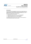
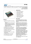
UM1868
User manual
BlueNRG and BlueNRG-MS information register (IFR)
Introduction
This user manual describes the information register (IFR) of the BlueNRG and BlueNRG-MS devices
and provides related programming instructions.
March 2015
DocID027570 Rev 1
1/19
www.st.com
Contents
UM1868
Contents
1
Information register sector ............................................................. 3
1.1
2
3
IFR data regions................................................................................ 4
1.1.1
Cold boot region ................................................................................. 4
1.1.2
Hot boot region ................................................................................... 4
1.1.3
Configuration parameters region ........................................................ 5
BlueNRG GUI IFR utility .................................................................. 6
2.1
IFR View/Edit view ............................................................................ 7
2.2
IFR memory view ............................................................................ 11
2.3
IFR C view....................................................................................... 12
BlueNRG IFR programming steps ................................................ 14
3.1
BlueNRG GUI IFR programming ..................................................... 14
3.2
BlueNRG IFR Updater demonstration application ........................... 15
4
List of acronyms ............................................................................ 16
5
6
Related documentation and references ....................................... 17
Revision history ............................................................................ 18
2/19
DocID027570 Rev 1
UM1868
1
Information register sector
Information register sector
The BlueNRG and BlueNRG-MS firmware stacks use a table of configurable parameters
which allows some key parameters of their devices to be properly configured. Such key
parameters include high-speed crystal time, low-speed crystal type, frequency and period,
and stack mode. The configurable parameters table resides in a sector of the Flash called
the information register (IFR).
Figure 1 and Figure 2 below show the Flash layouts of the BlueNRG and BlueNRG-MS
devices. Specific software such as the Updater, and the BlueNRG and BlueNRG-MS
firmware stacks are indicated in addition to the area where the IFR data are stored. The
IFR sector comprises 2 Kbytes of Flash memory and normally contains device
configuration parameters. However, since the configuration parameters use up only 192
bytes, the remainder of the IFR sector contains some code for the BlueNRG while it is left
empty (0xFFFFFFFF) for the BlueNRG-MS. The address of IFR sector is 0x10020000.
Figure 1: BlueNRG Flash layout
Updater (in FLASH1, 2 Kbytes)
BlueNRG firmware stack (in FLASH1, 62 Kbytes)
BlueNRG firmware stack + IFR data (in FLASH2, 2 Kbytes)
Figure 2: BlueNRG-MS Flash layout
BlueNRG-MS firmware stack (in FLASH1, 64 Kbytes)
BlueNRG-MS IFR data (in FLASH2, last 192 bytes)
Note: Only IFR data can be carefully configured. The user must not change the content of
all the other Flash regions outside the IFR data (except when a new valid firmware stack is
loaded).
DocID027570 Rev 1
3/19
Information register sector
1.1
UM1868
IFR data regions
The IFR sector is divided into three regions (see Figure 3):
1.
2.
3.
Cold boot table region (COLD_ANA_CONFIG_TABLE)
Hot boot table region (HOT_ANA_CONFIG_TABLE)
Configuration parameters region (IFR_DATA_CONFIG)
Figure 3: IFR regions
Note: All IFR parameters that are configurable can be changed with the BlueNRG IFR
utility "View/Edit" view (see Section 2: "BlueNRG GUI IFR utility")
1.1.1
Cold boot region
The cold boot region (COLD_ANA_CONFIG_TABLE) contains analog configurations that
are loaded on hardware reset and power-on-reset (POR). This region configures registers
that maintain analog configurations while in sleep mode (e.g. clock configuration). The
information to do this is provided through default IFR data configuration files or it can
automatically be generated by the BlueNRG GUI IFR utility according to the hardware
configuration (e.g. crystals on the board).
1.1.2
Hot boot region
The hot boot region (HOT_ANA_CONFIG_TABLE) contains analog configurations that are
loaded every time the device comes out of sleep mode. This information is provided by
STMicroelectronics.
4/19
DocID027570 Rev 1
UM1868
1.1.3
Information register sector
Configuration parameters region
The configuration parameters region (IFR_DATA_CONFIG) contains the information and
configuration parameters shown in Figure 4.
Figure 4: IFR configuration parameters region
Address 31 30 29 28 27 26 25 24 23 22 21 20 19 18 17 16 15 14 13 12 11 10 9 8 7 6 5 4 3 2
100207 FC
FREE
100207 F8
FREE
100207 F4
FREE
100207 F0
FREE
100207 EC
FREE
100207 E8
Day
Month
Year
RESERVED
100207 E4
UID
100207 E0
RESERVED
HS startup time
100207 DC
RESERVED
Master SCA
Slave SCA
100207 D8
LS Crystal Freq
100207 D4
LS Crystal Period
100207 D0
Max connection event time
RESERVED
100207 CC
RESERVED
100207 C8
100207 C4
RESERVED
100207 C0
RESERVED
GPIO Config
Stack Mode
1
0
Used by the Stack
Information
Reserved
DocID027570 Rev 1
5/19
BlueNRG GUI IFR utility
2
UM1868
BlueNRG GUI IFR utility
The BlueNRG GUI IFR utility is a tool that allows customers to define the IFR data in a
controlled way. Using this utility is the only way to define IFR data according to a customers
needs. The utility supports both BlueNRG and BlueNRG-MS devices and it provides the
following windows:
•
•
•
View/Edit view: displays the IFR regions with related fields and description. The user
can modify some of these fields according to his needs.
Memory view: displays the IFR fields with memory addresses and related values that
are generated by the BlueNRG GUI according to specified values on View/Edit view.
C view: displays the C language structure related to the IFR configuration data region
matching the View/Edit and Memory views.
Some of the following general utilities are also available:
•
•
•
•
•
6/19
A tab for selecting either the BlueNRG or the BlueNRG-MS device
A load button to allow a configuration file to be loaded
A save button to allow the current parameters to be saved into a configuration file
A read button to allow IFR content from the device to be read
A write button to allow the displayed IFR configuration to be written into the device IFR
DocID027570 Rev 1
UM1868
2.1
BlueNRG GUI IFR utility
IFR View/Edit view
The BlueNRG GUI IFR utility View/Edit view allows the register fields that are written into
the device IFR to be displayed and allows the different versions of the device IFR
configurations to be distinguished. The user can carefully modify the editable values and
retrieve these changes in both the Memory and C views. The BlueNRG GUI IFR View/Edit
view contains the tabs shown in Figure 5 below.
Figure 5: BlueNRG GUI IFR View/Edit view tabs
DocID027570 Rev 1
7/19
BlueNRG GUI IFR utility
UM1868
The tables below show the available IFR View/Edit window fields.
Table 1: Crystal selection
Field name
Description
Supported value
High-speed crystal
Select which crystal to be used
16 MHz
32 MHz
Low-speed source
Select which oscillator to be used
32 kHz crystal oscillator
Internal ring oscillator (without crystal)
Table 2: Power management
8/19
Field name
Description
10 µH SMPS inductor
Select this field if using SMPS with 10 µH inductor
4.7 µH SMPS inductor
Select this field if using SMPS with 4.7 µH inductor
(valid only for BlueNRG-MS)
Force SMPS off
Forces SMPS pins off. It may be used to disable the SMPS pin on the
WLCSP package or even on the QFN package when NO_SMPS pin is
connected to GND.
DocID027570 Rev 1
UM1868
BlueNRG GUI IFR utility
Table 3: Configuration data
Field name
Description
Supported value
Stack mode
Indicates stack mode. This
value (if valid) overrides the
STACK default (0x02)
Mode 1: slave/master, one connection only,
small GATT database (RAM2 off during sleep)
Mode 2: slave/master, one connection only,
large GATT database (RAM2 on during sleep)
Mode 3: up to eight connections, master only
(BlueNRG), master/slave (BlueNRG-MS), small
GATT database (RAM2 on during sleep)
Day
Allows a date (day) to be
associated with a specific
BlueNRG IFR configuration
[1-31]
Month
Allows a date (month) to be
associated with a specific
BlueNRG IFR configuration
[1-12]
Year
Allows a date (year) to be
associated with a specific
BlueNRG IFR configuration
[0-99]
High-speed
startup time
Startup time for the highspeed crystal
(time unit = 2.4414 µsec)
Ranges from 512 µs to 1953 µs. It can be
measured using the XTAL_startup_TEST
described in AN4494 “Bringing up the BlueNRG”
Slave SCA
Slave sleep clock accuracy,
depends on low-speed
oscillator
[10-1500] ppm
Master SCA
Master sleep clock accuracy,
depends on low-speed
oscillator
20, 30, 50, 75, 100, 150, 250, 500 ppm
Low-speed
crystal period
Low-speed crystal period
(read-only value defined in
BlueNRG GUI)
Low-speed
crystal frequency
Low-speed crystal frequency
(read-only value defined in
BlueNRG GUI)
If 0xFFFFFFFF autocalibration is enabled
Maximum
connection event
time
Maximum duration of a
connection event in the slave
(1)
(time unit = 2.4414 µsec)
[0-4] s
GPIO
configuration
Sets GPIOs in a given
configuration for special
(1)
functions
Disabled: GPIOs in high impedance
Active state on TEST1: high when device is
active because of SPI or radio activity
UID
Allows existing UID with
given 32-bit number to be
(1)
overwritten.
Free
Allows IFR free addresses
with user-defined values to
(1)
be configured
Notes:
(1)
Available by selecting "Advanced" button
DocID027570 Rev 1
9/19
BlueNRG GUI IFR utility
UM1868
Table 4: Test modes
Field name
Description
Notes
User mode
Normal mode
Low-speed
crystal measure
Output signal from 32 kHz crystal
oscillator on TEST9 pin
Refer to LSOSC_center_TEST described
in AN4494 “Bringing up the BlueNRG"
High-speed
startup time
measure
Output signals on TEST8 and
TEST9 pins for XTAL startup
measurement
Refer to XTAL_center_TEST described in
AN4494 “Bringing up the BlueNRG”
In addition, the Cold and Hot tables show the following:
•
•
10/19
Cold table: shows the cold boot region (COLD_ANA_CONFIG_TABLE) register
values. This information cannot be directly changed by the user. Correct data is
automatically generated upon selection of correct configuration values, like the
high-speed crystal, low-speed crystal, or SMSP configuration.
Hot table: shows the hot boot region (HOT_ANA_CONFIG_TABLE) register values.
This information cannot be changed by the user.
DocID027570 Rev 1
UM1868
2.2
BlueNRG GUI IFR utility
IFR memory view
The BlueNRG GUI IFR utility memory view allows the IFR addresses, with related values
as defined on the IFR regions view, to be dispayed.
Figure 6: BlueNRG GUI IFR memory view
DocID027570 Rev 1
11/19
BlueNRG GUI IFR utility
2.3
UM1868
IFR C view
The BlueNRG GUI C-source view provides the C language structure, related to the IFR
configuration data region and matching the IFR View/Edit view. The BlueNRG GUI
C-source view is automatically updated with the values loaded/configured on the BlueNRG
GUI IFR utility View/Edit view. It can be used to generate a C-language structure that can
be used within the BlueNRG IFR Updater demonstration firmware application with the
option BLUENRG_CONFIG = BLUENRG_CUSTOM_CONFIG. This application can be
customized and used by the customer during PCB manufacturing to customize the IFR
data.
12/19
DocID027570 Rev 1
UM1868
BlueNRG GUI IFR utility
Figure 7: BlueNRG GUI IFR C-source view
DocID027570 Rev 1
13/19
BlueNRG IFR programming steps
3
UM1868
BlueNRG IFR programming steps
Regarding IFR programming, two procedures are available:
•
•
The BlueNRG GUI IFR utility which is useful for bench testing and bringing up
application PCBs.
Dedicated external microcontroller firmware based on the BlueNRG IFR ACI utility
APIs, available within the latest available BlueNRG DK software package. This
example firmware can be used during customer PCB manufacturing.
Some reference IFR data configuration files (*.dat) are available with the BlueNRG DK
software package. These files can be used as a starting point to customize the IFR based
on customer needs.
3.1
BlueNRG GUI IFR programming
The BlueNRG IFR can be programmed by following the steps below:
•
•
•
•
•
•
•
14/19
Open the BlueNRG GUI available on the BlueNRG DK 1.7.0 or later software package
Connect the BlueNRG or BlueNRG-MS platform to a PC USB port
Load the prebuilt Virtual COM image BlueNRG_VCOM_1_x.hex available on the
Firmware\STM32L1_prebuilt_images using the GUI, tools, and Flash motherboard
firmware provided that the BlueNRG or BlueNRG-MS platform is in DFU mode (on the
Projects\Project\Virtual_COM_Port folder, an IAR project is also available for building
and downloading the Virtual COM image through JTAG).
On the BlueNRG GUI, select the associated COM port and click on the "Open" button
Select the Tools, BlueNRG IFR... utility and the View/Edit tab
Customize the IFR fields according to the user's needs or click on the “Load” button to
load a saved IFR configuration file (*.dat file).
Click on the "Write" button to write the IFR file into the BlueNRG or BlueNRG-MS
device IFR
DocID027570 Rev 1
UM1868
3.2
BlueNRG IFR programming steps
BlueNRG IFR Updater demonstration application
On the BlueNRG DK software package, some IFR utility APIs are available to allow the
device IFR to be updated through an application running on the external microcontroller. A
reference demonstration application with the IAR project is already provided within the
package on Projects\Project\BlueNRG_Stack_IFR_Updater folder. This example can be
used to develop a customer-specific application to program the IFR during PCB
manufacturing.
Example instructions
1.
2.
3.
Open the IAR project EWARM\BlueNRG_Stack_IFR_Updater.eww for a BlueNRG
device or EWARM_BlueNRG-MS\BlueNRG_Stack_IFR_Updater.eww for a BlueNRGMS device.
Select the IFR_updater workspace
In the IAR preprocessor option, add one of the available define values for selecting the
proper IFR data to be used. The following IFR options are available:
a. BLUENRG_CONFIG=BLUENRG_32_MHZ (32 MHz high-speed crystal and
external 32 kHz low-speed crystal configuration).
b. BLUENRG_CONFIG=BLUENRG_32_MHZ_RO (32 MHz high-speed crystal and
internal low-speed ring oscillator configuration).
c. BLUENRG_CONFIG=BLUENRG_16_MHZ (16 MHz high-speed crystal and
external 32 kHz low-speed crystal configuration).
d. BLUENRG_CONFIG=BLUENRG_16_MHZ_RO (16 MHz high-speed crystal and
internal low-speed ring oscillator configuration).
e. BLUENRG_CONFIG = BLUENRG_CUSTOM_CONFIG (it allows custom IFR
configuration data built with the BlueNRG GUI IFR utility to be used and made
available on the IFR utility C View. The user has simply to copy the custom
IFR_config structure on the IFR utility C View on the STM32L\Bluetooth
LE\SimpleBlueNRG_HCI\hci\controller\bluenrg_IFR.c file as follows:
#elif BLUENRG_CONFIG == BLUENRG_CUSTOM_CONFIG
/* Copy and paste here your custom IFR_config structure.
It can be generated with BlueNRG GUI.*/
#endif
4.
Build and download the built image to the BlueNRG or BlueNRG-MS platform. IFR
data are programmed accordingly. If everything is ok, the LED D1 blinks.
DocID027570 Rev 1
15/19
List of acronyms
4
UM1868
List of acronyms
Table 5: List of acronyms
16/19
Term
Description
ACI
Application command interface
API
Application programming interface
DK
Development kit
GATT
Generic attribute profile
GPIO
General-purpose input/output
HS
High-speed
IFR
Information register
LS
Low-speed
SCA
Sleep clock accuracy
SMPS
Switched-mode power supply
SW
Software
UID
Universal identifier
USB
Universal serial bus
XTAL
Crystal
DocID027570 Rev 1
UM1868
5
Related documentation and references
Related documentation and references
Table 6: Related documentation and references
Term
Description
AN4494
Bringing up the BlueNRG application note
BlueNRG DK
BlueNRG development kit software package
UM1686
BlueNRG development kits user manual
DocID027570 Rev 1
17/19
Revision history
6
UM1868
Revision history
Table 7: Document revision history
18/19
Date
Revision
05-Mar-2015
1
Changes
Initial release
DocID027570 Rev 1
UM1868
IMPORTANT NOTICE – PLEASE READ CAREFULLY
STMicroelectronics NV and its subsidiaries (“ST”) reserve the right to make changes, corrections, enhancements, modifications, and
improvements to ST products and/or to this document at any time without notice. Purchasers should obtain the latest relevant information on ST
products before placing orders. ST products are sold pursuant to ST’s terms and conditions of sale in place at the time of order
acknowledgement.
Purchasers are solely responsible for the choice, selection, and use of ST products and ST assumes no liability for application assistance or the
design of Purchasers’ products.
No license, express or implied, to any intellectual property right is granted by ST herein.
Resale of ST products with provisions different from the information set forth herein shall void any warranty granted by ST for such product.
ST and the ST logo are trademarks of ST. All other product or service names are the property of their respective owners.
Information in this document supersedes and replaces information previously supplied in any prior versions of this document.
© 2015 STMicroelectronics – All rights reserved
DocID027570 Rev 1
19/19