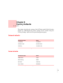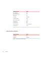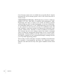
1
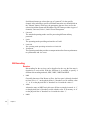
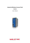
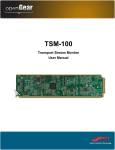
User’s Manual:
NETmate
NM-9010
Synchronous to Asynchronous Communication Interface
Software Revision 1.010
Copyright ©2004, ADD-Engineering B.V.
Copyright ©2004, ADD-Engineering B.V.
Online version copyright © 2004
All rights reserved.
Printed in the Netherlands
This document is protected by Copyright Protection Laws. The online
version of this document may be freely printed and distributed internally,
but cannot be modified, in whole or in part, or included in any other work
without prior written consent from ADD-Engineering B.V.
Limitation of Liability
ADD-Engineering B.V. makes NO WARRANTY, EXPRESSED or
IMPLIED, with respect to this user-manual, and any related items, its
quality, performance, merchantability, or fitness for any particular use. It is
solely the purchaser’s responsibility to determine its suitability for any
particular use. Information contained in this document is subject to change
without notice.
Trademark credits
The following are trademarks of ADD-Engineering B.V.
NETmate
SyncMate
ClockMate
Contents
••••••
Chapter 1
Chapter 2
Introduction
5
Functional Description
Specification Overview
Front and back panel
Front panel
11
PWR-LED
11
CH1-group
12
RxD
12
TxD
12
CTS
12
RxC
12
TxC
12
ExC
13
CH2-group
13
RxD
13
TxD
13
CTS
13
RxC
13
TxC
13
ExC
13
N-group
14
RxD
14
TxD
14
DRP
14
Back panel
14
6
7
11
•
•
• 1
•
•
•
Uplink
14
Led indicators
1
15
2
15
3
15
4
15
5
16
2
•
•
• Contents
•
•
•
15
Chapter 3
User Interface
17
Network
17
Authentication
18
Main menu
20
Chapter 4
Channel Setup
21
Channel Configuration 1
21
Bit Encoding
22
Bit Order
24
Sync Pattern
25
Sync Stripping
25
Bit Stuffing/Insertion
26
Frame-Size
27
Idle-State
27
Checksum-Mode
28
Synchronous Speed
28
Clock-source
30
Clock Line Inversion
31
Forward Data To
31
Async-Speed
31
Channel Configuration 2
33
Chapter 5
Network Configuration
35
IP-Configuration
35
MAC-Address
35
IP-Address
36
Netmask
36
Gateway
36
Save all
36
Chapter 6
Statistics Overview
37
Channel-1 Statistics
37
Serial Statistics
38
Frames Received
38
Bytes Received
38
Idles Received
38
Checksum/CRC Errors
38
Frames Transmitted
38
Bytes Transmitted
38
Idles Transmitted
38
Transmit Underruns
39
Network Statistics
39
Packets Received
39
Packets Ignored
39
Packets Transmitted
39
Packets Overflow
39
General
39
Reset
39
Channel-2 Statistics
40
Chapter 7
System Management
41
User Management
41
Old Username
42
New Username
42
Old Password
42
New Password
42
Retype New Password
Save all
42
Factory Settings
42
Reset
42
42
Contents
•
•
• 3
•
•
•
Firmware Upgrade
Upgrade
43
Chapter 8
4
43
Factory Defaults
45
Network defaults
45
Serial defaults
45
Authentication defaults
Appendix A
Warranty and Maintenance
Appendix B
Cables and Connectors
•
•
• Contents
•
•
•
46
47
51
Chapter 1
Introduction
••••••
Congratulations on purchasing your NETmate (NM-9010) from
ADD-Engineering. The NETmate combines dedicated communication
hardware with on-board data processing software to provide an efficient
means of interfacing asynchronous Data Terminal Equipment to
synchronous Data Communication Equipment.
By doing this the NETmate off-load communications overhead from your
Data Terminal Equipment’s CPU for optimum system performance.
•
•
• 5
•
•
•
Functional Description
The NETmate is a device that establishes the interface from standard
asynchronous serial ports with an RS-232 electrical interface (the ones
which are usually standard on computer systems) to standard as well as
"non-standard" synchronous systems with an RS-232 electrical interface
(non-standard in terms of Commercially Of The Shelf equipment).
The NETmate can interface a single synchronous system to a single
asynchronous system. Apart from the configurable "Universal-mode", the
NETmate also provides a Link-1, a Link-11B and a transparent interface
mode.
To provide flexibility and create a wide adaptation level within these
different modes, the NETmate has a number of parameters that can be
altered to be able to interface to specific military and commercial protocols.
Synchronisation word, bit encoding and bit stripping are only a couple of
these parameters.
Though the NETmate is designed from a total new concept, a lot of its
functionality is comparable to that of the standard UCC, SyncMate and the
ClockMate.
The NETmate provides more functionality, flexibility, stability,
configurability, ease of installation and fault check mechanisms.
Above all that, the NETmate also provides a mechanism to remote
monitor/configure the unit by means of a web-browser and a TCPI/IP based
ethernet connection.
System configuration security (and access control) is guaranteed by a username and password combination.
6
•
•
•
•
•
•
Chapter 1
Specification Overview
DCE / Asynchronous Interface
Ports
1
Connector
RJ-45 (socket)
Electrical Interface
RS-232
Speed
1200, 2400, 4800, 9600, 19k2 , 38k4,
115k2 bps
Start/Stop bits
1
Data bits
8
Bit order
LSB-first, MSB-first
Flow control
CTS/RTS
Input buffer
128 bytes
Output buffer
32 bytes
Available signals
CTS, RTS, TxD, RxD
Table 1: Specification of DCE interface
DTE / Synchronous Interface
Ports
1
Connector
RJ-45 (socket)
Electrical Interface
RS-232
Speed
600, 1200, 2400, 4800, 9600, 19k2, 56k,
64k bps
Clock mode
Internal, Dpll, External
Clock source
input: TxC, RxC
output: ExC
Sync Length
5...16 bits
Table 2: Specification of DTE interface
Introduction
•
•
• 7
•
•
•
DTE / Synchronous Interface
Frame Length
1..254 bytes
BIt Encoding
NRZ, !NRZ, NRZI, !NRZI
Sync Stripping/Insertion
On/Off
Bit Stripping/ Insertion
On/Off
Checksum Generation
Off/Xor/Xnor
Idle State
1, 0, Alternating
Clock Inversion
On/Off
Available signals
TxD, RxD, TxC, RxC, ExC,RTS,CTS
Table 2: Specification of DTE interface
Control Port / Ethernet
Ports
1
Connector
RJ-45 (socket)
Electrical Interface
Ethernet 100Mb/10Mb
Table 3: Specification of control port interface
Power Requirements
DC Input
7.5V / 1000mA
(through supplied 230V AC-adaptor)
Net Frequency
47 Hz - 63 Hz
Power Consumption
16 Watt
Table 4: Power requirements
8
•
•
•
•
•
•
Chapter 1
Dimensions
Enclosure
Metal painted light grey
Width
100 mm
Height
26 mm
Depth
79 mm
Table 5: Dimensions
Introduction
•
•
• 9
•
•
•
•
•
10 ••
•
•
Chapter 1
Chapter 2
Front and back panel
••••••
The NETmate is controlled and configured through a web-browser
interface. Through the use of this concept there is no requirement for a front
panel keyboard or configuration switches. Only the power supply connector
and indication LEDs are placed at the front panel of the unit.
Figure 1: NETmate front panel
Front panel
The front panel of the NETmate contains a large number of status LEDs (see
Figure 1: “NETmate front panel.”), each providing information on unit’s
status or an RS-232 signal. The large number of LEDs facilitates easy
troubleshooting of a configuration or connection.
PWR-LED
The PWR-LED indicates that power is supplied to the NETmate. If the
PWR-LED is on, power is supplied through the power supply connector, if
the PWR-LED is off, power is not supplied. When using another powersupply adapter than the one included, please make sure that the polarity is
correct.
•
•
• 11
•
•
•
CH1-group
The CH1-group provides information on the synchronous interface side of
the NETmate.
RxD
The RxD-LED indicates that reception of a frame is in progress.
TxD
The TxD-LED indicates that a transmission of a frame is in progress.
CTS
The CTS-LED indicates the state of the Clear To Send signal. In case the
CTS-LED is off, the NETmate will not transmit frames through the
synchronous interface. When the CTS state is inactive and the system
connected to the asynchronous side of the NETmate continues to provide
frames, the Clear To Send signal on the asynchronous side will change to
inactive (after the buffer is filled).
RxC
The RxC-LED indicates the state of the Receive Clock signal. The RxCLED is tied "directly" to the clock-signal on pin 17. A normal clock signal
alternates, the RxC-LED blinks at the same frequency as the clock signal.
TxC
The TxC-LED indicates the state of the Transmit Clock signal. The TxCLED is tied "directly" to the clock-signal on pin 15. A normal clock signal
alternates, the TxC-LED blinks at the same frequency as the clock signal.
•
•
12 ••
•
•
Chapter 2
ExC
The ExC-LED indicates the state of the External Clock signal. The ExCLED is tied directly to the clock-signal on pin 24. A normal clock signal
alternates, the ExC-LED blinks at the same frequency as the clock signal.
CH2-group
The CH2-group provides information on the asynchronous interface side of
the NETmate.
RxD
The RxD-LED indicates the reception of data from the asynchronous
interface side of the NETmate is in progress.
TxD
The TxD-LED indicates that the transmission of a frame just received (or in
progress) at the synchronous interface side, is in progress.
CTS
The CTS-LED indicates that the Clear To Send signal on the asynchronous
interface side is active, thus the system connected to the asynchronous
interface side is allowed to submit data.
RxC
The RxC-LED is not used by the NETmate model NM-9010.
TxC
The TxC-LED is not used by the NETmate model NM-9010.
ExC
The ExC-LED is not used by the NETmate model NM-9010.
Front and back panel
•
•
• 13
•
•
•
N-group
The N-group provides information on the network interface side of the
NETmate.
RxD
The RxD-LED is not used by the NETmate model NM-9010.
TxD
The TxD-LED is not used by the NETmate model NM-9010.
DRP
The DRP-LED is not used by the NETmate model NM-9010.
Back panel
The back panel of the NETmate (see Figure 2: “NETmate back panel.”)
contains 6 space saving RJ-45 connectors. Through the use of the supplied
RJ-45 to DB25 adapter cables, the unit can be connected to systems using a
DB25 physical interface.
Figure 2: NETmate back panel
Uplink
The Uplink-port is used to connect the NETmate to the 10/100Mb ethernet.
•
•
14 ••
•
•
Chapter 2
Led indicators
Left LED
Right LED
Color
Color
Meaning
Off
Off
No Link
Off
Solid Amber
100BASE-T Half Duplex Link
Off
Blinking Amber
100BASE-T Half Duplex Activity
Off
Solid Green
100BASE-T Full Duplex Link
Off
Blinking Green
100BASE-T Full Duplex Activity
Solid Amber
Off
10BASE-T Half Duplex Link
Blinking Amber
Off
10BASE-T Half Duplex Activity
Solid Green
Off
10BASE-T Full Duplex Link
Blinking Green
Off
10BASE-T Full Duplex Activity
Table 6: Network status LED indicators
1
Port number 1 is not used on the NETmate model NM-9010.
2
Port number 2 is not used on the NETmate model NM-9010.
3
Port number 3 is not used on the NETmate model NM-9010.
4
Port number 4 is the asynchronous interface of the NETmate. Use the cable
with the blue RJ-45 connector (and with the DB25-female connector)
supplied with the NETmate to connect to this port.
Front and back panel
•
•
• 15
•
•
•
5
Port number 5 is the synchronous interface of the NETmate. Use the cable
with the red RJ-45 connector (and with the DB25-male connector) supplied
with the NETmate to connect to this port.
•
•
16 ••
•
•
Chapter 2
Chapter 3
User Interface
••••••
The NETmate is equipped with an HTML-based user interface through an
embedded HTTP-server. Through the use of a standard HTTP-client (webbrowser) the unit can be configured in just a few minutes.
Network
The NETmate has the default settings as specified in Table 7: “Network
default settings.”.
Parameter name
Value
IP-address
192.168.1.1
Network mask
255.255.255.0
Default gateway
192.168.1.254
Table 7: Network default settings
To be able to configure the unit please make sure that the IP-address of the
system that is used to configure the NETmate, is within the network address
range of the NETmate. In other words, the configuring system should have
an address in the range 192.168.1.2 - 192.168.1.254.
•
•
• 17
•
•
•
Authentication
The first dialog that appears when trying to establish a conenction with the
NETmate is an authentication dialog see Figure 3: “Authentication dialog.”.
By entering the correct User Name and Password combination, access to the
NETmate is granted. The NETmate has the default settings for
authentication as specified in Table 8: “Authentication default settings.”
Parameter name
Value
User Name
root
Password
manager
Table 8: Authentication default settings
Figure 3: Authentication dialog
In case multiple attempt to logon fail or in case the "Cancel" button is
selected in the logon-dialog, the NETmate will generate a message "401
UNAUTHORIZED" that will be displayed in the web-browser as illustrated
in Figure 4: “Multiple logon attempts failed.”.
•
•
18 ••
•
•
Chapter 3
Figure 4: Multiple logon attempts failed
User Interface
•
•
• 19
•
•
•
Main menu
Using the HTML-links (underlined texts) provided on the Main menu (see
Figure 5: “Main menu.”), it is possible to navigate through the available
management, configuration and statistics menu’s of the NETmate.
Figure 5: Main menu
Please note the information in the top-right corner of the menu’s (in this case
the main menu).
Model Type
The specific model of the NETmate
Firmware Revision Revision of the software embedded in the NETmate
•
•
20 ••
•
•
Chapter 3
Serial Number
The factory assigned serial number
System Uptime
Elapsed time since the unit was powered on
Chapter 4
Channel Setup
••••••
The channel configuration menu can be selected by following the “Channel
Configuration 1” or “Channel Configuration 2” link from the Main menu.
Channel Configuration 1
After selecting the link the menu as illustrated in Figure 6: “Channel 1
Configuration.” is displayed.
Figure 6: Channel 1 Configuration
•
•
• 21
•
•
•
Serial data format type selects the type of “protocol” for the specific
channel. After selecting a specific serial data format the user should click on
the "Submit" button, in this way the parameters that are of no use for the
selected serial data format will be hidden. The NETmate provides 4 types of
channels, Universal, Link-1, Link-11B and Transparant.
•
Universal
The standard operating mode used for processing different military
protocols.
•
Link-1
The operating mode providing an interface to Link-1
•
•
Link-11B
The operating mode providing an interface to Link-11B
Transparent
The operating mode that provides a transparant interface from asynchronous
to synchronous and vice versa.
Bit Encoding
Receiver
Bit-encoding for the receiver can be described as the way the line-state is
decoded to a received bit. With the NETmate it is possible to specify 4
different bit-encoding methods, NRZ, !NRZ, !NRZI and NRZI.
•
NRZ
Generally known as Non Return to Zero, the line-state is directly decoded
to form a bit. A ‘1’ on the physical line is "decoded" to a bit with the value
‘1’. A ‘0’ on the physical line is "decoded" to a bit with the value ‘0’.
•
!NRZ
Almost the same as NRZ but in this case all bits are simply inverted. A ‘1’
on the physical line is "decoded" to a bit with the value ‘0’ in memory. A ‘0’
on the physical line is "decoded" to a bit with the value ‘1’.
•
•
•
22 ••
•
•
Chapter 4
NRZI
Generally known as Non Return to Zero Inverted. Although the name
implies that it is just the inverted version of NRZ, there is a more significant
difference between these two. To decode the line-state to a bit in NRZI
requires knowledge of the previous line-state. If there is a difference
between the previous line-state and the actual line-state then it is decoded to
a bit with the value ‘0’. If there is no difference between the previous and
the actual line-state then it is decoded to a bit with the value ‘1’. In short,
transitions will be decoded to form a bit with the value ‘0’ and steady states
will be decoded to form a bit with the value ‘1’.
•
!NRZI
Almost the same as NRZI but in this case all bits are simply inverted.
Transitions will be decoded to form a bit with the value ‘1’ and steady states
will be decoded to form a bit with the value ‘0’.
Transmitter
Bit-encoding for the transmitter can be described as the way the bits which
need to be transmitted are encoded to a line state.
•
NRZ
Generally known as Non Return to Zero, the bit is directly encoded to form
a line-state. A bit with the value ‘1’ is encoded to the physical line-state 1.
A bit with the value ‘0’ is encoded to the physical line-state ‘0’.
•
!NRZ
Almost the same as NRZ but in this case all bits are simply inverted first. A
bit with the value ‘1’ is encoded to the physical line-state ‘0’. A bit with the
value ‘0’ is encoded to the physical line-state ‘1’.
•
NRZI
To encode the bit to transmit to a line-state in NRZI requires knowledge of
the previous line-state. If a bit with the value ‘0’ needs to be encoded then
the line-state should alter, so the actual line-state should be the inverted
version of the previous line-state. If a bit with the value ‘1’ needs to be
encoded the actual line-state should be the same as the previous line-state.
In short, bits with the value ‘0’ will be encoded as transitions and bits with
the value ‘1’ will be encoded as steady-states.
•
!NRZI
Channel Setup
•
•
• 23
•
•
•
Almost the same as NRZI but in this case all bits are simply inverted first.
In short, bits with the value ‘1’ will be encoded as transitions and bits with
the value ‘0’ will be encoded as steady-states.
Bit Order
Receiver
For the receiver the bit-order can best be described as the order in which the
synchronously received bits are submitted to the asynchronous receiver. The
most commonly used bit-order is LSB-first, however some applications
require the opposite.
•
LSB-FIRST
The bit which is received first at the synchronous line will be placed at the
LSB-position of the byte which will be submitted to the asynchronous
receiver. No bit-reversal is taking place.
•
MSB-FIRST
The bit which is received first at the synchronous line will be placed at the
MSB-position of the byte which will be submitted to the asynchronous
receiver. In short it means that bit 0 becomes bit 7, bit 1 becomes bit 6 and
so on.
Transmitter
For the transmitter the bit-order can best be described as the order in which
the asynchronously received bytes are transmitted by the synchronous
transmitter. The most commonly used bit-order is LSB-first, however some
applications require the opposite.
•
LSB-FIRST
The bit at the LSB-position of the byte received at the asynchronous input
will be transmitted first by the synchronous transmitter. No bit-reversal is
taking place.
•
MSB-FIRST
The bit at the MSB-position of the byte received at the asynchronous input
will be transmitted first by the synchronous transmitter. In short it means
that bit 0 becomes bit 7, bit 1 becomes bit 6 and so on.
•
•
24 ••
•
•
Chapter 4
Sync Pattern
Receiver
The Sync-Pattern specifies the sync-word (a pattern of ones and zeros) on
which the receiver will synchronise. The length of the sync-pattern is a
minimum of 5 bits and a maximum of 16 bits. The sync-pattern is compared
after bit-decoding takes place. When the Sync-Pattern has been received the
device is considered to be in-sync. Bytes will now be submitted to the user
asynchronously.
Transmitter
The Sync-Pattern denotes the start of a frame. The pattern will be
transmitted if there are bytes in the internal buffer. If there are less bytes in
the buffer than the specified frame-length, the NETmate will transmit the
bytes in the buffer and fill up the remaining bytes (which were not
submitted) with idle bits. The Sync-Pattern is fully user definable.
Sync Stripping
To provide the user with the possibility to strip or not strip the sync-word
from the synchronously received data or to insert or not insert the sync-word
into the synchronously transmitted data, this option is implemented in the
NETmate.
Receiver
•
NOSTRIP
The synchronously received sync-word is submitted to the user via the
asynchronous output. In case the bit-order is reversed the sync-word will
also be reversed.
•
STRIP
The number of synchronisation bits are stripped from the synchronously
received data. In other words the sync-word is stripped from the data.
Transmitter
•
NOSTRIP
Nostrip in this context actually means no-insertion. No insertion of a syncword takes place at the synchronous transmitter side. The user has to submit
the sync-word via the asynchronous input port.
Channel Setup
•
•
• 25
•
•
•
•
STRIP
Strip means that the sync-word is inserted by the NETmate in case a new
frame needs to be transmitted. The sync-word that is inserted is specified by
the pattern "Sync-Pattern". The pattern should be read from right to left with
the right bit (LSB) transmitted first.
Bit Stuffing/Insertion
Specific bits are stripped from the data at the receiver's side and inserted at
the transmitter's side.
Receiver
At the receiver's side (synchronous) the specified bit will be stripped from
the data. The insert parameter in this menu is of no significance for the
receiver's side. The bitposition parameter specifies which bit will be
stripped after reception of the Sync-Word. Assuming the Sync-Word is
found and the strip/insert parameter is set to bitposition ‘1’, insert ‘0’. Then
the first bit after the Sync-Word is stripped from the data (in case SyncStripping is also enabled), then the next 8 bits are forwarded to the
asynchronous port and the next "first" bit is stripped from the data. This
continues until all the bytes of the frame are received.
Transmitter
At the transmitter's side (synchronous) the specified bit will be inserted in
the data. The insert parameter in this menu specifies if a ‘0’ or a ‘1’ will be
inserted. Assuming the Sync-Word has already been transmitted (and syncstripping is also enabled) and the strip/insert parameter is set to bitposition
‘1’, insert ‘0’. Then the first bit transmitted after the sync-word will be a ‘0’.
After that a byte which is submitted via the asynchronous port will be
forwarded to the synchronous port and then another ‘0’ will be inserted.
This continues until all the bytes of the frame are transmitted.
•
•
26 ••
•
•
Chapter 4
Frame-Size
The frame-size is selectable in the range of [1..254]. In general the FrameSize is the number of bytes the user will submit or can expect
asynchronously. The latter with some exceptions which can be read
hereunder.
Receiver
With the Fame-Length parameter the number of bytes which the user
expects is specified. The number of bytes are submitted to the asynchronous
side. All the bytes which are received are included in the Frame-Size. So, in
case the sync-word is not stripped the Sync-Word will count as part of the
total Frame-Length.
Transmitter
With the Frame-Length parameter the number of bytes which the user will
submit is specified. In case the Sync-Word is not stripped, the Sync-Word
should be submitted by the user via the asynchronous port and thus will
count as part of the Frame-Size. However, if a checksum-mode is selected,
one byte less should be submitted while the NETmate is generating its own
checksum to be forwarded with the data.
Idle-State
The idle-state is used to specify the behaviour of the transmitter in the case
that there are no bytes to transmit. The idle-state is directly related to the
line-state and thus no bit-encoding will take place. There are three possible
idle-states, ‘0’, ‘1’ and ALT.
Receiver
This parameter is of no significance for the receiver.
Transmitter
•
‘0’
Idle in zero's, invalid for NRZI and !NRZI bit encoding methods.
•
‘1’
Idle in one's, invalid for NRZI and !NRZI bit encoding methods.
•
ALT
Channel Setup
•
•
• 27
•
•
•
Idle in alternating states, normally this is used to keep receivers with DPLL
in sync.
Checksum-Mode
Checksums can be generated by the NETmate, it means that the user does
not have to calculate checksums over the data submitted to the NETmate.
The checksum is transmitted as the last byte of a frame. The checksummode has three options, OFF, XOR and XNOR.
Receiver
The checksum-mode parameter is of no significance in the receiver.
Transmitter
The checksum calculated using the method defined above is attached to the
frame as a last byte.
•
OFF
No checksum is attached to the frame
•
XOR
An XOR (exclusive or) will be performed over all the bytes in the frame
(except the sync-word).
•
XNOR
An XNOR (inverted exclusive or) will be performed over all the bytes in the
frame (except the sync-word).
Synchronous Speed
The Synchronous-Speed parameter of the NETmate has only significance if
INT (internal) or DPLL (digital phase locked loop) is enabled. In other cases
the transmit/receive clock submitted will dictate the synchronous speed.
Thus, when using external clock, the user is not limited by the selection of
synchronous-speeds down here. However, there is an upper-limit to the
external supplied synchronous clock which is 64k.
•
600
Data is clocked in and out at 600 bps.
•
•
•
28 ••
•
•
Chapter 4
1200
Data is clocked in and out at 1200 bps.
•
2400
Data is clocked in and out at 2400 bps.
•
4800
Data is clocked in and out at 4800 bps.
•
9600
Data is clocked in and out at 9600 bps.
•
19200
Data is clocked in and out at 19200 bps.
•
56K
Data is clocked in and out at 56kbps.
•
64K
Data is clocked in and out at 64 kbps.
Receiver
Data is clocked in at the selected speed.
Transmitter
Data is clocked out at the selected speed.
Channel Setup
•
•
• 29
•
•
•
Clock-source
With the NETmate it is possible to select three different clock-sources. The
first most commonly used is the external (EXT) clock-mode, the second is
the internal (INT) clock-mode and the third and last is the digital pll (DPLL)
clock-mode.
•
INT
The internal clock-mode is used when the NETmate should generate the
clocking signals required. The synchronous clock-speed can be selected
from the Sync-Speed menu. The clock which is generated internally is
placed on pin 24 of the DB25M connector.
•
DPLL
The digital pll clock-mode is used when synchronous data is coming in at a
known synchronous bit-rate but not accompanied by a clock signal. The
synchronous clock-speed can be selected from the Synchronous-Speed
menu. The clock which is generated internally is placed on pin 24 of the
DB25M connector. The internally generated clock is synchronised
continuously with the received data, or better with the transitions in this
data.
•
EXT
With the external clock-mode clock-signals should be connected to the
NETmate at pin 17 (RCLK) and pin 15 (TCLK). The RCLK is timebase
related to the data on pins 3 (RxD) and the TCLK is timebase related to the
data on pin 2 (TxD). The TCLK and RCLK need not to be related, however
usually they are.
Receiver
Data is clocked in at the rate specified by the clock-signal.
Transmitter
Data is clocked out at the rate specified by the clock-signal.
•
•
30 ••
•
•
Chapter 4
Clock Line Inversion
The NETmate has the capability to invert the clock signals when required
by the specific type of modem connected to the NETmate. The term
"inverted" means the opposite of the standard clock signal used for
commercial equipment. Clock Line Inversion OFF thus means that the
NETmate is adapted for commercial synchronous equipment.
•
ON
The clock signals (incoming and outgoing, TxC, RxC, ExC) of the
NETmate are inverted.
•
OFF
The clock signals (incoming and outgoing, TxC, RxC, ExC) of the
NETmate are not inverted.
Receiver
Data is clocked in at the inverted or non-inverted clock-signal.
Transmitter
Data is clocked out at the inverted or non-inverted clock-signal.
Forward Data To
The NETmate model NM-9010 can only forward data to the asynchronous
channel 2 (Async-Channel-2).
Async-Speed
The speed selected in this menu is used to transmit and receive
asynchronous data via the asynchronous ports. Make sure that the
asynchronous baudrate is always higher than the synchronous speed.
•
1200
Asynchronous bitrate is 1200, No Parity, 8 Bits, 1 Stop bit.
•
2400
Asynchronous bitrate is 2400, No Parity, 8 Bits, 1 Stop bit.
•
4800
Channel Setup
•
•
• 31
•
•
•
Asynchronous bitrate is 4800, No Parity, 8 Bits, 1 Stop bit.
•
9600
Asynchronous bitrate is 9600, No Parity, 8 Bits, 1 Stop bit.
•
19200
Asynchronous bitrate is 19200, No Parity, 8 Bits, 1 Stop bit.
•
38400
Asynchronous bitrate is 38400, No Parity, 8 Bits, 1 Stop bit.
•
115K2
Asynchronous bitrate is 115200, No Parity, 8 Bits, 1 Stop bit.
Receiver
The asynchronous receive rate.
Transmitter
The asynchronous transmit rate.
•
•
32 ••
•
•
Chapter 4
Channel Configuration 2
After selecting the link the menu as illustrated in Figure 7: “Channel 2
Configuration.” is displayed
Figure 7: Channel 2 Configuration
The NETmate model NM-9010 only supports 1 synchronous
communication channel, thus channel-2 can not be configured.
Channel Setup
•
•
• 33
•
•
•
•
•
34 ••
•
•
Chapter 4
Chapter 5
Network Configuration
••••••
The NETmate has a number of network parameters that can be configured
to adapt the NETmate to your Local Area Network configuration. After
selecting the IP-Configuration link, the following menu is displayed.
IP-Configuration
Figure 8: IP-Configuration menu
MAC-Address
The MAC-Address specifies the unique hardware address of the NETmate.
The hardware address can not be altered and is only displayed in this menu
for information.
•
•
• 35
•
•
•
IP-Address
The IP-address of the NETmate. The user should take care that a network
unique IP-address is assigned to the NETmate.
Netmask
The network mask of the NETmate and in this way selects a class-A, classB or a class-C network. Please see other documentation on TCP/IP for a
detailed explanation on the netmask.
Gateway
The gateway to use when communicating with systems outside the Local
Area Network.
Save all
After making the required changes, click on the "Save all" button to store
the settings in the NETmate. After storing these settings, the NETmate will
reboot. Please follow instructions as displayed in Figure 9: “IPConfiguration menu.”.
Figure 9: IP-Configuration menu
•
•
36 ••
•
•
Chapter 5
Chapter 6
Statistics Overview
••••••
The NETmate has a number of facilities to monitor the behaviour of the
communication link and the unit. By selecting "Channel-1 Statistics" or
"Channel-2 Statistics" information is provided on the selected synchronous
channel.
Channel-1 Statistics
After selecting the "Channel-1 Statistics" link, the menu as illustrated in
Figure 10: “Channel 1 Statistics menu.” is displayed.
Figure 10: Channel 1 Statistics menu
•
•
• 37
•
•
•
Serial Statistics
Frames Received
The number of frames received through the synchronous interface side.
Bytes Received
The number of bytes received through the synchronous interface side.
Idles Received
The number of idles (idle-bytes) received through the synchronous interface
side.
Checksum/CRC Errors
Only applicable to the Link-1 and Link-11B data format. Indicates the
number of detected checksum errors for the specified data format.
Frames Transmitted
The number of frames transmitted through the synchronous interface side.
Bytes Transmitted
The number of bytes transmitted trhough the synchronous interface side.
Idles Transmitted
The number of idles (idle bytes) transmitted through the synchronous
interface side.
•
•
38 ••
•
•
Chapter 6
Transmit Underruns
The number of transmitter underruns. An underrun occurs when the request
for data is not handled successfully. Normally this should remain 0.
Network Statistics
The network statistics are applicable to the data packets (thus the frames
received/transmitted through the synchronous interface) send/received
through the network interface. Since the NETmate model NM-9010 has no
capability to transfer synchronously received/transmitted data across the
network, the network statistics are not applicable.
Packets Received
Not applicable to the NETmate model NM-9010
Packets Ignored
Not applicable to the NETmate model NM-9010
Packets Transmitted
Not applicable to the NETmate model NM-9010
Packets Overflow
Not applicable to the NETmate model NM-9010
General
Reset
Sets all the statistics to the value of zero.
Statistics Overview
•
•
• 39
•
•
•
Channel-2 Statistics
After selecting the "Channel-2 Statistics" link the following menu is
displayed.
Figure 11: Channel 2 Statistics menu
Since the NETmate model NM-9010 only supports one synchronous
communication channel, channel-2 statistics are not available.
•
•
40 ••
•
•
Chapter 6
Chapter 7
System Management
••••••
Through system-management the firmware of the unit can be upgraded, the
unit’s settings can be reset to factory defaults and the username and
password combination can be changed.
User Management
When clicking on the link "User Management" the menu as illustrated in
Figure 12: “User Management menu.” is displayed. Through this menu, the
username and password can be changed. After changing username and
password, the same menu is displayed. When selecting another menu, an
authentication dialog (logon-dilalog) is displayed where the new username
and password should be entered.
Figure 12: User Management menu
•
•
• 41
•
•
•
Old Username
The current username
New Username
The new username (minimum of 5 characters)
Old Password
The current password
New Password
The new password
Retype New Password
The new password (for verification).
Save all
Saves the settings.
Factory Settings
When clicking on the link "Factory Settings" the following menu is
displayed. Through this menu, the factory defaults can be re-programmed
into the NETmate again. Please use http://192.168.1.1 to reconnect to the
NETmate after resetting to defaults.
Reset
Resets to default and reboots the unit.
•
•
42 ••
•
•
Chapter 7
Firmware Upgrade
When clicking on the link "Firmware Upgrade" the menu as illustrated in
Figure 13: “Firmware upgrade menu.” is displayed. Through this menu, the
firmware embbeded in the NETmate can be upgraded.
Figure 13: Firmware upgrade menu
Upgrade
Places the NETmate into "firmware upgrade mode". The unit is now ready
for a new software version. Please use the appropiate software upgrade tool
supplied by ADD-Engineering. Do not power off the unit when firmware
upgrade is in progress (and thus the upgrade tool has been started). The unit
should never be powered off when the upgrade tool has been started
and a firmware upgrade is in progress. The NETmate can be damaged
permanently when not following the instructions above.
System Management
•
•
• 43
•
•
•
•
•
44 ••
•
•
Chapter 7
Chapter 8
Factory Defaults
••••••
This chapter describes the settings of the NETmate model NM-9010 when
shipped by ADD-Engineering. These settings can be restored using the
"Factory Settings" option in the System Management group.
Network defaults
Parameter name
Value
IP-address
192.168.1.1
Network mask
255.255.255.0
Gateway
192.168.1.254
Table 9: Network default settings
Serial defaults
Parameter name
Value
Data format
Link-1
Bit Encoding
!NRZI
Bit Order
LSB-First
Sync Pattern
00000000
Table 10: Serial port default settings
•
•
• 45
•
•
•
Parameter name
Value
Sync Stripping
ON
Bit Stuffing/Insertion
00
Frame Size
16
Idle State
Alternate
Checksum-Mode
OFF
Synchronous Speed
1200
Clock-source
EXT
Clock-inversion
ON
Forward Data To
Async-Channel-2
Async Speed
2400
Table 10: Serial port default settings
Authentication defaults
Parameter name
Value
Username
root
Password
manager
Table 11: Authentication default settings
•
•
46 ••
•
•
Chapter 8
Appendix A
Warranty and Maintenance
••••••
Warranty Information
Hardware
All ADD-Engineering B.V.’s hardware products are covered by a one year
warranty from the original date of purchase. Warranty coverage includes:
Telephone support. Free phone support on any hardware product for one
year after initial product purchase. ADD-Engineering’s Customer Service
and Support (CSS) hours are 9:00 am to 5:00 pm, Monday through Friday.
Rapid replacement. Upon CSS phone verification of hardware failure
within the first 90 days after purchase, ADD-Engineering will issue a return
material authorization (RMA) number for rapid replacement. If the failed
unit is in stock, a replacement unit will be shipped within one business day.
If the failed unit is not in stock, it will receive the highest priority for repair
once ADD-Engineering receives the unit.
Extended maintenance option. Extends the standard warranty coverage,
including rapid replacement, to three years when purchased within 90 days
of initial product purchase.
•
•
• 47
•
•
•
Out of warranty repair service is available for a per-product flat fee. Typical
turnaround for out-of-warranty repairs is four to six weeks from date of
factory receipt.
Limited Hardware Warranty. ADD-Engineering warrants its hardware
products to be free from defect in materials and workmanship. ADDEngineering will repair or replace (at its option) all defective product
returned freight pre-paid, in original packaging, to its factory in Rotterdam,
The Netherlands within one (1) year. ADD-Engineering reserves the right
to ship replacement units from our inventory of reconditioned units. All
other warranties, expressed or implied, are limited to the restrictions of this
warranty. Product abuse, alteration, or misuse invalidates all warranties.
This warranty does not cover damages incurred by natural or electrical
forces exceeding the stated product specifications. In no event will ADDEngineering’s warranty liability exceed the purchase price of the product.
No liability is assumed for any consequential damages resulting from the
use of any ADD-Engineering product.
This warranty is in lieu of all other warranties, including but not limited to
the warranties of merchantability and fitness for a particular purpose.
National, state and local laws may offer rights in addition to those stated
above.
•
•
48 ••
•
•
Appendix A
Product Information Worksheet
Please record the following information about your NETmate
model NM-9010.
NETmate Serial number:
NETmate MAC address:
Purchase date:
Warranty and Maintenance
•
•
• 49
•
•
•
•
•
50 ••
•
•
Appendix A
Appendix B
Cables and Connectors
••••••
This appendix provides necessary background information for making
connections to the serial and the network ports on the NETmate model
NM-9010. It discusses modem and null modem connectors, the standard
RS-232 pinouts, the RJ-45 pinouts, and describes some typical cables
Two terms used frequently throughout this appendix are
• Data Communication Equipment (DCE)
• Data Terminal Equipment (DTE)
DCE peripheral devices usually refer to modems
DTE devices include terminals, computers and printers.
•
•
• 51
•
•
•
Cabling Overview
To connect a peripheral device to the NETmate, you need an interface cable
to run electrical signals from one of the RJ-45 connectors to the peripheral
device. ADD-Engineering includes the cables required to connect the
NETmate to a standard asynchronous port and to a standard synchronous
port. Cables required to connect the NETmate to the network are not
included. You can purchase ready-made network cables at your local
computer store or make them on your own
DCE and DTE devices send and receive signals through different pins. The
NETmate is at one side (asynchrounous) configured to be a DCE device
with an RS-232 electrical interface and on the other side (synchronous) to
be a DTE device with an RS-232 electrical interface.
•
•
52 ••
•
•
Appendix B
Serial Connector Pinouts
All of the NETmate’s synchronous communication ports are equipped with
an RJ-45 connector. The electrical interface for these ports is RS-232. The
port behaves like a DTE (with respect to the clocking signals).
1
8
Figure 14: Serial connector pin diagram (DTE RJ-45)
Pin Number
RS-232 Signal
V.24 Signal
Direction
1
RxC
115
Input
2
TxC
114
Input
3
ExC
113
Output
4
Signal GND
5
RxD
104
Input
6
TxD
103
Output
7
CTS
106
Input
8
RTS
105
Output
None
Table 12: Pinout of synchronous serial interface
Cables and Connectors
•
•
• 53
•
•
•
All of the NETmate’s asynchronous ports are equipped with an RJ-45
connector. The electrical interface for these ports is RS-232. The port
behaves like a DCE (with respect to the handshaking signals).
1
8
Figure 15: Serial connector pin diagram (DCE RJ-45)
Pin Number
RS-232 Signal
V.24 Signal
Direction
1
2
3
4
Signal GND
None
5
RxD
103
Input
6
TxD
104
Output
7
RTS
105
Input
8
CTS
106
Output
Table 13: Pinout of asynchronous serial interface
•
•
54 ••
•
•
Appendix B
Signal
Description
TxD
Transmit Data. Sends data to peripheral device
RxD
Receive Data. Receives data from the peripheral
RxC
Receive Data Clock. Input for receiver signal element timing
from a synchronous DCE-device.
TxC
Transmit Data Clock. Input for transmitter signal element
timing from a synchronous DCE-device
TxC
Transmit Data Clock. Output for transmitter signal element
timing generated on the NETmate
CTS
Clear To Send handshake signal
RTS
Request To Send handshake signal
Table 14: Signal descriptions
RJ-45 to DB25-male cable (RED)
RJ-45 Pin Number RS-232 Signal
Direction
DB25-male Pin Number
1
RxC
<-
17
2
TxC
<-
15
3
ExC
->
24
4
Signal GND
5
RxD
<-
3
6
TxD
->
2
7
CTS
<-
5
8
RTS
->
4
7
Table 15: RJ-45 to DB25-male cable pinout
Cables and Connectors
•
•
• 55
•
•
•
RJ-45 to DB25-female cable (BLUE)
RJ-45 Pin Number RS-232 Signal
Direction
DB25-female Pin Number
1
2
3
4
Signal GND
5
RxD
<-
2
6
TxD
->
3
7
RTS
<-
4
8
CTS
->
5
Table 16: RJ-45 to DB25-female cable pinout
•
•
56 ••
•
•
Appendix B
7
Numerics
401 UNAUTHORIZED 18
A
alternating 28
Asynchronous Interface 7
asynchronous ports 54
Async-Speed 31
Authentication 18
Authentication defaults 46
B
back panel 14
Bit Stuffing/Insertion 26
Bit-encoding 22
bit-order 24
C
Cabling Overview 52
CD-2 6, 22
CH1-group 12
CH2-group 13
Channel Configuration 1 21
Channel Configuration 2 33
Channel Setup 21
Channel-1 Statistics 37
Channel-2 Statistics 40
Checksum-Mode 28
Clock Line Inversion 31
ClockMate 6
clock-sources 30
Control Port 8
D
digital pll clock 30
Dimensions 9
DPLL 30
E
EXT 30
external clock 30
F
Factory Settings 42
•
•
• 57
•
•
•
Firmware Upgrade 43
Forward Data To 31
frame-length 27
front panel 11
Functional Description 6
G
Gateway 36
H
HTTP-server 17
I
idle-state 27
INT 30
internal clock 30
IP-Address 36
IP-Configuration 35
L
Led indicators 15
Link-11B 22
LSB-FIRST 24
M
MAC-Address 35
Main menu 20
MSB-FIRST 24
N
Netmask 36
Network 17
Network defaults 45
Network Statistics 39
N-group 14
NRZ 22
NRZI 22
P
pinouts 51
Power Requirements 8
PWR-LED 11
S
Serial defaults 45
Serial Statistics 38
•
•
58 ••
•
•
strip 25
Synchronous Interface 7
SyncMate 6
Sync-Pattern 25
Sync-Speed 28
system-management 41
T
Transparent 22
transparent 6
U
UCC 6
Universal 6, 22
user interface 17
User Management 41
W
Warranty Information 47
X
XNOR 28
XOR 28
•
•
• 59
•
•
•