1
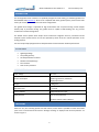
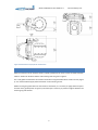
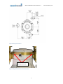
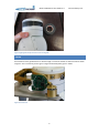
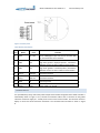
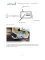
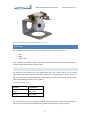
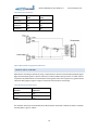
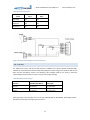
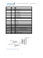
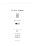
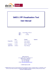
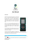
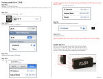
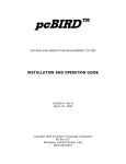
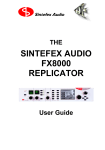
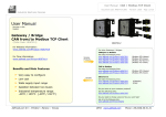
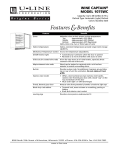
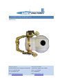
GR-01 GIMBAL RETRACT USER GUIDE V1.0 March 25, 2013 UAV Factory USA LLC. UAV Factory LTD. EUROPE 50 South Buckhout Street, Irvington, NY 10533 USA 7 Peldu Street, Jelgava, Latvia, LV3002 Phone: +1 (914) 591 3296 Phone: +371 9119398 Fax: +1 (914) 591 3715 Fax: +37163048747 Email: [email protected] Email: [email protected] GR-01 Gimbal Retract User Guide v1.0 www.uavfactory.com CONTENTS Introduction .................................................................................................................................................... 3 Key features ............................................................................................................................................... 3 Specifications ............................................................................................................................................. 3 Dimensions ..................................................................................................................................................... 3 Mounting ........................................................................................................................................................ 4 Wiring ............................................................................................................................................................. 6 QUICK SETUP KIT ........................................................................................................................................ 7 OPERATION ..................................................................................................................................................... 9 PWM control .............................................................................................................................................. 9 Discrete input control .............................................................................................................................. 10 CAN control .............................................................................................................................................. 11 Version history.............................................................................................................................................. 13 2 GR-01 Gimbal Retract User Guide v1.0 www.uavfactory.com INTRODUCTION The GR-01 gimbal retract mechanism is specifically designed for OTUS U135 gyro-stabilized gimbals from DST CONTROL AB (www.dst.se). GR-01 is not compatible with other gimbal systems- please contact UAV Factory for custom gimbal retraction mechanism configurations. The gimbal retract design is optimized for high accelerations that are present during aircraft catapult takeoff, belly or parachute landing. The gimbal retract is capable of withstanding over 20 g vertical acceleration in stowed configuration. The flexible control options allow simple retract mechanism integration with any unmanned aircraft autopilot system. Gimbal retract can be also operated by switch circuit for manned operations or lab testing purposes. Unit can be optionally equipped with air-damped isolators for best vibration isolation performance. KEY FEATURES Lightweight design Low profile geometry Air-damped vibration isolators Durable and simple design Fast retraction Over-current protection SPECIFICATIONS Input Voltage 10 - 14 V Power consumption 7W during actuation, 0.6W when deployed/retracted Weight < 450 grams Retraction time < 1 second Control method CAN/PWM/ discrete input Safety features Over-current protection Up/down position status indication DIMENSIONS GR-01 has very low mounting profile and small volume, which makes it possible to install into limited space such as unmanned aircraft vehicle’s fuselage. Drawings in deployed and retracted positions are shown in Figure 1. 3 GR-01 Gimbal Retract User Guide v1.0 www.uavfactory.com Figure 1 GR-01 dimensions in deployed and retracted states. MOUNTING GR-01 is mounted on three vibration isolators, equally spaced from the center of mass for better vibration isolation. Position of vibration isolators and mounting holes are given in Figure 2. The U-135 gimbal is fastened to the retraction mechanism using three M4x 16mm machine screws (Figure 3). It is recommended to apply soft thread locker on the mounting screws. Before inserting the gimbal base into the retraction mechanism, it is necessary to apply electrical tape to the base of the gimbal (shown in Figure 4). Electrical tape is necessary to produce a tight fit between the mounting ring and the base. 4 GR-01 Gimbal Retract User Guide v1.0 Figure 2 Mounting hole dimensions 3x M4 16 mm screws Figure 3 U-135 gimbal and retraction mechanism interface 5 www.uavfactory.com GR-01 Gimbal Retract User Guide v1.0 www.uavfactory.com Figure 4 Applying electrical tape to the base of the U-135 gimbal WIRING All connections to the gimbal retract are done through J1 connector located on electronics PCB as shown in Figure 5. The J1 connector pinout is given in Figure 6 with descriptions given in Table 1 Figure 5 Electronics PCB 6 GR-01 Gimbal Retract User Guide v1.0 www.uavfactory.com Figure 6 J1 connector pinout Table 1 GR-01 J1 pin descriptions Pin Name Level Function 1 CCP1 TTL input Servo PWM/Digital input with internal 10 kOhm pullup, with automatic source selection 2 LED2 +5V High when gimbal in deployed position , with built-in 330 Ohm resistor for direct indication led connection 3 LED1 +5V High when gimbal in retracted position, with built-in 330 Ohm resistor for direct indication led connection 4 CAN_H CAN High CAN communication 5 CAN_L CAN Low CAN communication 6 GND 0V Common ground 7 Power +12V Power supply 10 - 14 VDC QUICK SETUP KIT For quick laboratory setup, UAV Factory offers simple hand controller and gimbal stand. Hand controller is schematically shown in Figure 7. First, connect the controller cable to the J1 connector on the gimbal retraction mechanism. Apply 10 - 14 VDC power source to the hand controller. Use retraction switch to deploy or retract the GR-01 retraction mechanism. The connected hand controller is shown in Figure 8 7 GR-01 Gimbal Retract User Guide v1.0 www.uavfactory.com Retraction switch 10-14 VDC power input Status indication LEDs Figure 7 GR-01 hand controller Figure 8 hand controller connected to retraction mechanism The Otus U-135 gimbal and retraction mechanism assembly can be conveniently mounted on aluminum stand which is supplied with the Quick Setup Kit. The stand offers simple access to retract mechanism and U-135 gimbal’s electrical connections. 8 GR-01 Gimbal Retract User Guide v1.0 www.uavfactory.com Figure 9 Retraction mechanism with U-135 gimbal on aluminum stand OPERATION Three possible control methods can be used for gimbal retraction mechanism operation: CAN PWM Discrete input GR-01 automatically recognizes input signal. Status indication can be seen through CAN messages or indication LEDs located on GR-01 electronics PCB. PWM CONTROL The GR-01 can be operated with servo PWM signal input. This control method can be quickly implemented with most autopilot system. Wiring diagram for connecting GR-01 is given in Figure 10. Signal can be given by autopilot PWM output. If control signal is lost, GR-01 will be commanded to retract. Commanding PWM signal width is given in Table 2. Table 2 PWM control commands Function Pulse width, µs Deploy 900 – 1450 Retract 1550 – 2100 The indication led can be connected directly to GR-01 because of the built in internal 330 Ohm resistors to reduce external components and facilitate setup. Indication LED description is given in Table 3. 9 GR-01 Gimbal Retract User Guide v1.0 www.uavfactory.com Table 3 GR-01 status indication led Status LED 1 LED 2 Retracted ON OFF Deployed OFF ON Undefined OFF OFF Figure 10 Recommended wiring diagram for PWM control DISCRETE INPUT CONTROL GR-01 allows controlling its position by using a simple switch or discrete microcontroller/autopilot signal. Signal level description given in Table 4. Control pin has built 10 kOhm pull-up resistor to reduce external components. By default GR-01 is commanded to retract gimbal and if loss of signal occurs, gimbal will be retracted. Wiring diagram is given in Figure 11. Discrete control function uses 5V logic. Table 4 Discrete input commands on CCP1 Function Input level Retract High Deploy Low The indication led can be connected directly to GR-01 because of the built in 330 Ohm resistors. Indication LED description is given in Table 5. 10 GR-01 Gimbal Retract User Guide v1.0 www.uavfactory.com Table 5 GR-01 status indication led Status LED 1 LED 2 Retracted ON OFF Deployed OFF ON Undefined OFF OFF Figure 11 Recommended wiring diagram for discrete input control CAN CONTROL The GR-01 uses version 2.0B of the CAN protocol at 1Mbaud. This version specifies extended 29bit identifier for each CAN frame. Recommended wiring diagram is shown in Figure 12. GR-01 has built in 120 Ohm CAN line terminating resistor. The following CAN messages (Table 6) are used to command retract/deploy. No parameters are used. It may be a zero length message. Table 6 GR-01 CAN command messages Function CAN Message HEX ID Data length Retract 0x1203xxxx any (0-8) bytes Deploy 0x1202xxxx any (0-8) bytes GR-01 generates status message sent at 10 Hz rate. Message HEX ID: 0x12010001, data length: 8 bytes. Description of CAN status message is given in Table 7. 11 GR-01 Gimbal Retract User Guide v1.0 Table 7 GR-01 CAN status message Byte Value 0 Name Detected stop, uint8 0 NOT_DETECTED 1 FULLY_DEPLOYED 2 FULLY_RETRACTED 3 ERROR_DETECTED 1 Motor direction, uint8 0 OFF 1 DEPLOYING 2 RETRACTING 2 - Reserved 3 - Reserved 4 uint16 Motor current, uint16, LSByte, milliamps 5 uint16 Motor current, uint16, MSByte, milliamps 6 - Reserved 7 uint8 Message counter, uint8 Figure 12 Recommended wiring diagram for CAN control 12 www.uavfactory.com GR-01 Gimbal Retract User Guide v1.0 www.uavfactory.com VERSION HISTORY Version Comments, Updates Initial release of GR-01 user manual 1.0 13 Date 25.03.2013 Author GM