1
SAUTER flexotron®800
User program
Heating
User Guide
P100013121 A
P100013120
flexotron®800

2/36
P100013121 A
flexotron®800
Contents
Contents
1 About this user guide
1.1Disclaimer
1.2Trademark
1.3
Further information
5
5
5
5
2 About flexotron®8007
2.1
Heating control: Summary of functions
8
P100013121 A
3 Display, buttons and LEDs
3.1Display
3.2
Buttons and LEDs
13
13
14
4 The menu system
4.1
Menu navigation
4.1.1 Editing parameters
4.2
HS1..HS3, HW1..2, CS1, …
4.2.1Actual/setpoint
4.2.2 Temperature control
4.2.3Manual/auto
4.2.4 ECO/comfort function
4.3
Time / timer outputs
4.4Holiday
4.5
Energy/Cold water
4.6
Running mode
4.7
Access rights
15
15
16
17
17
20
21
23
23
24
25
27
28
5 Other functions
5.1
Alarm handling
5.2
Individual text field
5.3
Version number
5.4Language
5.5
Indicator LEDs
5.5.1 Status indicator
5.6
Changing the battery
5.7
Start assistant
5.8
Basic configuration for heating
31
31
32
32
32
33
33
33
34
34
3/36
flexotron®800
4/36
P100013121 A
flexotron®800
About this user guide
1
About this user guide
This user guide covers all the models in the flexotron®800 series used for heating
control.
The functions described here are for users with the Operator access level or
lower.
Revision A, March 2014
Software version: 3.2
1.1
Disclaimer
The information in this user guide has been carefully checked and judged to be
correct. Fr. Sauter AG makes no guarantee regarding the content of this manual
and requests the reader to report any errors, inaccuracies or unclear formulations
so that they can be corrected. The information in this document is subject to
change without notice.
No part of this document may be reproduced or passed on to third parties in any
form or fashion without the permission of Fr. Sauter AG.
1.2
Trademark
flexotron® is a registered trademark of Fr. Sauter AG.
Windows, Windows 2000, Windows XP and Windows Server 2003 are registered
trademarks of the Microsoft Corporation.
Some product names mentioned in this document are used for identification
purposes only and may be the registered trademarks of their respective companies.
1.3
Further information
More information on the flexotron®800 can be found in the following documents:
• flexotron®800 heating user manual – complete user manual for configuring
and operating the flexotron®800 heating controller, available in English, German
and French.
• CASE flexotron® user manual – user manual for configuring the controllers
using the CASE flexotron® PC software, available in English, German and
French.
• Network variables for Modbus – list of variables for Modbus communication,
available in English.
• CE declaration of conformity for flexotron®800
This information can be downloaded from http://www.sauter-controls.com/de.
P100013121 A
5/36
flexotron®800
About this user guide
6/36
P100013121 A
flexotron®800
About flexotron®800
2
About flexotron®800
The flexotron®800 devices comprise a series of pre-programmed, configurable
controllers for various applications.
The flexotron®800 series is available in three model sizes, with 8, 15 or 28 inputs/
outputs.
The controllers are available with or without a display and buttons. Units without
a display and buttons can be connected to an external display with buttons
(RDB800).
All the standard functions can be carried out using the display and buttons, or with
the CASE flexotron® configuration tool. CASE flexotron® is installed on a computer
and connected via a cable to the controller.
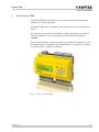
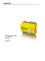
Fig. 1
P100013121 A
Picture of flexotron®800
7/36
flexotron®800
About flexotron®800
2.1
Heating control: Summary of functions
The controller has programs for heating, domestic hot water, cooling and boiler
control.
The temperature controller is based on PI controllers with pre-programmed control
functions. Various control functions and analogue and digital input and output
functions can be activated in this controller. Certain functions are mandatory, while
others can be selected as options. This means that the display varies according to
the model and the selected functions.
Changes to functions cannot be made with the Operator access level described in
this manual, but only by users with administrator rights. Also, this should only be
done by trained staff. The same goes for all other configurations.
The following functions are among those included in the heating control:
Heating control
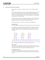
The flexotron®800 can be configured for 1-3 heating systems (HS1, HS2 and HS3).
The controllers have individual control characteristics for the relationship between
the supply temperature and the outside temperature. The heating systems have
individually adjustable minimum and maximum temperature limits for the supply
and return.
Fig. 2
Heating circuits with the maximum number of available elements
Pump control
Each circuit can be equipped with single or twin pumps. With twin pumps, only one
of the pumps is operated at a time. They automatically switch over once a week. If
the active pump fails, the inactive pump is automatically started up.
Frost-protection facility
If a controller is in Off or Manual mode and the outside temperature falls below a
set value, an adjustable minimum supply temperature is maintained and the pump
starts up.
8/36
P100013121 A
flexotron®800
About flexotron®800
Night reduction
The night reduction is set using the room temperature.
Cooling system
A cooling system can be configured using the controller. The setpoint for the
cooling system can be fixed or weather-dependent.
Fig. 3
Cooling circuit with the maximum number of available elements
Pump control
A digital output can be used in the cooling system to control the pump. The pump
can be configured either for continuous operation or with pump stops.
Temperature limiter
The supply temperature can be assigned a value as a fixed upper limit. It is also
possible to set upper and lower limits for the return temperature.
P100013121 A
9/36
flexotron®800
About flexotron®800
Domestic hot water
The flexotron®800 can be configured for either one or two domestic hot water
circuits, HW1 and HW2. These are regulated using a constant supply temperature.
Fig. 4
Domestic hot water with the available elements
The circulation pump of the first circuit can be controlled using a digital output
signal.
To prevent the risk of legionella bacteria, the anti-legionellae function for the first
circuit, HW1, can be activated.
10/36
P100013121 A
flexotron®800
About flexotron®800
Boiler control
The flexotron®800 can be configured to control up to 4 boilers. The burners for
each boiler can be set to 1-step, 2-step or modulating regulation, depending on the
type of boiler control.
The boiler control setpoint can be adjusted to a fixed value or according to the
heating/domestic hot water control loop.
To minimise the risk of condensation in the boiler, the return temperature can be
regulated.
Fig. 5
Boiler circuits with two of the maximum four available boilers.
Consumption measurements
Measurements and monitoring of cold water consumption, energy consumption,
leak monitoring and electricity meters can be configured using pulse inputs.
P100013121 A
11/36
flexotron®800
12/36
P100013121 A
flexotron®800
Display, buttons and LEDs
3
Display, buttons and LEDs
This section applies to flexotron®800 controllers with a display and buttons, as
well as the RDB800 external display. The external display can be connected to
flexotron®800 models without a display and buttons.
RDB800F001
3.1
Display
The display has four rows of 20 characters and is backlit. The lighting is normally
off. The lighting is activated when the buttons are pressed, and is switched off again
after a certain period with no activity.
Heating controller
2013-11-27 14:10
HS1
Sp: 52.0 Act: 52.5
P100013121 A
13/36
flexotron®800
Display, buttons and LEDs
3.2
Buttons and LEDs
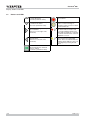
ARROW up (Up button):
Scroll up the menu.
(Increase parameter value)
Alarm:
List of alarms.
ARROW down (Down button):
Scroll down the menu.
(Decrease parameter value)
Correction:
Reset or cancel a change to
parameter values if it has not been
confirmed with OK.
ARROW right (Right button):
Open submenu.
(Set cursor to the right of the
parameter)
Alarm LED:
The alarm indicator flashes red
for unacknowledged alarms. The
alarm indicator lights up constantly
for alarms that have been acknowledged but not reset.
ARROW left (Left button):
Quit submenu.
(Set cursor to the left of the
parameter)
Input LED:
Some menus have adjustable
values. These are indicated by the
flashing yellow LED. The value can
be changed by pressing the OK
button.
OK:
Opens/activates the selected
menu or setting.
(Confirms a parameter value)
14/36
P100013121 A
flexotron®800
The menu system
4
The menu system
4.1
Menu navigation
Depending on the user/access level, the corresponding menu is displayed.
Heating controller
2013-11-27 14:10
HS1
Sp: 52.0 Act: 52.5
The start menu is on the basic level of the menu tree. The appearance of the start
menu depends on the settings in the configuration. The text in the first line can also
be changed with CASE flexotron®.
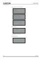
The abbreviations Sp and Act stand for the setpoint and actual value of the
controller.
Actual value = the currently measured temperature.
Setpoint = the desired/set temperature.
Press the Down button to go through the menus to the lowest level. Press the Up
button to go back up.
Depending on your access level, various menus are displayed (see the “Access
levels” section for more information on logging into a higher access level).
On the basic level, which is displayed without a user logging in, a limited number
of menus and submenus are displayed. The operating mode of the device can be
changed and alarms can be acknowledged.
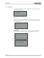
HS1
HS2
HW1
Time / Extra timers
Holiday
Energy/Cold water
Running mode
Access Rights
Sometimes there are further submenus linked to a menu or menu item.
Additional menus are indicated by an arrow symbol in the right corner of the
display. Use the Right button to select them. Use the Left button to go back one
menu level.
P100013121 A
15/36
flexotron®800
The menu system
HS1..HS3, HW1..2, CS1, … (controller systems)
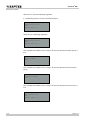
The setpoints and actual values can be viewed in the various controller systems,
the controller properties can be set, and manual mode can be activated.
Time / Extra timers
The time, date and set periods of use are shown here. Values can only be changed
with Operator or Admin access level.
Holiday
Holiday times are displayed here. Up to 24 separate holiday periods can be
configured for a whole year in advance. Values can only be changed with Operator,
or Admin access level.
Running mode
Access to the alarm tab for reading the current values and the alarm log.
The Inputs/Outputs submenu displays the raw values from the sensors, the signals
at the analogue outputs and the current status of the digital inputs and outputs.
Access rights
In this menu you can change to a higher access level. In addition, you can change
the password or log out of the current access level and continue on the basic level.
4.1.1 Editing parameters
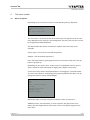
You can edit parameters in some menus. This option is indicated by the flashing
yellow LED
.
If the LED flashes rapidly (twice per second), the parameters can be changed
using the current access level.
If the LED flashes more slowly (once per second), a higher access level is required
to edit the parameter.
To edit a parameter, first press the OK button. If you need a higher access level to
edit the parameters, a corresponding login menu appears (see below). Otherwise,
the cursor appears next to the editable values. Press the Up and Down buttons to
edit the value.
In numbers containing several digits you can move between the digits using the
Left and Right buttons.
When the required value is displayed, press OK.
If there are other editable values, the cursor automatically moves to the next one.
To skip a value without editing it, press the Right button.
16/36
P100013121 A
flexotron®800
The menu system
To reverse a change and return to the original setting, press and hold the C button
until the cursor disappears.
The following section contains some of the menus which display controller systems,
timer outputs, holidays, alarms and the status of inputs and outputs.
4.2
HS1..HS3, HW1..2, CS1, …
Actual/setpoint
Temp control
Manual/auto
HS1 ECO/comf mode
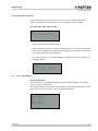
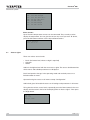
If you select one of the various controller systems, four submenus are displayed,
with the exception of the additional control loop and HP, where only two submenus
(Actual/setpoint and Manual/auto) are available.
The systems that you can then access depend on which inputs and outputs are
configured.
4.2.1 Actual/setpoint
HS1, HS2 and HS3
Outside temp: -5 °C
HS1
Act: 49.8 °C Setp.→
Setp.: 55.0 °C
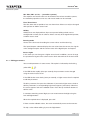
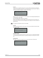
Weather-dependent setpoint submenu:
Here you can set the supply temperature for a particular outside temperature.
You can set 8 schedule start points for each system.
The values in between must be calculated by linear interpolation. Only the
values for the supply temperature can be changed on the flexotron®800. The
outside temperature values can be changed using CASE flexotron®.
Outd comp setp HS1
-20 °C = 67 °C
-15 °C = 63 °C
-10 °C = 59 °C
P100013121 A
17/36
flexotron®800
The menu system
The heating systems have individual pump stop temperatures for day and night.
Pump stop HS1:On
Stop temp day: 17°C
Stop temp night: 17°C
Hysteresis: 2.0 °C
Submenu: Room-temperature sensor
Room temperature setpoint configuration. This menu is only available if the
room temperature sensor is configured.
Room sensor HS1
Act: 20.8 °C
Setp: 21.0 °C
Submenu: Return temperature
Return temp
HS1: 28.0 °C
CS1
The setpoint for the cooling system can be fixed or weather-dependent. With a
constant setpoint:
CS1
Act: 13.0 °C
Setp:13.0 °C
With a weather-dependent setpoint:
Outside temp: 21.8°C
CS1
Act: 13.2°C Setp. ->
Setp: 13.0°C
Press the Right button to go to set the supply temperatures for particular outside
temperatures when a weather-dependent setpoint is selected. You can set up to
eight schedule start points.
18/36
P100013121 A
flexotron®800
The menu system
Outd comp setp CS1
20 °C = 15 °C
22 °C = 14 °C
24 °C = 13 °C
The cooling system has individual pump stop temperatures for day and night.
Pump stop CS1:On
Stop temp day: 15°C
Stop temp night 15°C
Hysteresis: 2.0 °C
HW1 and HW2
Actual value and setpoint for domestic hot water.
Supply temp. HW1
Act: 53.0 °C
Setp: 55.0 °C
HP1
Actual value and setpoint for hot water preparation
Supply HP1
55.0°C
Boiler
Different screen displays appear, depending on the type of setpoint selected for
boiler control.
Alternative 1 – constant setpoint:
HB setp:
36 °C
HB act.:
36.5 °C
P100013121 A
19/36
flexotron®800
The menu system
Alternative 2 – control loop setpoint:
HS-depending setp
+ 5.0 °C
HB setp: 43.0 °C
HB act.: 43.2 °C
Alternative 3 – weather-dependent setpoint:
Outside temp: 5 °C
HB
Act.: 43.3 °C Setp ->
Setp: 43.0 °C
To set the weather-dependent characteristic, eight points:
Outd
-20
-15
-10
comp
°C =
°C =
°C =
setp HB
67 °C
63 °C
59 °C
4.2.2 Temperature control
P-band and I-time settings of the various controllers.
HS1
P-band: 100.0 °C
I-time: 100.0 s
Submenu: Only available for HS1 and HS2.
HS1 Return temp.
P-band: 100.0 °C
I-time: 100.0 s
20/36
P100013121 A
flexotron®800
The menu system
4.2.3 Manual/auto
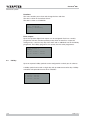
All configured control loops can be manually controlled between 0 and 100%. All
configured pumps can be set to Auto, On or Off.
If an output is manually controlled, it means that normal regulation is disabled. For
this reason, an alarm is generated whenever an output is set to an operating mode
other than Auto.
The menu display depends on the configuration, which is why not all the screens
are shown here.
HS1..3, HW1..2, CS1
Manual operation / reading control signals for the actuators.
Manual/auto
HS1
Auto
Manual mode: 37
Submenu: For manual operation or reading the pumps
Manual/auto HS1
P1A: Auto
P1B: Auto
Boiler
Menu for setting the burners, circulation pumps, return valves and transport pumps
to manual mode. The menu structure depends on the configuration.
Alternative 1, Off/On:
Boilers 1 to 4 can be set to Auto/Manual Off/Start1/Start2 with 2-step burners and
to Auto/Manual Off/Manual On with 1-step burners.
Manual/auto
Boiler 1: Auto
P100013121 A
21/36
flexotron®800
The menu system
Alternative 2, Off/On/modulating regulation:
If a modulating burner has been selected for boiler 1:
Manual/auto
Modulating boiler
Auto
Manual set: 2 %
Alternative 3, modulating regulation:
Manual/auto
Modulating boiler
Auto
Manual set: 56 %
The Auto/Manual Off/Manual On setting is for manual operation of boiler pumps 1
to 4.
Manual/auto
Boiler pump1:
Auto
The Auto/Manual Off/Manual On setting is for manual operation of the transport
pump.
Manual/auto
Transport pump:
Auto
The Auto/Manual Off/Manual On setting is for manual operation of return valves 1
to 4.
Manual/auto
HB1 return temp
Auto
Manual mode: 0.0
22/36
P100013121 A
flexotron®800
The menu system
4.2.4 ECO/comfort function
Two comfort temperature periods can be set for every day. When the heating
system is outside its comfort periods, it is put into ECO (economy) mode.
HS1, HS2, HS3, HW1, HW2 and CS1
HS1 ECO/comf mode
On →
5°C (room temperature)
Submenu: Setting the comfort periods.
Each controller system has 8 separate setting menus – one for every day of the
week and an additional one for the holiday programme. The holiday programme
has priority over the other programmes.
For all-day operation, set a period of 00:00 – 24:00. To deactivate a period, set it
to 00:00 – 00:00.
HS1 Comfort time
Monday
Per 1: 07:00 – 16:00
Per 2: 00:00 – 00:00
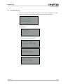
4.3
Time / timer outputs
General information
The controller has a calendar programme where weekly schedules and holidays
can be set for the whole year.
The switch between summertime and wintertime is performed automatically. To see
timer outputs 1-5 in the display, they must first be configured.
Time/Date
Timer output
Timer output
Timer output
Timer output
Timer output
P100013121 A
1
2
3
4
5
23/36
flexotron®800
The menu system
Time/Date
This menu enables you to view and change the time and date.
The time is shown in the 24-hour format.
The date is shown as YY:MM:DD.
Time: 18:21
Date: 13:11:25
Weekday: Wednesday
Timer outputs
Up to five separate digital timer outputs can be configured. Each has a weekly
programme with two activation periods per day. Each channel has 8 separate
setting menus – one for every day of the week and an additional one for the holiday
programme. The holiday programme has priority over the other programmes.
Timer output 1
Monday
Per 1: 07:00 – 16:00
Per 2: 00:00 – 00:00
4.4
Holiday
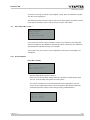
Up to 24 separate holiday periods can be configured for a whole year in advance.
A holiday period can be both a single day and up to 365 consecutive days. Holiday
schedules take precedence over other schedules.
Holidays
1: 01:01
2: 09:04
3: 01:05
24/36
(mm:dd)
- 02:01
– 12:04
- 01:05
P100013121 A
flexotron®800
The menu system
4.5
Energy/Cold water
This menu displays the readings from the pulse meter inputs. The pulse constants
(pulses per unit) are defined in the Configuration/Pulse constants menu.
Heating meter
Cold water meter 1
Cold water meter 2
Electricity meter
Leakage monitoring
Heating meter
Energy total
1532.3 MWh
Hot water total
387.02 m3
The values below can be reset.
Energy
Today: 28.15 kWh
Yesterday: 123.45 kWh
D B Y-day: 132.11 kWh
Usage
Today: 28.15 l
Yesterday: 123.45 l
D B Y-day: 132.11 l
Power usage
Instant: 2100.0
Average/h: 3200.0
Max aver.: 5300.0
P100013121 A
25/36
flexotron®800
The menu system
Cold water meters CW1 and CW2
CW1 Usage total
276.22 m3
CW2 Flow
156.4 l/min
CW1 Usage
Today: 88.1 l
Yesterday: 4123.4 l
D B Y-day: 5012.1 l
Lowest CW1 usage
Today: 0.1 l/h
Yesterday: 0.2 l/h
Electricity meter
Energy total
1866.54 MWh
This value can be reset.
Leakage monitoring
Leakage monitoring
1.31 kW
26/36
P100013121 A
flexotron®800
The menu system
4.6
Running mode
You cannot make changes in the Running mode menu. It is simply for viewing the
current values and alarm log.
Alarms
Inputs/Outputs
Extra Sensors
Alarms
The alarm log of the flexotron®800 contains the 40 most recent alarms. The latest
event is at the top of the list. The alarm log is solely for viewing alarms in order to
assist troubleshooting.
14 Jul 18:57 B
Sensor error CS1
Return
Acknowledged
Inputs/Outputs
The Inputs/Outputs menu displays the raw values from the sensors, the signals at
the analogue outputs and the current status of the digital inputs and outputs.
AI
DI
UI
AO
DO
AI1:
AI2:
AI3:
AI4:
P100013121 A
-3.5
53.7
54.8
50.6
Outd temp
HS1 Supply
HW1 Supply
HS1 Return
27/36
flexotron®800
The menu system
DO1:
DO2:
DO3:
DO4:
DO5:
DO6:
DO7:
On HS1-PumpA
Off HS1-PumpB
Off Inc HS1-Act.
On Dec HS1-Act.
On HW1-Pump
On HS2-PumpA
On Sum alarm
Extra sensors
Up to five extra temperature sensors can be connected. They are only used to
display the temperature. You can give the sensors any name you want. To do this,
press the OK button and then use the Up and Down buttons.
Extra Sensor1
Act: 51.2 °C
4.7
Access rights
There are various access levels:
• Basic (the lowest level, where no login is required)
• Operator
• Admin
Admin is the highest level with the most access rights. The access level determines
which menus and editable parameters are displayed.
Basic level permits changes in the operating mode and read-only access to a
limited number of menus.
Operator level gives access to all menus except “Configuration”.
Admin level gives full read/write access to all settings and parameters in all menus.
To log into the various access levels, repeatedly press the Down button in the start
display until the arrow in the left of the display points to “Access rights”. Then press
the Right button.
Log on
Log off
Change code
28/36
P100013121 A
flexotron®800
The menu system
Log on
In this menu it is possible to log into any access level by entering the appropriate
4-digit password (code). The menu is also displayed if you try to access a menu or
carry out a function that requires a higher access level.
Log on
Enter code:****
Actual level: None
When you press the OK button, the cursor jumps to the first digit. Repeatedly press
the Up button to set the digit.
Press the Right button to go to the next digit.
Repeat the procedure for all four digits of the password. Press OK to confirm. An
info text with the current access level appears in the display. Use the Left button to
quit this menu.
The code for the Operator access level is 3333.
Log off
Use this menu to log out from the current access level to the Basic level that does
not require a login.
Log off?
No
Present level:Admin
Automatic logout
If the access level is Operator, Service or Admin, the user is automatically logged
out and returned to Basic level after a period of inactivity. The time for this can be
set.
Change code
The code can only be changed for the current access level or a lower one.
Change code for: Operator
New code: ****
P100013121 A
29/36
flexotron®800
30/36
P100013121 A
flexotron®800
Other functions
5
Other functions
5.1
Alarm handling
If an alarm occurs, the red alarm LED
flashes either on the front panel of
controllers with a display or on an external display. The LED flashes as long as
there are unacknowledged alarms.
Alarms are logged in the alarm list. The list shows the type of alarm, the date and
the time, and the alarm class (A, B or C).
Press the alarm button on the front panel to see the alarm list.
Sensor error
24 Aug 10:43 Class:B
Reset ▼
If there are several alarms, two arrows (up/down) appear on the right of the display.
Use the Up and Down buttons to scroll to the other alarms.
The alarm status is shown in the bottom left of the display. For active,
unacknowledged alarms this field is blank. Unacknowledged alarms that have been
reset are marked as returned. Acknowledged alarms or alarms that are blocked but
still active are indicated as acknowledged or blocked.
In order to acknowledge an alarm, you must first press OK. You can then either
acknowledge the alarm or block it.
Acknowledged alarms remain on the alarm list until the cause of the alarm has
been eliminated.
Blocked alarms remain on the alarm list until the cause of the alarm has been
eliminated and the block has been removed. New alarms of the same type will not
be activated as long as the block remains.
Because blocking alarms can be potentially hazardous, you need a high user
access level to do this.
Class A and B alarms activate alarm outputs if these have been configured.
Class C alarms do not activate the alarm outputs.
Class C alarms are removed from the alarm list when the alarm inputs are reset,
even if they are not acknowledged.
P100013121 A
31/36
flexotron®800
Other functions
5.2
Individual text field
If you press the Right button in the start menu, a display appears with a text that
you can customise.
You can use the text for the name of the installing company, for service contacts
and telephone numbers or other information.
The easiest way is to enter the text using CASE flexotron®, but you can also use
the buttons. Up to four lines, each with 20 characters, can be individually edited.
5.3
Version number
Press the Right button twice in the start menu to see the version number of the
program and the ID number in the display.
5.4
Language
If you press the Right button three times in the start menu, a menu for setting the
language appears in the display.
The various languages are stored in the controller application memory and are
loaded to the RAM.
If a newer version than the factory setting has been loaded to the flexotron®800
controller using CASE flexotron®, no language can be loaded from the application
memory. The language file may not be compatible with the newer version. This
means you are restricted to the two languages loaded from CASE flexotron®.
32/36
P100013121 A
flexotron®800
Other functions
5.5
Indicator LEDs
The status is shown in the upper left corner of the controller. On controllers with a
display, the alarm indicator and mode selection LEDs are beside the buttons.
5.5.1 Status indicator
Information
Colour
Description
Tx
Green
Interface 1, send
Rx
Green
Interface 1, receive
Serv
Yellow
Not used
LAN (web models)
Yellow/green
Green: Connection to other
network devices
Network data transfer
Flashing green
For identification
Flashing yellow:
P/B (power supply / battery)
Green/red
Power supply on / battery fault
Red
Alarm display
Yellow
Input mode
Controller with built-in
display:
5.6
Changing the battery
The flexotron®800 controller has a back-up battery for the memory and real-time
clock in the event of a power failure.
If the “internal battery” alarm is triggered and the battery LED lights up red, the
battery must be replaced. A back-up capacitor protects the content of the memory
for at least 10 minutes without power.
The battery may only be changed by trained staff.
P100013121 A
33/36
flexotron®800
Other functions
5.7
Start assistant
When the controller is switched on for the first time, it runs through a special
procedure:
1. Select one of the following applications by pressing the Down button:
• Ventilation
• Heating
2. Continue using the Right button.
3. Select the application using the OK button.
ÂÂ The cursor jumps to “Accept changes: No”.
4. Press the Up or Down button until the display changes to Yes.
5. Press OK to confirm.
ÂÂ The program loads and the default display appears.
The controller switches to normal operation. This procedure will not be repeated the
next time that the application is launched.
5.8
Basic configuration for heating
The start assistant (see previous section) selects a configuration for each type of
device. This configuration can be applied without changes, or can be used as a
starting point for individual customisations.
34/36
P100013121 A
flexotron®800
Illustrations
Illustrations
Fig. 1
Fig. 2
Fig. 3
Fig. 4
Fig. 5
P100013121 A
Picture of flexotron®800 Heating circuits with the maximum number of available elements
Cooling circuit with the maximum number of available elements
Domestic hot water with the available elements
Boiler circuits with two of the maximum four available boilers.
7
8
9
10
11
35/36
Printed in Switzerland
© Fr. Sauter AG
Im Surinam 55
CH-4016 Basel
Tel. +41 61 - 695 55 55
Fax +41 61 - 695 55 10
www.sauter-controls.com
[email protected]