1
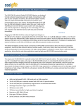
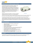
Introduction & Specifications of Hi-Speed VScom USB-to-Industrial Quad RS-422/485 Adapter USB to Quad Opto-isolated RS-422/485 Adapter (USB-4COMi-SI-M) - with optical isolation (2000V) - with surge protection (25KV ESD) on all signal lines to prevent interference, to protect system and minimize down time USB to Quad RS-422/485 Adapter (USB-4COMi-M) Introduction of USB-4COMi-M & USB-4COMi-SI-M The USB to Industrial Quad RS-422/485 Adapter is designed to make industrial communication port expansion quick and simple. Connecting to a USB port on your computer or USB hub, the USB to Industrial Quad RS-422/485 Adapter instantly adds four industrial communication ports to your system. By taking advantage of the USB bus, the USB Industrial Quad RS-422/485 Adapter makes it easier than ever to add RS-422 or RS-485 device to your system with easy plug-and-play and hot plug features. Adapting the new technology, the industrial I/O communication port expansion now takes the new bus with easy and convenient connectivity. Plugging the USB to Industrial Quad RS-422/485 Adapter to the USB port, the adapter is automatically detected and installed. There are no IRQ & COM port conflicts, since the port doesn't require any additional IRQ, DMA, memory as resources on the system. The RS-422 / 485 ports function as native Windows COM ports, and all the ports are compatible with Windows serial communication applications. The USB to Industrial Quad RS-422/485 Adapter provides instant connectivity to four RS-422/485 communication devices for factory automation equipment, multi-drop data collection devices, barcode readers, time clocks, scales, data entry terminals, PC to PC long distance communications and serial communication in harsh environments. The USB Industrial I/O provides industrial solution for applications requiring single node or multi-drop communications over short and long distance. Optical Isolation & Surge Protection (Only USB-4COMi-SI-M provides this function) Optical isolation and surge protection are available to this product USB-4COMi-SI-M. Each RS-422/485 port is individually optically isolated with 2000 Volt DC optical isolation. The optical isolation protects your PC or notebook from spikes and surges on the RS-422/485 network, by converting the electrical pulse into an optical signal and then changing it back into an electrical pulse. Your computer is well protected, since the surges and spikes cannot cross the optical link. Each RS-422/485 port is individually protected by surge protector to withstand electrostatic discharge and power surges up to 25KV ESD. Surge suppression on all signals prevent from damages caused by lightning or high voltage. USB-4COMi-M & USB-4COMi-SI-M USB-to-Quad RS-422/485 User’s Manual 1 Specifications & Features USB to Quad Opto-isolated RS-422/485 Adapter (USB-4COMi-SI-M) Adds quad high speed RS-422 / 485 ports via USB connection Each RS-422/485 port is individually optically isolated with 2000 Volt DC optical isolation. Each RS-422/485 port is individually protected by surge protector to withstand electrostatic discharge and power surges up to 25KV ESD. 384 byte receive buffer 128 byte transmit buffer for high speed data throughput Requires no IRQ, DMA, I/O port Data rates: 300 bps to 1M bps Serial Connector: four DB-9 male connectors Auto transmit buffer control for 2-wire RS-485 half-duplex operation Termination resistors installed on-board. RS-422 data signals : TX-, TX+, RX+, RX-, GND, RTS-, RTS+, CTS+, CTSRS-485 data signals: Tx-, Tx+, Rx+, Rx-(4 wire) and data-, data+ (2 wire). Monitor LEDs of TxD, RxD indicating port status Self-powered. Power adapter of 5V, 1.6 Amp included Virtual COM port drivers available for Windows 7, Vista, 2003, XP, 2000. USB to Quad RS-422/485 Adapter (USB-4COMi-M) Adds quad high speed RS-422 / 485 ports via USB connection 384 byte receive buffer 128 byte transmit buffer for high speed data throughput Requires no IRQ, DMA, I/O port Data rates: 300 bps to 1M bps Serial Connector: four DB-9 male connectors Auto transmit buffer control for 2-wire RS-485 half-duplex operation Termination resistors installed on-board. RS-422 data signals : TX-, TX+, RX+, RX-, GND, RTS-, RTS+, CTS+, CTSRS-485 data signals: Tx-, Tx+, Rx+, Rx-(4 wire) and data-, data+ (2 wire). Monitor LEDs of TxD, RxD indicating port status Self-powered. Power adapter of 5V, 1.6 Amp included Virtual COM port drivers available for Windows 7, Vista, 2003, XP, 2000. Power Supply This 4-port RS-422/485 Adapter is provided with an external switching power adapter in the package. USB-4COMi-M & USB-4COMi-SI-M USB-to-Quad RS-422/485 User’s Manual 2 Hardware Installation Outside the unit, there are four 4-pin DIP switches which are set to select the mode of operation. You will need to set the switch settings to RS-422 mode, or RS-485 mode, as per the requirements of your application. After setting of switches and connecting power supply to the adapter, you then plug the adapter to USB port to start driver installation. The RS-422 & RS-485 Mode Block Configuration Settings are listed as follows. RS-422 & RS-485 Mode Block Configuration SW1 (PORT1), SW2 (PORT2), SW3 (PORT3), SW4 (PORT4) RS-422 Operation Mode S1 S2 4 wire with handshaking ON ON S3 S4 OFF OFF RS-485 Full Duplex (4 wire) ON Half Duplex (2 wire) with Echo Half Duplex (2 wire ) without Echo OFF OFF OFF ON Note OFF OFF OFF ON ON Note OFF OFF Note : In the most common situation , a 120 Ohm termination resistor of TxD (S4 is ON ) is required in a RS485 Half Duplex configuration. Otherwise it is rarely used. Inside the unit, there are four 6x2 (8pin) header blocks which are jumpered to enable Rx, CTS 120 Ohm termination resistors and RX, Tx 750 Ohm biasing resistor. You will need to open up the case and set the jumper setting for RS-422 mode or RS-485 mode as per the requirements of your application. Settings are listed as follows. USB-4COMi-M & USB-4COMi-SI-M USB-to-Quad RS-422/485 User’s Manual 3 JP5 (PORT1), JP6 (PORT2), JP7 (PORT3), JP8 (PORT4) for Termination and Biasing Option Configuration Jumper 1-2 3-4 5-6 7-8 9-10 11-12 Function Pull-up Tx+ to VCC by 750 Ohm Bias resistor. This jumper should be populated for pull-up Tx+. Pull-down Tx- to GND by 750 Ohm Bias resistor. This jumper should be populated for pull-down Tx-. Rx+/- Termination of 120 Ohm. This jumper should always be populated forRS-422 and RS485 Full-Duplex mode. Pull-up Rx+ to VCC by 750 Ohm Bias resistor. This jumper should be populated for pull-up Rx+. Pull-down Rx- to GND by 750 Ohm Bias resistor. This jumper should be populated for pull-down Rx-. CTS Termination of 120 Ohm. This jumper should always be populated for RS-422 mode. Note : Sometimes, when operating in RS-422 or RS-485, it is necessary to configure termination and biasing of the data transmission lines. Generally this must be done in the cabling, since this depends on the installation of connections. Before applying the option, check your cable specification for proper impedance matching. Biasing of data lines must only occur at a single point anywhere in the cabling. USB-4COMi-M and USB-4COMi-SI-M provide biasing for ease of installation. Please be sure to disable this inside the unit, if your cabling already provides biasing. Termination must not be installed in the middle of the cable. It is only permitted at both ends. Since a computer controlled serial port is almost always at one end of the cable, termination is enabled by default. Rx-Termination is inside the box, because you hardly ever need to change it. Tx-Termination is used in Half-Duplex modes. In this situation data is sent and received via Tx+/- lines. Therefore Tx-Termination is done via DIP-Switch (see S4 above). USB-4COMi-M & USB-4COMi-SI-M USB-to-Quad RS-422/485 User’s Manual 4 Windows 7/ Vista / 2003 / XP / 2000 Driver Installation You need to have administrator privileges to install any new drivers under Windows 7/ Vista / 2003/ XP / 2000. To install the driver or update the configuration please log onto Windows as "Administrator" or ask your system administrator to install the USB-COM driver. You need to install driver first, prior to hardware installation. Do not connect the USB-to-Serial Adapter to the USB port of your computer, before you finish driver installation. Please proceed with the following steps to install the driver: 1. 2. 3. 4. 5. 6. Insert the “USB COM Series Driver and Utility” CD into your CD-ROM. The “USB COM Series Driver and Utility CD” dialog box appears. Under “Driver Installation”, double click “Windows 7, Vista, 2003, XP, 2000 driver” to install the device driver. The USB COM install program will auto-detect the OS type and install the driver automatically. (Note: in Windows 7 or Vista OS you will find another dialog box, please click on “OK” to confirm the drivers install program). After the message “FTDI CDM Driver installation process completed” appears, press “Enter” to complete the driver installation. Plug in the USB to Serial Adapter to the USB port of your computer. Windows will finish installing the driver files. Check Installation You can now verify the installation has been completed successfully by looking under Device Manager of the System Properties screen. (Go there by Start-SettingControl Panel-System Properties-Hardware-Device Manager. The device should have installed as a "USB Serial Port (COMx)" attached to "USB Serial Converter (A/B or A/B/C/D)". USB-4COMi-M & USB-4COMi-SI-M USB-to-Quad RS-422/485 User’s Manual 5 Change COM Port Properties & COM Port Number This feature is particularly useful for programs, such as HyperTerminal, which only work with COM1 through COM4. Please ensure that you do not change the COM Port Number already in use. To change the virtual COM port properties: Select the "USB Serial Port" Click “Properties”. Select "Port Setting" and “Advanced”. Click the drop down arrow on COM Port Number and scroll to the required COM port. Select "OK". Return to the Device Manager Screen. You will see that the USB Serial Port installation has been changed to the new COM Port Number. Uninstalling Windows 2003/XP/2000 Drivers Please proceed with the following steps to uninstall the 2003/XP/2000 driver: 1. Insert the “USB COM Series Driver and Utility” CD into your CD-ROM. 2. The “USB COM Series Driver and Utility CD” dialog box appears. 3. Under “Driver Uninstalling”, double click “Windows 2003, XP, 2000 driver uninstall” to uninstall the device driver. 4. When following dialog box appears, double click “Clean System” to uninstall the 2003/XP/2000 drivers. 5. You need to disconnect all USB to serial Adapters from your PC, when the message below appears. Double click “OK” to start uninstalling Windows 2003/XP/2000 USB to Serial drivers. USB-4COMi-M & USB-4COMi-SI-M USB-to-Quad RS-422/485 User’s Manual 6 6. Double click “Yes” to confirm it. 7. Click “No” to proceed. 8. When the message “Status: System clean completed” appears, double click “Exit” to complete the USB to serial drivers uninstall. 9. Press “Start” button and select “Control Panel”. USB-4COMi-M & USB-4COMi-SI-M USB-to-Quad RS-422/485 User’s Manual 7 10. Open the Add or Remove program. 11. Remove the first “Windows Driver Package – FTDI CDM Driver Package (…)”. 12. Click “Chang/Remove” and “Yes” to remove the first Windows Driver Package. 13. Remove the second “Windows Driver Package – FTDI CDM Driver Package (…)”. 14. Click “Chang/Remove” and “Yes” to remove the second Windows Driver Package. 15. Reboot the computer to complete the driver uninstall. USB-4COMi-M & USB-4COMi-SI-M USB-to-Quad RS-422/485 User’s Manual 8 Uninstalling Windows 7 or Vista Drivers Windows 7 and Vista have many new security features. You need to proceed with the following steps to uninstall the Vista driver: 1. The USB to serial devices must connect to the PC. 2. Press “Start” button and select “Control Panel”. 3. Select “Classic View” from the top left hand corner and then “System” from the list. 4. Select “Device Manager” from the top left hand corner. 5. Locate your Device under the Ports (COM & LTP) section and right click on it to bring up the menu shown. USB-4COMi-M & USB-4COMi-SI-M USB-to-Quad RS-422/485 User’s Manual 9 6. Select uninstall and be sure to click the box for “Delete the driver software for this device” in the next window and press “OK”. Note: if you have more than one USB Serial Port (COMx) installed in your PC, you need to repeat from step 5 to step 6 to delete the driver software for each port. 7. Locate your Device under the Universal Serial Bus Controllers section, and right click on it to bring up the menu shown. USB-4COMi-M & USB-4COMi-SI-M USB-to-Quad RS-422/485 User’s Manual 10 8. Select uninstall and be sure to click the box for “Delete the driver software for this device” in the next window and press “OK”. Note: if you have more than one USB Serial Converter installed in your PC, you need to repeat step 7 and step 8 to delete the driver software for all devices. RS-422 Signal Pin-outs of DB-9 Male Pin 1 Pin 2 Pin 3 Pin 4 Pin 5 Pin 6 Pin 7 Pin 8 Pin 9 USB-4COMi-M & USB-4COMi-SI-M TxD- (A) TxD+(B) RxD+(B) RxD-(A) GND RTS- (A) RTS+(B) CTS+(B) CTS- (A) USB-to-Quad RS-422/485 User’s Manual 11 RS-422 Signal Wiring Point-to-Point 4-Wire Full Duplex USB-4COMi-M 2 1 3 4 5 TxD+(B) TxD- (A) RxD+ (B) RxD- (A) GND RS-422 Device RxD+ (B) RxD- (A) TxD+(B) TxD- (A) GND RS-422 with Handshaking USB-4COMi-M 2 1 3 4 5 7 6 8 9 TxD+(B) TxD- (A) RxD+ (B) RxD- (A) GND RTS+(B) RTS- (A) CTS+(B) CTS- (A) RS-422 Device RxD+ (B) RxD- (A) TxD+(B) TxD- (A) GND CTS+(B) CTS- (A) RTS+(B) RTS- (A) RS-485 4-Wire (Full duplex) Signal Pin-outs of DB-9 Male Connector Pin 1 Pin 2 Pin 3 Pin 4 Pin 5 USB-4COMi-M & USB-4COMi-SI-M TxD- (A) TxD+(B) RxD+(B) RxD-(A) GND USB-to-Quad RS-422/485 User’s Manual 12 RS-485 2-Wire (Half duplex) Signal Pin-outs of DB-9 Male Connector Pin 1 Pin 2 Pin 5 Data- (A) Data+(B) GND RS-485 Signal Wiring Point-to-Point 4 Wire Full Duplex USB-4COMi-M 2 1 3 4 5 TxD+(B) TxD- (A) RxD+ (B) RxD- (A) GND RS-485 Device RxD+ (B) RxD- (A) TxD+(B) TxD- (A) GND Multidrop RS-485 2-Wire Half-duplex USB-4COMi-M 2 Data+(B) 1 Data- (A) 5 GND RS-485 Device Data+(B) Data- (A) GND | | | | | RS-485 Device x Data+(B) Data- (A) GND All brand names and trademarks are the property of their respective owners. Manual Part No.: USBG057 USB-4COMi-M & USB-4COMi-SI-M USB-to-Quad RS-422/485 User’s Manual 13