1
FACTORY AUTOMATION
INVERTER
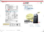
FR-A800 Plus
The optimum functions for cranes are added.
C
M
Y
CM
MY
CY
CMY
K
Mitsubishi Electric Corporation Nagoya Works is a factory certified for ISO14001 (standards for
environmental management systems)and ISO9001(standards for quality assurance management systems)
for CRANES
Reduction in tact time
Load slippage prevention
HEAD OFFICE: TOKYO BLDG., 2-7-3, MARUNOUCHI, CHIYODA-KU, TOKYO 100-8310, JAPAN
L(NA)06098ENG-A(1507)MEE
Dedicated monitoring
functions
Applicability in a wide
range of industries
Easier maintenance
Approach to the leading
drive performance
Contents
Global Player
GLOBAL IMPACT OF
MITSUBISHI ELECTRIC
5
1
Standard specifications
11
2
Outline dimensions
15
3
Crane function parameters
17
4
Warranty
23
5
Support
24
6
Features
C
M
Y
CM
MY
CY
CMY
Through Mitsubishi Electric’s vision, “Changes for the Better“ are possible for a brighter future.
K
Mitsubishi Electric is involved in many areas including the following
We bring together the best minds to
create the best technologies. At
Mitsubishi Electric, we understand that
technology is the driving force of
change in our lives. By bringing greater
comfort to daily life, maximising the
efficiency of businesses and keeping
things running across society, we
integrate technology and innovation to
bring changes for the better.
Energy and Electric Systems
A wide range of power and electrical products from generators to large-scale displays.
Electronic Devices
A wide portfolio of cutting-edge semiconductor devices for systems and products.
Home Appliances
Dependable consumer products like air conditioners and home entertainment
systems.
Information and Communication Systems
Commercial and consumer-centric equipment, products and systems.
Industrial Automation Systems
Maximising productivity and efficiency with cutting-edge automation technology.
1
2
SPECIALTY
Pursuing optimum functions to
A new lineup of dedicated inverters for specialized fields are born!
!
3
The optimum functions for each dedicated field are added to the already high
meet our customers' needs
performance and high functionality FR-A800 series inverter. for CRANES
4
Features
Features
Suited for various cranes to achieve
fast, robust, and smooth operations
! Reduction in tact time
By using the Mitsubishi's original anti-sway control technology, the swinging of an object moved by a crane is suppressed
at the time of stopping, even without operator's input adjustment.
This control cuts down the tact time and facilitates efficient operation.
With anti-sway control
Without anti-sway control
Trolley wire
Trolley wire
Trolley wire
Horizontal movement
Traverse motor
Hoisting motor
IM
IM
Electric chamber
Traction motor
Traction motor
G
C
IM
Crane
IM
G
Trolley wire
Electric chamber
Wheel
Rail
Horizontal movement
Traverse motor
Hoisting motor
IM
IM
Traction motor
G
IM
Traction motor
Crane
IM
M
Y
W
CM
W
W
W
G
Wheel
Rail
4
3
2
1
0
-1
-2
-3
-4
With anti-sway control
Brake sequence function
Falling detection
The highly scalable brake sequence function enables the output of a brake
opening signal for the optimum brake operation calculated from the load torque
or the speed.
The function enables setting of the brake opening level individually for forward
rotation and reverse rotation.
Slippage during the start of a lift can
be checked.
When the commanded direction
differs from the actual motor rotation
direction, the falling detection signal is
output.
Low-speed range speed control P gain
1
Features
Features
Anti-sway control
Position of traverse axis [m] Swing angle of load [Degrees]
1
! Load slippage prevention
When an inverter is connected to a lift, the inverter has a load immediately after
the lift brake is released. Adjusting the speed control P gain in the low-speed
range improves the response at low speed, and shortens the time from startup
to brake opening.
Without anti-sway control
0
5
10 15 20 25 30 35 40 45 50
Time [s]
6
5
4
3
2
1
0
-1
0
5
10 15 20 25 30 35 40 45 50
Time [s]
MY
CY
CMY
K
Load torque high-speed
frequency control
(mode 2)
When there is a light-load (when light
loads are moved up or down by a
crane), the speed will automatically
be increased. This reduces the tact
time and facilitates efficient operation.
The possible operation speed is set
automatically according to the load.
After starting the inverter, the inverter
runs at high speed with a light load.
Shortest-time torque
startup function
The time from the start command to
when the brake opens is shortened.
This will contributes to reduction in
tact time.
• Shortest-time torque startup function
The optimum distribution of the
excitation current and torque
current enables rapid startup of the
torque.
• Magnetic flux command
during pre-excitation
Decreasing the pre-excitation
current during a motor stop
reduces power consumption
during standby, and enables rapid
startup of the torque.
5
Shortest-time torque startup: disabled
Pre-excitation: disabled
Start command
Brake opening
400ms
400
ms
Speed
100%
! Dedicated monitoring functions
Wide range applications
Torque
100%
Magnetic flux
Shortest-time torque startup: enabled Start command Brake opening
Pre-excitation: disabled
300
ms
300ms
Speed
100%
Torque
100%
Magnetic flux
Shortest-time torque startup: enabled
Start command Brake opening
Pre-excitation: enabled (35%)
190 ms
Excitation startup
Speed
100%
Torque
Magnetic flux
35%
100%
Overload detection function
By outputting an overload detection
signal when too much load (overload)
is applied to a crane, this information
can be transmitted to the superordinate controller.
During constant speed operation,
when the motor torque is equal to or
higher than the torque setting for the
time setting or longer, the overload
detection signal is turned ON.
Start count monitor
The inverter starting times can be
counted.
Confirming the starting times can be
used to determinate the timing of the
maintenance, or can be used as a
reference for system inspection or
parts replacement.
Compliance with ship
classification standards
Using the recommended noise filter in
combination with the inverter
supports compliance with various
countries ship classifications, such as
NK, LR, DNV, ABS, BV, CCS, and KR.
The FR-A800-CRN can be used for
electric deck cranes on ship.
Example of FR-A820-90K-1-60CRN and SF-THY (90 kW)
Start count monitor
6
Features
Features
Easier maintenance
Longer service life
[Long life components]
1
*1 Surrounding air temperature: Annual
average of 40℃ (free from corrosive gas,
flammable gas, oil mist, dust and dirt).
The design life is a calculated value from
the LD rating. The value is not a
guaranteed product life.
*2 Output current: 80% of the inverter LD
rating.
! Enhanced vibration
resistance
[Protection against vibration]
A strong vibration may occur in some
operating conditions, for example,
during the crane traveling. Inverters
with the components fixed on the
circuit board with an adhesive, or the
cables tied (fixed) together, are
available for enhanced vibration
resistance. (to be released soon)
Improved environmental
resistance
[Measures against dust, dirt, and corrosion]
Using the inverter in the dusty
environment may cause fault such as
a short circuit. The inverter with circuit
board coating (conforming to
IEC60721-3-3 3C2/3S2) ensures
reliability even in poor environments.
Furthermore, the inverter with plated
conductor is also available.
Approach to the leading drive performance
High response
C
The improved speed response ensures a minimal speed fluctuation to maintain a constant speed when the load fluctuates.
• Speed response
Real sensorless vector control
50 Hz*1 (A700: 20 Hz)
Vector control*2
130 Hz*3 (A700: 50 Hz)
Y
CM
MY
CY
80 ms
FR-A800
FR-A700
K
900
100 ms/div
Time (s)
[Example of the speed change when an impact load is applied]
( When the SF-PR 4P motor (3.7 kW) is used under Real sensorless vector control )
High torque at low speed
Our new inverter realizes smooth cargo handling work at low speed and high torque for the slow and stable movements required for heavy objects.
t directio
n
Stabilizer and encoder 2
Stabilizer and encoder 1
Spring
Travel wheel
Spring
Travel rail
Travel pulse
(FR-A8AP)
*1
Travel pulse
(FR-A8TP)
*2
Right edge wheel drive
Inverter
*1 FR-A8AP (plug-in option)
*2 FR-A8TP (control terminal option)
The travel axis reads the amount of
lifting/lowering movement (encoder
pulse) of the lift axis to calculate the
wire rope length.
The wire rope length according to the
operating condition can be applied to
the anti-sway control.
The lifting/lowering speed can be
slowed down when the rope length
reaches a predetermined value to
prevent the object from colliding into
the lift axis drum, etc.
Travel
motor
Encoder pulse
(Vector control compatible option)
Lifting
motor
xis
ta
Lif
m
dru
150
Torque (%)
150
Torque (%)
ovemen
200
200
80
80
0
Lift axis
0
200
400
600
800
1000
1200
1400
1600
1800
Travel axis
2000
-80
0
-150
50
150
-200
-80
-150
-200
7
Crane m
Application example 2:
Wire rope length measurement
0
Load torque
Enlarged view
of the low-speed range
Bridge
Left edge wheel drive
Inverter
100
• Starting torque (at 0.3 Hz)
Real sensorless vector control
200% (ND rating)
Vector control*2
200% (ND rating)
(150% of initial setting for 5.5K or
higher)
The traveled distance (total number of
travel pulses) of each wheel is directly
read from the encoder installed at the
wheel. The pulses from the two
wheels are then compared, and their
speed is adjusted to synchronize the
wheel positions. There is no need to
use an external controller to offset
speed, allowing high accuracy
control.
1
170 ms
Speed
0
Application example 1:
Position error correction
80 ms
Torque (%)
CMY
Inverter control such as inverter operations triggered by input signals, signal output based on inverter operation status,
and monitor output can be freely customized based on the machine specifications. Control programs can be created in
sequence ladders using the inverter setup software (FR Configurator2) (to be supported soon).
FR-A800
FR-A700
The improved speed response
ensures a minimal speed ctuation
when the load fluctuates.
170 ms
Speed (r/min)
M
Inverter operation sequence customized for the machine
Features
Features
The service life of the cooling fans*1
and the capacitors*1*2 is now 10
years. The service life can be further
extended by ON/OFF control of the
cooling fan.
Control the machines as you desire - PLC function
Speed (r/min)
[Example of speed-torque characteristics with Real sensorless vector control]
When offline auto tuning is performed for the SF-PR 4P motor (15 kW). In the low-speed
range, the torque increases by the increased magnetic excitation. Torque characteristics
in the low-speed range can be set in the parameters.
*1 At 3.7 kW with no load Differs depending on the load conditions and motor capacity.
*2 The vector control is available when a vector control compatible option is installed.
*3 When the option (FR-A8AP or FR-A8TP) is installed.
8
Features
Features
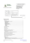
Delivering a comfortable inverter operating environment
―FR Configurator2 (to be supported soon)
1
Remote operation
Intuitive user interface
A USB connector (mini B connector)
is provided as standard. The connection with a personal computer can be
established easily without using a
converter.
Importing trace data or parameter
settings that have been copied in a
USB memory device to FR
Configurator2 enables analysis or
adjustment at a remote place.
Connected inverters are displayed in
a tree view. Windows of each function
can be switched using tabs, facilitating operations.
F R - A 8 2 0 - 0.4K
Symbol Voltage class
2
4
Symbol Structure/function
Tree view
Tab change
00023
0.4K
Three-phase
400 V class
FR-A840-[]
●
03250
110K
*4
●
Capacity*1
Standard model
0
200 V class
400 V class
Three-phase 200 V class 00046
0.4K
FR-A820-[]
*4
●
FR Configurator2
Mini B connector
• Standard model
Symbol Type
Description
00023 to 06830 Inverter SLD rated
current (A)
-1
-2
ND rated
0.4K to 280K Inverter
capacity (kW)
00077
0.75K
●
00038
0.75K
●
03610
132K
●
00105
1.5K
●
00052
1.5K
●
04320
160K
●
00167
2.2K
●
00083
2.2K
●
04810
185K
●
00250
3.7K
●
00126
3.7K
●
05470
220K
●
00340
5.5K
●
00170
5.5K
●
06100
250K
●
00490
7.5K
●
00250
7.5K
●
06830
280K
●
00630
11K
●
00310
11K
●
FM
CA*2
00930
18.5K
●
00470
18.5K
●
00770
15K
●
00380
15K
●
- 1 - 60 CRN
Symbol
Symbol Dedicated function
Circuit board coating
Plated conductor
(IEC60721-3-3 3C2/3S2 compatible)
60
06*3
01250
22K
●
00620
22K
●
With
With
01540
30K
●
00770
30K
●
CRN Dedicated to crane
Without
With
01870
37K
●
00930
37K
●
02330
45K
●
01160
45K
●
03160
55K
●
01800
55K
●
03800
75K
●
02160
75K
●
04750
90K
●
02600
90K
●
1
Features
Features
Easy USB cable connection
Lineup
• Separated converter type
F R - A 8 4 2 - 315K - 1 - 60 CRN
Personal computer
USB cable
Inverter
Symbol Voltage class
4
C
Symbol Structure/function
400 V class
Separated converter type
2
M
07700
Y
Efficient startup settings
CM
MY
• System setting
CY
Automatic recognition of connected inverters can also be set. The station
number, model, capacity, and any plug-in options of the connected inverters
can also be set manually.
CMY
K
Three-phase 400 V class
315K
FR-A842-
●
08660
355K
●
09620
400K
●
10940
450K
●
Capacity*1
Symbol Type
Description
Inverter SLD rated
current (A)
ND rated
315K to 500K Inverter
capacity (kW)
07700 to 12120
-1
-2
Symbol Dedicated function
Circuit board coating
FM
CA *2
Symbol (IEC60721-3-3 3C2/3S2 compatible) Plated conductor
60
06
With
With
CRN Dedicated to crane
Without
With
12120
500K
●
*1 Models can be alternatively indicated with the inverter rated current(SLD rating).
*2 Specification differs by the type as follows.
Symbol
Type
-1
FM
-2
CA
Motor output
Built-in EMC filter
Terminal FM (pulse train output)
Terminal AM (analog voltage output (0 to 10 VDC))
Terminal CA (analog current output (0 to 20 mA))
Terminal AM (analog voltage output (0 to 10 VDC))
Control logic
OFF
Sink logic
ON
Source logic
Initial setting
Rated frequency
Base frequency voltage (Pr.19)
9999
60 Hz
(same as the power supply voltage)
8888
50 Hz
(95% of the power supply voltage)
*3 Available for the 5.5K or higher.
*4 For the 75K or higher inverter, or whenever a 75 kW or higher motor is used, always connect a DC reactor (FR-HEL), which is available as an option.
Inverter by rating
Easy pre-operation adjustment and operation check
• Parameter list
Parameters for selected station numbers can be displayed and changed. I/O
signals can be assigned using settings by function.
Easy-to-follow platform facilitates easy maintenance
• Graph function
Inverter data can be sampled and displayed in a graphical format. Trace data
can also be read and displayed in a graph.
• 200 V class
• 400 V class
SLD (superlight duty)
LD (light duty) ND (normal duty, initial value) HD (heavy duty)
Inverter model
Motor capacity Rated current Motor capacity Rated current Motor capacity Rated current Motor capacity Rated current
FR-A820-[ ]
(kW)*5
(A)
(A)
(kW)*5
(A)
(kW)*5
(kW)*5
(A)
00046 0.4K 0.75
1.5
00077 0.75K
2.2
00105 1.5K
3.7
00167 2.2K
5.5
00250 3.7K
7.5
00340 5.5K
11
00490 7.5K
15
00630 11K
00770 15K 18.5
22
00930 18.5K
30
01250 22K
37
01540 30K
45
01870 37K
55
02330 45K
75
03160 55K
03800 75K 90/110
04750 90K 132
4.6
7.7
10.5
16.7
25
34
49
63
77
93
125
154
187
233
316
380
475
0.75
1.5
2.2
3.7
5.5
7.5
11
15
18.5
22
30
37
45
55
75
90
110
4.2
7
9.6
15.2
23
31
45
58
70.5
85
114
140
170
212
288
346
432
0.4
0.75
1.5
2.2
3.7
5.5
7.5
11
15
18.5
22
30
37
45
55
75
90
3
5
8
11
17.5
24
33
46
61
76
90
115
145
175
215
288
346
0.2
0.4
0.75
1.5
2.2
3.7
5.5
7.5
11
15
18.5
22
30
37
45
55
75
1.5
3
5
8
11
17.5
24
33
46
61
76
90
115
145
175
215
288
• Overload current rating
SLD
LD
ND
HD
110% 60 s, 120% 3 s (inverse-time characteristics) at surrounding air temperature of 40℃
120% 60 s, 150% 3 s (inverse-time characteristics) at surrounding air temperature of 50℃
150% 60 s, 200% 3 s (inverse-time characteristics) at surrounding air temperature of 50℃
200% 60 s, 250% 3 s (inverse-time characteristics) at surrounding air temperature of 50℃
*5 Indicates the maximum capacity applicable with the Mitsubishi 4-pole standard motor.
9
SLD (superlight duty) LD (light duty) ND (normal duty, initial value) HD (heavy duty)
Inverter model
Motor capacity Rated current Motor capacity Rated current Motor capacity Rated current Motor capacity Rated current
FR-A84[]-[]
(kW)*5
(kW)*5
(kW)*5
(A)
(A)
(A)
(A)
(kW)*5
00023 0.4K
00038 0.75K
00052 1.5K
00083 2.2K
00126 3.7K
00170 5.5K
00250 7.5K
11K
00310
15K
00380
00470 18.5K
22K
00620
30K
00770
37K
00930
45K
01160
55K
01800
75K
02160
90K
02600
03250 110K
03610 132K
04320 160K
04810 185K
05470 220K
06100 250K
06830 280K
07700 315K
08660 355K
09620 400K
10940 450K
12120 500K
0.75
1.5
2.2
3.7
5.5
7.5
11
15
18.5
22
30
37
45
55
75/90
110
132
160
185
220
250
280
315
355
400
450
500
560
630
2.3
3.8
5.2
8.3
12.6
17
25
31
38
47
62
77
93
116
180
216
260
325
361
432
481
547
610
683
770
866
962
1094
1212
0.75
1.5
2.2
3.7
5.5
7.5
11
15
18.5
22
30
37
45
55
75
90
110
132
160
185
220
250
280
315
355
400
450
500
560
2.1
3.5
4.8
7.6
11.5
16
23
29
35
43
57
70
85
106
144
180
216
260
325
361
432
481
547
610
683
770
866
962
1094
0.4
0.75
1.5
2.2
3.7
5.5
7.5
11
15
18.5
22
30
37
45
55
75
90
110
132
160
185
220
250
280
315
355
400
450
500
1.5
2.5
4
6
9
12
17
23
31
38
44
57
71
86
110
144
180
216
260
325
361
432
481
547
610
683
770
866
962
0.2
0.4
0.75
1.5
2.2
3.7
5.5
7.5
11
15
18.5
22
30
37
45
55
75
90
110
132
160
185
220
250
280
315
355
400
450
0.8
1.5
2.5
4
6
9
12
17
23
31
38
44
57
71
86
110
144
180
216
260
325
361
432
481
547
610
683
770
866
10
Features
Features
Delivering a comfortable inverter operating environment
―FR Configurator2 (to be supported soon)
1
Remote operation
Intuitive user interface
A USB connector (mini B connector)
is provided as standard. The connection with a personal computer can be
established easily without using a
converter.
Importing trace data or parameter
settings that have been copied in a
USB memory device to FR
Configurator2 enables analysis or
adjustment at a remote place.
Connected inverters are displayed in
a tree view. Windows of each function
can be switched using tabs, facilitating operations.
F R - A 8 2 0 - 0.4K
Symbol Voltage class
2
4
Symbol Structure/function
Tree view
Tab change
00023
0.4K
Three-phase
400 V class
FR-A840-[]
●
03250
110K
*4
●
Capacity*1
Standard model
0
200 V class
400 V class
Three-phase 200 V class 00046
0.4K
FR-A820-[]
*4
●
FR Configurator2
Mini B connector
• Standard model
Symbol Type
Description
00023 to 06830 Inverter SLD rated
current (A)
-1
-2
ND rated
0.4K to 280K Inverter
capacity (kW)
00077
0.75K
●
00038
0.75K
●
03610
132K
●
00105
1.5K
●
00052
1.5K
●
04320
160K
●
00167
2.2K
●
00083
2.2K
●
04810
185K
●
00250
3.7K
●
00126
3.7K
●
05470
220K
●
00340
5.5K
●
00170
5.5K
●
06100
250K
●
00490
7.5K
●
00250
7.5K
●
06830
280K
●
00630
11K
●
00310
11K
●
FM
CA*2
00930
18.5K
●
00470
18.5K
●
00770
15K
●
00380
15K
●
- 1 - 60 CRN
Symbol
Symbol Dedicated function
Circuit board coating
Plated conductor
(IEC60721-3-3 3C2/3S2 compatible)
60
06*3
01250
22K
●
00620
22K
●
With
With
01540
30K
●
00770
30K
●
CRN Dedicated to crane
Without
With
01870
37K
●
00930
37K
●
02330
45K
●
01160
45K
●
03160
55K
●
01800
55K
●
03800
75K
●
02160
75K
●
04750
90K
●
02600
90K
●
1
Features
Features
Easy USB cable connection
Lineup
• Separated converter type
F R - A 8 4 2 - 315K - 1 - 60 CRN
Personal computer
USB cable
Inverter
Symbol Voltage class
4
C
Symbol Structure/function
400 V class
Separated converter type
2
M
07700
Y
Efficient startup settings
CM
MY
• System setting
CY
Automatic recognition of connected inverters can also be set. The station
number, model, capacity, and any plug-in options of the connected inverters
can also be set manually.
CMY
K
Three-phase 400 V class
315K
FR-A842-
●
08660
355K
●
09620
400K
●
10940
450K
●
Capacity*1
Symbol Type
Description
Inverter SLD rated
current (A)
ND rated
315K to 500K Inverter
capacity (kW)
07700 to 12120
-1
-2
Symbol Dedicated function
Circuit board coating
FM
CA *2
Symbol (IEC60721-3-3 3C2/3S2 compatible) Plated conductor
60
06
With
With
CRN Dedicated to crane
Without
With
12120
500K
●
*1 Models can be alternatively indicated with the inverter rated current(SLD rating).
*2 Specification differs by the type as follows.
Symbol
Type
-1
FM
-2
CA
Motor output
Built-in EMC filter
Terminal FM (pulse train output)
Terminal AM (analog voltage output (0 to 10 VDC))
Terminal CA (analog current output (0 to 20 mA))
Terminal AM (analog voltage output (0 to 10 VDC))
Control logic
OFF
Sink logic
ON
Source logic
Initial setting
Rated frequency
Base frequency voltage (Pr.19)
9999
60 Hz
(same as the power supply voltage)
8888
50 Hz
(95% of the power supply voltage)
*3 Available for the 5.5K or higher.
*4 For the 75K or higher inverter, or whenever a 75 kW or higher motor is used, always connect a DC reactor (FR-HEL), which is available as an option.
Inverter by rating
Easy pre-operation adjustment and operation check
• Parameter list
Parameters for selected station numbers can be displayed and changed. I/O
signals can be assigned using settings by function.
Easy-to-follow platform facilitates easy maintenance
• Graph function
Inverter data can be sampled and displayed in a graphical format. Trace data
can also be read and displayed in a graph.
• 200 V class
• 400 V class
SLD (superlight duty)
LD (light duty) ND (normal duty, initial value) HD (heavy duty)
Inverter model
Motor capacity Rated current Motor capacity Rated current Motor capacity Rated current Motor capacity Rated current
FR-A820-[ ]
(kW)*5
(A)
(A)
(kW)*5
(A)
(kW)*5
(kW)*5
(A)
00046 0.4K 0.75
1.5
00077 0.75K
2.2
00105 1.5K
3.7
00167 2.2K
5.5
00250 3.7K
7.5
00340 5.5K
11
00490 7.5K
15
00630 11K
00770 15K 18.5
22
00930 18.5K
30
01250 22K
37
01540 30K
45
01870 37K
55
02330 45K
75
03160 55K
03800 75K 90/110
04750 90K 132
4.6
7.7
10.5
16.7
25
34
49
63
77
93
125
154
187
233
316
380
475
0.75
1.5
2.2
3.7
5.5
7.5
11
15
18.5
22
30
37
45
55
75
90
110
4.2
7
9.6
15.2
23
31
45
58
70.5
85
114
140
170
212
288
346
432
0.4
0.75
1.5
2.2
3.7
5.5
7.5
11
15
18.5
22
30
37
45
55
75
90
3
5
8
11
17.5
24
33
46
61
76
90
115
145
175
215
288
346
0.2
0.4
0.75
1.5
2.2
3.7
5.5
7.5
11
15
18.5
22
30
37
45
55
75
1.5
3
5
8
11
17.5
24
33
46
61
76
90
115
145
175
215
288
• Overload current rating
SLD
LD
ND
HD
110% 60 s, 120% 3 s (inverse-time characteristics) at surrounding air temperature of 40℃
120% 60 s, 150% 3 s (inverse-time characteristics) at surrounding air temperature of 50℃
150% 60 s, 200% 3 s (inverse-time characteristics) at surrounding air temperature of 50℃
200% 60 s, 250% 3 s (inverse-time characteristics) at surrounding air temperature of 50℃
*5 Indicates the maximum capacity applicable with the Mitsubishi 4-pole standard motor.
9
SLD (superlight duty) LD (light duty) ND (normal duty, initial value) HD (heavy duty)
Inverter model
Motor capacity Rated current Motor capacity Rated current Motor capacity Rated current Motor capacity Rated current
FR-A84[]-[]
(kW)*5
(kW)*5
(kW)*5
(A)
(A)
(A)
(A)
(kW)*5
00023 0.4K
00038 0.75K
00052 1.5K
00083 2.2K
00126 3.7K
00170 5.5K
00250 7.5K
11K
00310
15K
00380
00470 18.5K
22K
00620
30K
00770
37K
00930
45K
01160
55K
01800
75K
02160
90K
02600
03250 110K
03610 132K
04320 160K
04810 185K
05470 220K
06100 250K
06830 280K
07700 315K
08660 355K
09620 400K
10940 450K
12120 500K
0.75
1.5
2.2
3.7
5.5
7.5
11
15
18.5
22
30
37
45
55
75/90
110
132
160
185
220
250
280
315
355
400
450
500
560
630
2.3
3.8
5.2
8.3
12.6
17
25
31
38
47
62
77
93
116
180
216
260
325
361
432
481
547
610
683
770
866
962
1094
1212
0.75
1.5
2.2
3.7
5.5
7.5
11
15
18.5
22
30
37
45
55
75
90
110
132
160
185
220
250
280
315
355
400
450
500
560
2.1
3.5
4.8
7.6
11.5
16
23
29
35
43
57
70
85
106
144
180
216
260
325
361
432
481
547
610
683
770
866
962
1094
0.4
0.75
1.5
2.2
3.7
5.5
7.5
11
15
18.5
22
30
37
45
55
75
90
110
132
160
185
220
250
280
315
355
400
450
500
1.5
2.5
4
6
9
12
17
23
31
38
44
57
71
86
110
144
180
216
260
325
361
432
481
547
610
683
770
866
962
0.2
0.4
0.75
1.5
2.2
3.7
5.5
7.5
11
15
18.5
22
30
37
45
55
75
90
110
132
160
185
220
250
280
315
355
400
450
0.8
1.5
2.5
4
6
9
12
17
23
31
38
44
57
71
86
110
144
180
216
260
325
361
432
481
547
610
683
770
866
10
Standard specifications
Standard specifications
Rating (Standard model)
200 V class
Model FR-A820-[] CRN
0.4K 0.75K 1.5K
2.2K
3.7K
5.5K
7.5K
11K
15K 18.5K 22K
45K
55K
75K
90K
1.5
2.2
3.7
5.5
7.5
11
15
18.5
22
30
37
45
55
75
90/110 132
LD
0.75
1.5
2.2
3.7
5.5
7.5
11
15
18.5
22
30
37
45
55
75
90
110
ND
(initial setting)
0.4
0.75
1.5
2.2
3.7
5.5
7.5
11
15
18.5
22
30
37
45
55
75
90
Standard specifications
0.2
0.4
0.75
1.5
2.2
3.7
5.5
7.5
11
15
18.5
22
30
37
45
55
75
SLD
1.8
2.9
4
6.4
10
13
19
24
29
35
48
59
71
89
120
145
181
LD
Rated
capacity ND
(kVA) (initial setting)
1.6
2.7
3.7
5.8
8.8
12
17
22
27
32
43
53
65
81
110
132
165
1.1
1.9
3
4.2
6.7
9.1
13
18
23
29
34
44
55
67
82
110
132
HD
0.6
1.1
1.9
3
4.2
6.7
9.1
13
18
23
29
34
44
55
67
82
110
SLD
4.6
7.7
10.5
16.7
25
34
49
63
77
93
125
154
187
233
316
380
475
LD
4.2
7
9.6
15.2
23
31
45
58
70.5
85
114
140
170
212
288
346
432
ND
(initial setting)
3
5
8
11
17.5
24
33
46
61
76
90
115
145
175
215
288
346
HD
1.5
3
5
8
11
17.5
24
33
46
61
76
90
115
145
175
215
288
SLD
110% 60 s, 120% 3 s (inverse-time characteristics) at surrounding air temperature of 40°C
Overloa LD
d current ND
rating (initial setting)
120% 60 s, 150% 3 s (inverse-time characteristics) at surrounding air temperature of 50°C
HD
Built-in brake
transistor
150% 60 s, 200% 3 s (inverse-time characteristics) at surrounding air temperature of 50°C
200% 60 s, 250% 3 s (inverse-time characteristics) at surrounding air temperature of 50°C
Three-phase 200 to 240 V
Built-in
FR-BU2 (option)
Maximum
150% torque/3%ED 100% torque/ 100% torque/
Regener
20% torque/continuous
brake torque
3%ED
2%ED
ative
FR-ABR
braking
(when the
150% torque/
100% torque/10%ED
100% torque/6%ED
option is
10%ED
used)
Power supply
37K
0.75
Rated voltage
Rated input
AC voltage/frequency
Three-phase 200 to 240 V, 50 Hz/60 Hz
Permissible AC voltage
fluctuation
170 to 264 V, 50 Hz/60 Hz
Permissible frequency
fluctuation
±5%
Rated
input
current
(A)
10% torque/
continuous
―
―
―
―
―
―
SLD
5.3
8.9
13.2
19.7
31.3
45.1
62.8
80.6
96.7
115
151
185
221
269
316
380
475
LD
5
8.3
12.2
18.3
28.5
41.6
58.2
74.8
90.9
106
139
178
207
255
288
346
432
ND
(initial setting)
3.9
6.3
10.6
14.1
22.6
33.4
44.2
60.9
80
96.3
113
150
181
216
266
288
346
HD
2.3
3.9
6.3
10.6
14.1
22.6
33.4
44.2
60.9
80
96.3
113
150
181
216
215
288
SLD
2
3.4
5
7.5
12
17
24
31
37
44
58
70
84
103
120
145
181
Power
LD
supply
capacity ND
(kVA) (initial setting)
HD
Protective structure
(IEC 60529)
1.9
3.2
4.7
7
11
16
22
29
35
41
53
68
79
97
110
132
165
1.5
2.4
4
5.4
8.6
13
17
23
30
37
43
57
69
82
101
110
132
0.9
1.5
2.4
4
5.4
8.6
13
17
23
30
37
43
57
69
82
82
110
54
74
74
Enclosed type (IP20)
Open type (IP00)
Cooling system
Self-cooling
Forced air cooling
Approx. mass (kg)
2.0
3.3
11
30K
SLD
HD
Rated
current
(A)
Output
2
Applicable
motor
capacity
(kW)
00046 00077 00105 00167 00250 00340 00490 00630 00770 00930 01250 01540 01870 02330 03160 03800 04750
2.2
3.3
3.3
6.7
6.7
8.3
15
15
15
22
42
42
The applicable motor capacity indicated is the maximum capacity applicable for use of the Mitsubishi 4-pole standard motor.
0.2 kW motors can be used only under V/F control.
The rated output capacity indicated assumes that the output voltage is 220 V.
The % value of the overload current rating indicated is the ratio of the overload current to the inverter's rated output current. For repeated duty,
allow time for the inverter and motor to return to or below the temperatures under 100% load.
The maximum output voltage does not exceed the power supply voltage. The maximum output voltage can be changed within the setting range.
However, the maximum point of the voltage waveform at the inverter output side is the power supply voltage multiplied by about
.
With the built-in brake resistor
ND rating reference value
The rated input current is the value when at the rated output current. The impedance at the power supply side (including those of the input reactor
and cables) affects the rated input current.
The power supply capacity is the value when at the rated output current. The impedance at the power supply side (including those of the input
reactor and cables) affects the power supply capacity.
FR-DU08: IP40 (except for the PU connector)
Standard specifications
400 V class
Model FR-A840-[] CRN
Applicable
motor
capacity
(kW)
0.4K 0.75K 1.5K 2.2K 3.7K 5.5K 7.5K 11K 15K 18.5K 22K 30K 37K 45K 55K 75K 90K 110K 132K 160K 185K 220K 250K 280K
SLD
0.75 1.5 2.2 3.7 5.5 7.5 11
15
LD
0.75 1.5 2.2 3.7 5.5 7.5 11
15
ND
(initial setting)
0.4 0.75 1.5 2.2 3.7 5.5 7.5 11
HD
0.2 0.4 0.75 1.5 2.2 3.7 5.5 7.5 11
SLD
1.8 2.9 4
LD
Rated
capacity ND
(kVA) (initial setting)
45
55
18.5 22
30
37
45
55
75
90
110 132 160 185 220 250 280 315
18.5 22
30
37
45
55
75
90
110 132 160 185 220 250 280
55
75
90
18.5 22
30
37
45
19
24
29
36
47
59
71
88
137 165 198 248 275 329 367 417 465 521
1.6 2.7 3.7 5.8 8.8 12
18
22
27
33
43
53
65
81
110 137 165 198 248 275 329 367 417 465
4.6 6.9 9.1 13
18
24
29
34
43
54
66
84
110 137 165 198 248 275 329 367 417
4.6 6.9 9.1 13
18
24
29
34
43
54
66
84
116 180 216 260 325 361 432 481 547 610 683
1.1 1.9 3
110 132 160 185 220 250
SLD
2.3 3.8 5.2 8.3 12.6 17
25
31
38
47
62
77
93
LD
2.1 3.5 4.8 7.6 11.5 16
23
29
35
43
57
70
85
106 144 180 216 260 325 361 432 481 547 610
ND
(initial setting)
1.5 2.5 4
6
9
12
17
23
31
38
44
57
71
86
110 144 180 216 260 325 361 432 481 547
HD
0.8 1.5 2.5 4
6
9
12
17
23
31
38
44
57
71
86
SLD
110% 60 s, 120% 3 s (inverse-time characteristics) at surrounding air temperature of 40°C
Overload LD
current ND
rating (initial setting)
120% 60 s, 150% 3 s (inverse-time characteristics) at surrounding air temperature of 50°C
HD
200% 60 s, 250% 3 s (inverse-time characteristics) at surrounding air temperature of 50°C
Built-in brake
transistor
110 144 180 216 260 325 361 432 481
150% 60 s, 200% 3 s (inverse-time characteristics) at surrounding air temperature of 50°C
Three-phase 380 to 500 V
Built-in
FR-BU2 (option)
Maximum brake
Regener
100% torque/2%ED
torque
ative
FR-ABR
braking
(when the
100% torque/10%ED
option is
used)
20% torque/continuous
10% torque/continuous
100% torque/
6%ED
―
Rated input
AC voltage/frequency
Three-phase 380 to 500 V, 50 Hz/60 Hz
Permissible AC voltage
fluctuation
323 to 550 V, 50 Hz/60 Hz
Permissible frequency
fluctuation
±5%
Rated
input
current
(A)
110 137 165 198 248 275 329 367
―
―
―
―
―
―
―
―
―
SLD
3.2 5.4 7.8 10.9 16.4 22.5 31.7 40.3 48.2 58.4 76.8 97.6 115 141 180 216 260 325 361 432 481 547 610 683
LD
3
4.9 7.3 10.1 15.1 22.3 31
38.2 44.9 53.9 75.1 89.7 106 130 144 180 216 260 325 361 432 481 547 610
ND
(initial setting)
2.3 3.7 6.2 8.3 12.3 17.4 22.5 31
HD
1.4 2.3 3.7 6.2 8.3 12.3 17.4 22.5 31
40.3 48.2 56.5 75.1 91
SLD
2.5 4.1 5.9 8.3 12
17
24
31
37
44
59
74
88
107 137 165 198 248 275 329 367 417 465 521
Power
LD
supply
capacity ND
(kVA) (initial setting)
HD
2.3 3.7 5.5 7.7 12
17
24
29
34
41
57
68
81
99
1.7 2.8 4.7 6.3 9.4 13
17
24
31
37
43
57
69
83
102 110 137 165 198 248 275 329 367 417
1.1 1.7 2.8 4.7 6.3 9.4 13
17
24
31
37
43
57
69
83
Protective structure
(IEC 60529)
2
Standard specifications
15
13
6.3 10
0.6 1.1 1.9 3
Rated voltage
Power supply
30
15
37
75/
110 132 160 185 220 250 280 315 355
90
18.5 22
HD
Rated
current
(A)
Output
00023 00038 00052 00083 00126 00170 00250 00310 00380 00470 00620 00770 00930 01160 01800 02160 02600 03250 03610 04320 04810 05470 06100 06830
40.3 48.2 56.5 75.1 91
Enclosed type (IP20)
Cooling system
Self-cooling
Approx. mass (kg)
2.8 2.8 2.8 3.3 3.3 6.7 6.7 8.3 8.3 15
108 134 144 180 216 260 325 361 432 481 547
108 110 144 180 216 260 325 361 432 481
110 137 165 198 248 275 329 367 417 465
84
110 137 165 198 248 275 329 367
52
55
Open type (IP00)
Forced air cooling
15
23
41
41
43
71
78
117 117 166 166 166
The applicable motor capacity indicated is the maximum capacity applicable for use of the Mitsubishi 4-pole standard motor.
0.2 kW motors can be used only under V/F control.
The rated output capacity indicated assumes that the output voltage is 440 V.
The % value of the overload current rating indicated is the ratio of the overload current to the inverter's rated output current. For repeated duty,
allow time for the inverter and motor to return to or below the temperatures under 100% load.
The maximum output voltage does not exceed the power supply voltage. The maximum output voltage can be changed within the setting range.
However, the maximum point of the voltage waveform at the inverter output side is the power supply voltage multiplied by about
.
With the built-in brake resistor
ND rating reference value
The rated input current is the value when at the rated output current. The impedance at the power supply side (including those of the input reactor
and cables) affects the rated input current.
The power supply capacity is the value when at the rated output current. The impedance at the power supply side (including those of the input
reactor and cables) affects the power supply capacity.
FR-DU08: IP40 (except for the PU connector)
For the power voltage exceeding 480 V, set Pr.977 Input voltage mode selection.
A commercial brake resistor can be used to improve the braking capability of the inverter built-in brake. Please contact your sales representative
for details.
12
Standard specifications
Rating (Separated converter type)
400 V class
• Inverter
Model FR-A842-[] CRN
Applicable motor capacity
(kW)
2
Rated capacity (kVA)
Output
400
LD
08660
09620
10940
315K
355K
400K
450K
450
500
12120
500K
560
630
355
400
450
500
560
ND (initial setting) 315
355
400
450
500
HD
280
315
355
400
450
SLD
587
660
733
834
924
LD
521
587
660
733
834
ND (initial setting) 465
521
587
660
733
HD
465
521
587
660
417
SLD
770
866
962
1094
1212
LD
683
770
866
962
1094
ND (initial setting) 610
683
770
866
962
HD
547
610
683
770
866
SLD
110% 60 s, 120% 3 s (inverse-time characteristics) at surrounding air temperature of 40°C
120% 60 s, 150% 3 s (inverse-time characteristics) at surrounding air temperature of 50°C
Overload current rating LD
ND (initial setting) 150% 60 s, 200% 3 s (inverse-time characteristics) at surrounding air temperature of 50°C
HD
Input power
Standard specifications
Rated current (A)
SLD
07700
200% 60 s, 250% 3 s (inverse-time characteristics) at surrounding air temperature of 50°C
Rated voltage
Three-phase 380 to 500 V
Regenerative braking
torque
Maximum brake
(when the converter unit torque
(FR-CC2) is used)
10% torque/continuous
Power supply voltage
430 to 780 VDC
Control power supply auxiliary input
Single-phase 380 to 500 V, 50 Hz/60 Hz
Permissible control power supply auxiliary
Frequency 5%, voltage 10%
input fluctuation
Protective structure (IEC 60529)
Open type (IP00)
Cooling system
Forced air cooling
Approx. mass (kg)
163
163
243
243
243
The applicable motor capacity indicated is the maximum capacity applicable for use of the Mitsubishi 4-pole standard motor.
The rated output capacity indicated assumes that the output voltage is 440 V.
The % value of the overload current rating indicated is the ratio of the overload current to the inverter's rated output current. For repeated duty,
allow time for the inverter and motor to return to or below the temperatures under 100% load.
The maximum output voltage does not exceed the power supply voltage. The maximum output voltage can be changed within the setting range.
However, the maximum point of the voltage waveform at the inverter output side is the power supply voltage multiplied by about
.
ND rating reference value
FR-DU08: IP40 (except for the PU connector)
For the power voltage exceeding 480 V, set Pr.977 Input voltage mode selection.
• Converter unit (FR-CC2)
355K
200% 60 s, 250% 3 s
Overload current rating
355
400K
400
450K
450
500K
560K
630K
500
560
630
150% 60 s,
200% 3 s
120% 60 s,
150% 3 s
110% 60 s,
120% 3 s
430 to 780 VDC
Rated input AC voltage/frequency
Permissible AC voltage fluctuation
Three-phase 380 to 500 V, 50 Hz/60 Hz
Three-phase 323 to 550 V, 50 Hz/60 Hz
Permissible frequency fluctuation
Rated input current (A)
5%
610
683
770
866
962
1094
1212
Power supply capacity (kVA)
587
660
733
833
924
Protective structure (IEC 60529)
465
521
Open type (IP00)
Cooling system
DC reactor
Forced air cooling
Built-in
282
285
288
293
294
Power supply
Rated voltage
Approx. mass (kg)
13
315K
315
Output
Model FR-CC2-H[]
Applicable motor capacity (kW)
210
213
The % value of the overload current rating indicated is the ratio of the overload current to the inverter's rated output current. For repeated duty,
allow time for the converter unit and the inverter to return to or below the temperatures under 100% load.
The converter unit output voltage varies according to the input power supply voltage and the load. The maximum point of the voltage waveform at
the converter unit output side is approximately the power supply voltage multiplied by
.
The power supply capacity is the value when at the rated output current. The impedance at the power supply side (including those of the input
reactor and cables) affects the rated input current.
The permissible voltage imbalance ratio is 3% or less. (Imbalance ratio = (highest voltage between lines - average voltage between three lines) /
average voltage between three lines 100)
Standard specifications
Common specifications
Control method
Control specifications
Output frequency range
Frequency
setting
resolution
Analog Input
Digital input
Frequency Analog Input
accuracy
Digital input
Voltage/frequency
characteristics
Starting torque
Frequency
setting
signal
Analog Input
Digital input
Start signal
Pulse train input
Operational functions
Open collector output
(five terminals)
Relay output
(two terminals)
Pulse train output
(FM type)
Pulse train
output
(FM type)
For meter
Current output
(CA type)
Output signal
Operation specifications
Input signals
(twelve terminals)
Base frequency can be set from 0 to 590 Hz. Constant-torque/variable-torque pattern or adjustable 5 points V/F can be selected.
SLD rating: 120% 0.3 Hz, LD rating: 150% 0.3 Hz, ND rating: 200% 0.3 Hz, HD rating: 250% 0.3 Hz
(under Real sensorless vector control or vector control)
Manual torque boost
0 to 3600 s (acceleration and deceleration can be set individually), linear or S-pattern acceleration/deceleration mode, backlash
countermeasures acceleration/deceleration can be selected.
Operation frequency (0 to 120 Hz), operation time (0 to 10 s), operation voltage (0 to 30%) variable
Activation range of stall prevention operation (SLD rating: 0 to 120%, LD rating: 0 to 150%, ND rating: 0 to 220%, HD rating: 0 to
280%). Whether to use the stall prevention or not can be selected (V/F control, Advanced magnetic flux vector control).
Torque limit value can be set (0 to 400% variable). (Real sensorless vector control / vector control / PM sensorless vector control)
Terminals 2 and 4: 0 to 10 V, 0 to 5 V, 4 to 20 mA (0 to 20 mA) are available.
Terminal 1: -10 to +10 V, -5 to +5 V are available.
Input using the setting dial of the operation panel or parameter unit
Four-digit BCD or 16-bit binary (when used with option FR-A8AX)
Forward and reverse rotation or start signal automatic self-holding input (3-wire input) can be selected.
The following signals can be assigned to Pr.178 to Pr.189 (input terminal function selection): Low-speed operation command,
Middle-speed operation command, High-speed operation command, Second function selection, Terminal 4 input selection, Jog
operation selection, Selection of automatic restart after instantaneous power failure, flying start, Output stop, Start self-holding
selection, Forward rotation command, Reverse rotation command,Inverter reset
100 kpps
Maximum and minimum frequency settings, multi-speed operation, acceleration/deceleration pattern, thermal protection, DC injection
brake, starting frequency, JOG operation, output stop (MRS), stall prevention, regeneration avoidance, increased magnetic excitation
deceleration, DC feeding, frequency jump, rotation display, automatic restart after instantaneous power failure, electronic bypass
sequence, remote setting, automatic acceleration/deceleration, intelligent mode, retry function, carrier frequency selection, fast-response
current limit, forward/reverse rotation prevention, operation mode selection, slip compensation, droop control, load torque high-speed
frequency control, speed smoothing control, traverse, auto tuning, applied motor selection, gain tuning, RS-485 communication, PID
control, PID pre-charge function, easy dancer control, cooling fan operation selection, stop selection (deceleration stop/coasting), power
failure time deceleration-to-stop function, stop-on-contact control, PLC function, life diagnosis, maintenance timer, current average
monitor, multiple rating, orientation control, speed control, torque control, position control, pre-excitation, torque limit, test run, 24 V
power supply input for control circuit, safety stop function, anti-sway control, low-speed range speed control P gain, shortest-time torque
startup, inching time adjustment function, brake sequence function
Inverter running, Up to frequency, Instantaneous power failure/undervoltage, Overload warning, Output frequency detection,
Fault
The output signal can be changed using Pr.190 to Pr.196 (output terminal function selection).
Fault codes of the inverter can be output (4 bits) from the open collector.
2
Standard specifications
Torque boost
Acceleration/deceleration
time setting
DC injection brake
(induction motor)
Stall prevention operation
level
Torque limit level
Soft-PWM control, high carrier frequency PWM control (selectable among V/F control, Advanced magnetic flux vector control,
Real sensorless vector control), Optimum excitation control, vector control, and PM sensorless vector control
0.2 to 590 Hz (The upper frequency limit is 400 Hz under Advanced magnetic flux vector control, Real sensorless vector control,
vector control, PM sensorless vector control.)
0.015 Hz/60 Hz (0 to 10 V/12 bits for terminals 2 and 4)
0.03 Hz/60 Hz (0 to 5 V/11 bits or 0 to 20 mA/approx. 11 bits for terminals 2 and 4, 0 to ±10 V/12 bits for terminal 1)
0.06 Hz/60 Hz (0 to ±5 V/11 bits for terminal 1)
0.01 Hz
Within ±0.2% of the max. output frequency (25°C±10°C)
Within 0.01% of the set output frequency
50 kpps
Max. 2.4 kHz: one terminal (output frequency)
The monitored item can be changed using Pr.54 FM/CA terminal function selection.
Environment
Indication
Max. 20 mADC: one terminal (output frequency)
The monitored item can be changed using Pr.54 FM/CA terminal function selection.
Max. 10 VDC: one terminal (output frequency)
Voltage output
The monitored item can be changed using Pr.158 AM terminal function selection.
Operating
Output frequency, Output current, Output voltage,Frequency setting value
Operation
status
The monitored item can be changed using Pr.52 Operation panel main monitor selection.
panel
Fault record is displayed when a protective function is activated. Past 8 fault records and output voltage/current/frequency/
(FR-DU08)
Fault record
cumulative energization time / year/month/date/time immediately before the protective function is activated are stored.
Overcurrent trip during acceleration, Overcurrent trip during constant speed, Overcurrent trip during deceleration or stop, Regenerative
overvoltage trip during acceleration, Regenerative overvoltage trip during constant speed, Regenerative overvoltage trip during
deceleration or stop, Inverter overload trip, Motor overload trip, Heatsink overheat, Instantaneous power failure, Undervoltage, Input
phase loss, Stall prevention stop, Loss of synchronism detection, Brake transistor alarm detection, Output side earth (ground) fault
overcurrent, Output short circuit, Output phase loss, External thermal relay operation, PTC thermistor operation, Option fault,
Protective
Communication option fault, Parameter storage device fault, PU disconnection, Retry count excess, Parameter storage device fault,
function
Protective/
CPU fault, Operation panel power supply short circuit/RS-485 terminals power supply short circuit, 24 VDC power fault, Abnormal output
current detection, Inrush current limit circuit fault, Communication fault (inverter), Analog input fault, USB communication fault, Safety
warning
circuit fault, Overspeed occurrence, Speed deviation excess detection, Signal loss detection, Excessive position fault, Brake
function
sequence fault, Encoder phase fault, 4 mA input fault, Pre-charge fault, PID signal fault, Option fault, Opposite rotation
deceleration fault, Internal circuit fault, Magnetic pole position unknown
Fan alarm, Stall prevention (overcurrent), Stall prevention (overvoltage), Regenerative brake pre-alarm, Electronic thermal relay
Warning
function pre-alarm, PU stop, Speed limit indication, Parameter copy, Safety stop, Maintenance signal output, USB host error, Home
position return setting error, Home position return uncompleted, Home position return parameter setting error, Operation panel
function
lock, Password locked, Parameter write error, Copy operation error, 24 V external power supply operation
-10°C to +50°C (non-freezing) (LD, ND, and HD ratings)
Surrounding air temperature
-10°C to +40°C (non-freezing) (SLD rating)
95% RH or less (non-condensing) (With circuit board coating (IEC60721-3-3 3C2/3S2 compatible))
Surrounding air humidity
90% RH or less (non-condensing) (Without circuit board coating)
Storage temperature
-20°C to +65°C
Atmosphere
Indoors (without corrosive gas, flammable gas, oil mist, dust and dirt, etc.)
Altitude/vibration
Maximum 1000 m above sea level, 5.9 m/s2 or less at 10 to 55 Hz (directions of X, Y, Z axes)
The vector control is available only when a vector control compatible option is installed.
In the initial setting for the FR-A820-00340(5.5K) or higher and the FR-A840-00170(5.5K) or higher, the starting torque is limited to 150% by the
torque limit level.
Available only for the standard model.
This protective function is not available in the initial status.
Temperature applicable for a short time, e.g. in transit.
For the installation in an altitude above 1000 m (up to 2500 m), derate the rated current 3% per 500 m.
2.9 m/s2 or less for the FR-A840-160K(04320) or higher.
14
Outline dimensions
Outline dimensions
Standard model
FR-A820-00046(0.4K) to 04750(90K)
FR-A840-00023(0.4K) to 03610(132K)
FR-A840-04320(160K) to 06830(280K)
3-φC
H1
H
H1
H
2-φC
3
Outline dimensions
W1
W
W1
D
(Unit: mm)
200 V class
Inverter model
FR-A820-00046(0.4K)
FR-A820-00077(0.75K)
FR-A820-00105(1.5K)
FR-A820-00167(2.2K)
FR-A820-00250(3.7K)
FR-A820-00340(5.5K)
FR-A820-00490(7.5K)
FR-A820-00630(11K)
FR-A820-00770(15K)
FR-A820-00930(18.5K)
FR-A820-01250(22K)
FR-A820-01540(30K)
FR-A820-01870(37K)
FR-A820-02330(45K)
FR-A820-03160(55K)
FR-A820-03800(75K)
FR-A820-04750(90K)
W
W1
H1
D
C
110
125
110
95
150
125
220
195
250
230
325
270
435
380
465
H
260
245
300
285
400
380
140
6
170
530
550
525
410
700
675
400
740
715
190
10
195
250
12
360
400 V class
15
W1
W
Inverter model
FR-A840-00023(0.4K)
FR-A840-00038(0.75K)
FR-A840-00052(1.5K)
FR-A840-00083(2.2K)
FR-A840-00126(3.7K)
FR-A840-00170(5.5K)
FR-A840-00250(7.5K)
FR-A840-00310(11K)
FR-A840-00380(15K)
FR-A840-00470(18.5K)
FR-A840-00620(22K)
FR-A840-00770(30K)
FR-A840-00930(37K)
FR-A840-01160(45K)
FR-A840-01800(55K)
FR-A840-02160(75K)
FR-A840-02600(90K)
FR-A840-03250(110K)
FR-A840-03610(132K)
FR-A840-04320(160K)
FR-A840-04810(185K)
FR-A840-05470(220K)
FR-A840-06100(250K)
FR-A840-06830(280K)
W
150
W1
H
H1
125
D
C
140
260
245
6
170
220
195
300
285
400
380
190
250
230
325
270
435
380
465
400
498
195
525
250
620
595
300
740
715
360
550
200
985
1010
680
300
10
530
380
984
12
Outline dimensions
Separated converter type
(15)
185
8-φ25 hole
23
4.5
17
200
200
4.5
15
70
(70)
Outline dimensions
12
3
1296
1300
1330
3-φ12 hole
(17)
FR-A842-07700(315K), 08660(355K)
185
440
540
(Unit: mm)
185
12
240
240
680
(100)
15
100
23
1546
(17)
8-φ25 hole
1550
1580
3-φ12 hole
4.5
4.5
185
17
(15)
FR-A842-09620(400K), 10940(450K), 12120(500K)
440
(Unit: mm)
16
Crane function parameters
Crane function parameters
The following marks are used to show the applicable control method:
flux vector control,
for Real sensorless vector control,
vector control. (Parameters without any mark are valid for all controls.)
for V/F control,
for Advanced magnetic
for vector control, and
for PM sensorless
Pr. denotes parameter numbers, GROUP denotes group parameter numbers.
Parameter list
The following parameters are dedicated to the FR-A800-CRN. Set the parameters according to applications.
Minimum
Pr.
GROUP
Name
Setting range
Initial
setting
value
increment
4
178 to
189
190 to
196
T700 to
T711
M400 to
M406
270
Refer
Cus-
to
tomer
page
setting
Crane function parameters
Input terminal function selection
54
1
21
Output terminal function selection
221 to 223, 321 to 323
1
20, 21
A200
Stop-on contact/load torque high-speed
frequency control selection
0 to 3, 4, 5, 11, 13, 15
1
0
19
1400
1401
1402
1403
1404
1405
1406
A160
A161
A162
A163
A164
A165
A166
Low-speed range speed control P gain 1 0 to 1000%, 9999
1%
9999
18
Low-speed range speed control P gain 2 0 to 1000%, 9999
1%
9999
18
Low-speed range gain corner frequency 1 0 to 60 Hz
0.01 Hz
3 Hz
18
Low-speed range gain corner frequency 2 0 to 60 Hz
0.01 Hz
5 Hz
18
Shortest-time torque startup selection
0, 1
1
0
18
Overload detection time
0 to 10 s
0.1 s
1s
20
Inching prevention time
0 to 5 s
0.01 s
0s
19
1407
A167
1%
9999
19
1408
A168
0.1 %
9999
22
1409
A169
Magnetic flux command during pre-exci0 to 100%
tation
Brake opening current for reverse rota0 to 400%
tion
Second brake opening current for reverse
0 to 400%
rotation
0.1 %
9999
22
1410
1411
A170
A171
Starting times lower 4 digits
0 to 9999
1
0
22
Starting times upper 4 digits
0 to 9999
1
0
22
For other settings, refer to the Instruction Manual (Detailed) of the FR-A800 inverter.
For the initial setting of each parameter, refer to the Instruction Manual (Detailed) of the FR-A800 inverter.
17
Refer to the FR-A800 Instruction Manual (Detailed) for the instructions to set each parameter.
Crane function parameters
Parameter details
Low-speed range speed control P
gain
Name
Pr. GROUP
Shortest-time torque startup
Pr. GROUP
Name
Pr. GROUP
Name
Low-speed range
1400 A160 speed control P
gain 1
Low-speed range
1401 A161 speed control P
gain 2
Shortest-time
1404 A164 torque startup
selection
Low-speed range
1402 A162 gain corner
frequency 1
Low-speed range
1403 A163 gain corner
frequency 2
• The torque is started up in the shortest time.
• The P gain for speed control in the low-speed range can be
adjusted.
• When an inverter is connected to a lift, the inverter has a load
immediately after the lift brake is released. For lift
applications, slow response may cause a delay in the brake
range improves the response at low speed, and shortens the
time from startup to brake opening. This will contributes to a
reduction in tact time.
Pr.
1400
9999 (Initial value)
Set the proportional gain during speed control
in the low-speed range. (Setting this
parameter higher improves the trackability for
speed command changes. It also reduces the
speed fluctuation caused by external
disturbance.)
9999 (Initial value)
Low-speed range speed control P gain 2
disabled
1403 0 to 60 Hz
shortens the time from startup to brake opening. This will
contributes to a reduction in tact time.
Setting range
Pr.
1404
Description
0 (Initial value)
Shortest-time torque startup disabled
1
Shortest-time torque startup enabled
function.
Torque
Shortest-time torque startup function enabled
Shortest-time torque startup function disabled
Low-speed range speed control P gain 1
disabled
Second function of Pr.1400 (enabled when
RT signal ON)
1402 0 to 60 Hz
brake opening. Using the shortest-time torque startup function
torque is generated by the shortest-time torque startup
Description
0 to 1000%
1401
applications, slow torque startup may cause a delay in the
• When Pr.1404="1" and the inverter is not in stop status, the
Setting range
0 to 1000%
immediately after the lift brake is released. For lift
Time
STF(STR)
ON
4
Crane function parameters
opening. Adjusting the speed control P gain in the low-speed
• When an inverter is connected to a lift, the inverter has a load
Set the P gain operation during speed control
in the low-speed range.
Low-speed range speed control P gain
operation
• The P gain operation during speed control in the low-speed
range is determined by the Pr.1402 and Pr.1403 settings.
Speed control P gain
Low-speed range
speed control P gain
(Pr.1400 or Pr.1401)
Pr.820 or Pr.830
Pr.1402
Pr.1403
Frequency
18
Refer to the FR-A800 Instruction Manual (Detailed) for the instructions to set each parameter.
Crane function parameters
Inching time adjustment function
Pr. GROUP
Name
1406 A166
Inching prevention
time
Load torque high-speed frequency
control (mode 2)
• By setting a waiting time after the inverter is stopped until the
prevented.
• When the inverter is repeatedly started and stopped for a
short time, the overcurrent may occur due to the effect of the
motor residual magnetic flux. Adjust the waiting time after the
inverter is stopped until the inverter is restarted to suppress
current.
4
1406
Setting range
Description
Set the time after the inverter output is stopped
until the inverter output can be restarted.
0 to 5 s
Crane function parameters
• After the inverter output is stopped by turning OFF the start
command, the inverter output cannot be restarted for the time
A200
Stop-on contact/
load torque highspeed frequency
control selection
271
A201
High-speed setting
maximum current
272
Middle-speed
A202 setting minimum
current
273
A203
Current averaging
range
274
A204
Current averaging
filter time constant
286
G400 Droop gain
287
G401
Droop filter time
constant
288
G402
Droop function
activation selection
4
D301
Multi-speed setting
5
(high speed)
D302
Multi-speed setting
(middle speed)
• Load torque high-speed frequency control is a function that
automatically sets the operable frequency according to the
load.
• After starting the inverter, the inverter runs at high frequency
with a light load, or at low frequency with a heavy load,
set in Pr.1406.
depending on the value of the current. When light loads are
Start
command
ON
moved up or down by a crane, the speed will accelerate
ON
automatically, which contributes to reduction in tact time.
Output
frequency
Pr.1406
Setting
range
Pr.
Time
0 to 590 Hz
Set the target frequency during forward rotation.
5
0 to 590 Hz
0 (Initial
value)
1
Set the target frequency during reverse rotation.
Name
Magnetic flux
1407 A167 command during
pre-excitation
270
• Adjusting the magnetic flux command during pre-excitation
reduces the excitation ratio and power consumption during
Setting range
3
Stop-on contact + load torque high- speed
frequency control (mode 1)
4
Load torque high-speed frequency control (mode 2)
5
Stop-on contact + load torque high- speed
frequency control (mode 2)
11
Stop-on-contact control
13
Stop-on contact + load torque
high- speed frequency control
(mode 1)
0 to 100%
Set the magnetic flux command value
during pre-excitation.
271
0 to 400%
9999 (Initial value)
Magnetic flux command during preexcitation disabled
272
0 to 400%
1407
0 to 590 Hz
• When the pre-excitation signal (LX) is turned ON while the
start command (STF/STR) is OFF, the inverter operates in the
273
magnetic flux command value set in Pr.1407.
274
1 to 4000
magnetic flux command value.
ON
LX
ON
STF(STR)
286
Output
frequency
Magnetic flux
command value
As set in Pr.1407
287
As set in Pr.1407
Pr.1407
Time
Refer to the FR-A800 Instruction Manual (Detailed) for the instructions to set each parameter.
E.OLT invalid
under stop-oncontact control
Stop-on contact + load torque
high- speed frequency control
(mode 2)
Set the reference torque current value during
forward rotation.
Set the reference torque current value during
reverse rotation.
Set the frequency at which load torque high-speed
frequency control (mode 2) is started.
9999
Load torque high-speed frequency control (mode 2)
(initial value) starts at 50% of the rated motor frequency.
• During deceleration after the start command is OFF or during
DC injection brake operation, the inverter operates in normal
Stop-on-contact control
Load torque high-speed frequency control (mode
1)
15
Description
Normal operation
2
standby.
Pr.
Description
4
Magnetic flux command during preexcitation
Pr. GROUP
19
Name
Pr. GROUP
270
inverter is restarted, inching in the setting time can be
Pr.
Name
Pr. GROUP
Set the time constant of the primary delay filter
relative to the output current.
(The time constant [ms] is 0.5 Pr.274, and the
initial value is 8 ms.)
A larger setting results in a stable operation with
poorer response.
0 (Initial
value)
Without output frequency compensation
0.1 to
1000%
Compensate the output frequency to suppress the
torque rise after stopping acceleration.
0 to 1 s
Set the filter time constant to apply to the current for
torque.
Crane function parameters
Setting
range
Pr.
0 (Initial
value)
Without droop control 2 during
acceleration/deceleration
(With 0 limit)
Countermeasure against winding
expansion
Constant droop control 2 during
operation
(With 0 limit)
Constant droop control 2 during
operation
(Without 0 limit)
Without droop control 2 during
acceleration/deceleration
(With 0 limit)
1
288
2
10
Constant droop control 2 during
operation
(With 0 limit)
11
Overload detection
Description
864
M470 Torque detection
Name
1405 A165
Overload detection
time
• The constant speed signal (Y223) can be output when the range
speed signal output, the load torque without the acceleration/
deceleration torque can be confirmed. When this function is
Motor speed is
the droop
compensation
reference.
For the load torque high speed frequency control (mode 1)
and the stop-on-contact control, refer to the Instruction
Manual (Detailed) of the FR-A800 inverter.
When "load torque high-speed frequency control (mode 2)" is
not selected, the droop gain is internally restricted to 100%
even if a value exceeding 100% is set.
used together with the PLC function, the superordinate
controller, etc., the control according to the load is enabled.
• The overload can be detected during constant speed operation.
When too much load is applied (overload) to a crane, the
overload detection signal (TU2) output transmits the
information to the superordinate controller.
Pr.
frequency for acceleration.
• When the output current (Iq) reaches or exceeds the torque
current limit value (Iq limit level), acceleration is interrupted.
• When the output current (Iq) decreases by the interruption,
acceleration starts again.
• By switching between acceleration and stopping, acceleration
is controlled so that the torque current matches the torque
current limit value.
Setting
range
4
Description
0 to 400% Set the torque value where the TU2 signal turns ON.
1405 0 to 10 s
Set the time from when the motor torque reaches or
exceeds the Pr.864 setting until the overload
detection signal (TU2) is output.
Constant speed signal (Y223 signal)
• When the range of the command frequency fluctuations is 2
Hz/s or less while the inverter is running, the constant speed
signal (Y223) is turned ON. When the inverter stops, or when
the range of the command frequency fluctuations is more than
2 Hz/s, the constant speed signal (Y223) is turned OFF.
• For the Y223 signal, set "223 (positive logic) or 323 (negative
logic)" in one of Pr.190 to Pr.196 (output terminal function
selection) to assign the function to the output terminal.
With PM motor
With induction motor
ON
Y223
1s
Command
frequency
Limit value = Reference torque current value
Rated motor frequency /
Output frequency
Crane function parameters
864
• The maximum frequency (Pr.4 or Pr.5) is used as the target
Rated motor
frequency
Pr. GROUP
of speed fluctuations is small. By the output of the constant
Operation of load torque high-speed
frequency control (mode 2)
Output
frequency
Target
frequency
Name
Pr. GROUP
Rated motor
frequency is the
droop
compensation
reference.
1s
1s
1s
1s
2 Hz or less
2 Hz
Time
Pr.273
Reference torque
current value
Upper
Torque current limit value
limit (400%) (Iq limit level)
Countermeasure against winding expansion
(droop control 2)
• When a wire rope is wound, the motor torque increases along
with enlargement in the winding diameter (winding
• During constant speed operation (the Y223 signal ON), when
the motor torque is equal to or higher than the value set in
Pr.864 Torque detection for a continuous time equal to or
longer than the value set in Pr.1405 Overload detection
time, the overload detection signal (TU2) is turned ON. When
the TU2 signal is ON, the TU2 signal stays ON until the
expansion). Set the droop control 2 to compensate the output
frequency corresponding to the motor torque increase.
inverter output stops.
• For the TU2 signal, set "221 (positive logic) or 321 (negative
• As a countermeasure against winding expansion, set Pr.288
Droop function activation selection = Droop gain.
logic)" in one of Pr.190 to Pr.196 (output terminal function
selection) to assign the function to the output terminal.
Frequency
STF
Compensation
frequency
Rated
frequency
Overload detection (Pr.864, Pr.1405, TU2
signal)
Y223
Droop
gain
ON
ON
ON
TU2
Torque
Pr.864
Pr.1405
-100%
0
Difference between torque current
and torque current limit value
100%
Time
Output frequency
20
Time
Refer to the FR-A800 Instruction Manual (Detailed) for the instructions to set each parameter.
Crane function parameters
Anti-sway control
Name
Pr. GROUP
Falling detection
Name
Pr. GROUP
DC brake judgment
Anti-sway control
1072 A310 time for anti-sway
1073 A311
operation selection
control operation
1074 A312
Anti-sway control
frequency
1075 A313
1076 A314
Anti-sway control
width
1077 A315 Rope length
1078 A316 Trolley weight
Anti-sway control
depth
1079 A317 Load weight
• When an object is moved by a crane, swinging is suppressed
Name
Pr. GROUP
870
Speed detection
M400
hysteresis
• When the commanded direction differs from the actual motor
rotation direction, the falling detection signal (Y222) can be
output.
• Slippage during the start of a lift can be checked.
(A speed detector such as an encoder is required.)
on the crane's traveling axis.
• Anti-sway control can be disabled by the anti-sway control
disabled signal (X54).
Pr.
Setting
range
870
0 to 5 Hz
Description
Set the hysteresis width for the detected frequency.
• When the commanded direction differs from the actual motor
4
Pr.
1072
Crane function parameters
1073
1074
Setting range
Description
rotation direction, and the actual motor speed is higher than
Set the time from when the output frequency
becomes the Pr.10 DC injection brake
operation frequency or less to when the DC
injection brake (zero speed control or the servo
lock) operation starts.
0 to 10 s
the value set in Pr.870 Speed detection hysteresis, the
falling detection signal (Y222) is turned ON.
• For the Y222 signal, set "222 (positive logic) or 322 (negative
0 (Initial value) Anti-sway control disabled
logic)" in any of Pr.190 to Pr.196 (output terminal function
1
selection) to assign the function to the output terminal.
Anti-sway control enabled
0.05 to 3 Hz
Set a swinging frequency of the object.
9999
Anti-sway control is performed using a swinging
frequency estimated by the inverter according
to the settings of Pr.1077 to Pr.1079.
1075
0 to 3
0 (Deep) 3 (Shallow)
1076
0 to 3
0 (Narrow) 3 (Wide)
1077
0.1 to 50 m
Set the crane rope length.
1078
1 to 50000 kg
Set the trolley weight.
1079
1 to 50000 kg
Set the weight of the object.
ON
Time
Pr.870
-
between the positions where the crane starts deceleration and
where the crane stops becomes longer. For an emergency
stop by a system using a position confirmation sensor, disable
anti-sway control to shorten the stopping distance.
• When anti-sway control is enabled (Pr.1073Anti-sway
control operation selection="1") , turning ON the anti-sway
control disabled signal (X54) disables anti-sway control.
• For the X54 signal, set "54" in any of Pr.178 to Pr.189 (input
terminal function selection) to assign the function to the
input terminal.
ON
Y222
Actual speed
• When anti-sway control is enabled, the travel distance
X54
ON
+
Anti-sway control disabled signal (X54
signal)
STF
STF
ON
ON
Speed command
Time
Speed command
Speed command
under swinging
when swinging suppression control
suppression control is disabled
21
Refer to the FR-A800 Instruction Manual (Detailed) for the instructions to set each parameter.
Crane function parameters
Brake opening current level setting
for reverse rotation
(Brake sequence function)
• The output current level or the motor torque level to output the
BOF signal can be set individually for forward rotation and
reverse rotation. Set the output current or the motor torque
during reverse rotation in Pr.1408 Brake opening current for
reverse rotation. (When Pr.1408 = "9999", the Pr.279 setting
Name
Pr. GROUP
Brake opening
frequency
278
A100
280
Brake opening
A102 current detection
time
282
A104
is applied also during reverse rotation.)
Name
Pr. GROUP
Brake opening
current
Output frequency(Hz)
279
A101
281
Brake operation
A103
time at start
283
A105
284
Deceleration
A106 detection function
selection
285
Overspeed
A107 detection
frequency
292
Automatic
F500 acceleration/
deceleration
639
A108
640
A109
Brake operation
641
frequency selection
Second brake
A130 sequence operation
selection
642
A120
Second brake
opening frequency
643
A121
644
Second brake
A122 opening current
detection time
645
Second brake
A123 operation time at
start
Second brake
A124 operation
frequency
647
Second brake
A125 operation time at
stop
1410 A170
646
648
Second
deceleration
A128
detection function
selection
650
Second brake
A128 opening current
selection
• Confirming the starting times can be used to determinate the
651
Second brake
Brake opening
A129 operation
1408 A168 current for reverse
frequency selection
rotation
Brake operation
frequency
Target frequency
Brake operation
time at stop
• The brake sequence function enables setting of the brake
opening level individually for forward rotation and reverse
rotation.
Setting range
Description
0 to 400%
9999 (Initial
value)
During reverse rotation, the Pr.279 setting is
applied.
0 to 400%
Set the brake opening current during reverse
rotation in the second brake sequence
function.
9999 (Initial
value)
During reverse rotation, the Pr.643 setting is
applied.
1408
1409
Electromagnetic brake
operation
Time
Pr.279
ON
Brake opening request
(BOF signal)
Brake opening completion
(BRI signal)
ON
Closed
Closed
Opened
4
Start count monitor
Name
Pr. GROUP
Name
Pr. GROUP
Starting times
lower 4 digits
1411 A171
Starting times
upper 4 digits
• The inverter starting times can be counted.
timing of the maintenance, or can be used as a reference for
system inspection or parts replacement.
Pr.
Setting range
Description
1410
0 to 9999
Displays the lower four digits of the number
of the inverter starting times.
1411
0 to 9999
Displays the upper four digits of the number
of the inverter starting times.
• Every start signal input (the RUN signal ON) while the inverter
output is stopped is counted as the inverter starting time.
(Starting during pre-excitation is also counted.)
STF
Set the brake opening current during reverse
rotation.
Set between 50 and 90% because load
slippage is more likely to occur at a start setting
is too low.
Pr.283
ON
STF
Crane function parameters
Second brake
opening current
Second brake
1409 A169 opening current for
reverse rotation
Pr.
Pr.281
Output current or motor torque
(select by Pr.639)
Brake opening
current selection
Pr.13 setting
or 0.5Hz,
whichever is lower
Pr.280
Pr.282
Pr.278
Pr.13
ON
ON
RUN
ON
ON
ON
ON
ON
ON
LX
ON
ON
Output
frequency
Time
4
3
2
Start count
indication
1
• When the start signal is input to the inverter, the inverter starts
running, and when the output frequency reaches the
frequency set in Pr.278 Brake opening frequency and the
output current is equal to or greater than the Brake opening
current setting, the brake opening request signal (BOF) is
output after the time set in Pr.280 Brake opening current
detection time.
22
Refer to the FR-A800 Instruction Manual (Detailed) for the instructions to set each parameter.
Warranty
Warranty
When using this product, make sure to understand the warranty described below.
1. Warranty period and coverage
We will repair any failure or defect (hereinafter referred to as "failure") in our FA equipment (hereinafter referred to as the
"Product") arisen during warranty period at no charge due to causes for which we are responsible through the distributor from
which you purchased the Product or our service provider. However, we will charge the actual cost of dispatching our engineer
for an on-site repair work on request by customer in Japan or overseas countries. We are not responsible for any on-site
readjustment and/or trial run that may be required after a defective unit are repaired or replaced.
[Term]
The term of warranty for Product is twelve months after your purchase or delivery of the Product to a place designated by you
or eighteen months from the date of manufacture whichever comes first ("Warranty Period"). Warranty period for repaired
Product cannot exceed beyond the original warranty period before any repair work.
5
Warranty
[Limitations]
(1) You are requested to conduct an initial failure diagnosis by yourself, as a general rule. It can also be carried out by us or our
service company upon your request and the actual cost will be charged.
However, it will not be charged if we are responsible for the cause of the failure.
(2) This limited warranty applies only when the condition, method, environment, etc. of use are in compliance with the terms
and conditions and instructions that are set forth in the instruction manual and user manual for the Product and the caution
label affixed to the Product.
(3) Even during the term of warranty, the repair cost will be charged on you in the following cases;
1) a failure caused by your improper storing or handling, carelessness or negligence, etc., and a failure caused by your
hardware or software problem
2) a failure caused by any alteration, etc. to the Product made on your side without our approval
3) a failure which may be regarded as avoidable, if your equipment in which the Product is incorporated is equipped with a
safety device required by applicable laws and has any function or structure considered to be indispensable according to
a common sense in the industry
4) a failure which may be regarded as avoidable if consumable parts designated in the instruction manual, etc. are duly
maintained and replaced
5) any replacement of consumable parts (condenser, cooling fan, etc.)
6) a failure caused by external factors such as inevitable accidents, including without limitation fire and abnormal
fluctuation of voltage, and acts of God, including without limitation earthquake, lightning and natural disasters
7) a failure generated by an unforeseeable cause with a scientific technology that was not available at the time of the
shipment of the Product from our company
8) any other failures which we are not responsible for or which you acknowledge we are not responsible for
2. Term of warranty after the stop of production
(1) We may accept the repair at charge for another seven (7) years after the production of the product is discontinued. The
announcement of the stop of production for each model can be seen in our Sales and Service, etc.
(2) Please note that the Product (including its spare parts) cannot be ordered after its stop of production.
3. Service in overseas
Our regional FA Center in overseas countries will accept the repair work of the Product; however, the terms and conditions of
the repair work may differ depending on each FA Center. Please ask your local FA center for details.
4. Exclusion of responsibility for compensation against loss of opportunity, secondary loss, etc.
Whether under or after the term of warranty, we assume no responsibility for any damages arisen from causes for which we are
not responsible, any losses of opportunity and/or profit incurred by you due to a failure of the Product, any damages, secondary
damages or compensation for accidents arisen under a specific circumstance that are foreseen or unforeseen by our company,
any damages to products other than the Product, and also compensation for any replacement work, readjustment, start-up test
run of local machines and the Product and any other operations conducted by you.
5. Change of Product specifications
Specifications listed in our catalogs, manuals or technical documents may be changed without notice.
6. Application and use of the Product
(1) For the use of our product, its applications should be those that may not result in a serious damage even if any failure or
malfunction occurs in product, and a backup or fail-safe function should operate on an external system to product when any
failure or malfunction occurs.
23
(2) Our product is designed and manufactured as a general purpose product for use at general industries.
Therefore, applications substantially influential on the public interest for such as atomic power plants and other power
plants of electric power companies, and also which require a special quality assurance system, including applications for
railway companies and government or public offices are not recommended, and we assume no responsibility for any failure
caused by these applications when used.
In addition, applications which may be substantially influential to human lives or properties for such as airlines, medical
treatments, railway service, incineration and fuel systems, man-operated material handling equipment, entertainment
machines, safety machines, etc. are not recommended, and we assume no responsibility for any failure caused by these
applications when used.
We will review the acceptability of the abovementioned applications, if you agree not to require a specific quality for a
specific application. Please contact us for consultation.
Support
Support
Global FA Center
Europe FA Center
Russia FA Center
Beijing FA Center
UK FA Center
Germany FA Center
Czech Republic FA Center
Turkey FA Center
Tianjin FA Center
Shanghai FA Center
North America FA Center
Korea FA Center
Guangzhou FA Center
Taipei FA Center
Taichung FA Center
India Ahmedabad FA Center
India Gurgaon FA Center
India Pune FA Center
India Bangalore FA Center
India Chennai FA Center
Mexico FA Center
Hanoi FA Center
Ho Chi Minh FA Center
Thailand FA Center
Brazil FA Center
Brazil Boituva FA Center
ASEAN FA Center
Indonesia FA Center
● Shanghai FA Center
● Indonesia FA Center
MITSUBISHI ELECTRIC AUTOMAITON (CHINA) LTD.
No.1386 Hongqiao Road, Mitsubishi Electric Automation Center,
Shanghai, China
TEL. 86-21-2322-3030 FAX. 86-21-2322-3000 (9611#)
● Beijing FA Center
PT. MITSUBISHI ELECTRIC INDONESIA Cikarang Office
Jl. Kenari Raya Blok G2-07A Delta Silicon 5, Lippo Cikarang Bekasi 17550, Indonesia
TEL. 62-21-2961-7797 FAX. 62-21-2961-7794
● Hanoi FA Center
MITSUBISHI ELECTRIC AUTOMATION (CHINA) LTD. Beijing Office
Unit 901, 9F, Office Tower 1, Henderson Centre, 18 Jianguomennei
Avenue, Dongcheng District, Beijing, China
TEL. 86-10-6518-8830 FAX. 86-10-6518-2938
MITSUBISHI ELECTRIC VIETNAM COMPANY LIMITED Hanoi
Branch
6 - Floor, Detech Tower, 8 Ton That Thuyet Street, My Dinh 2 Ward,
Nam Tu Liem District, Hanoi, Vietnam
TEL. 84-24-3937-8075 FAX. 84-24-3937-8076
● Mexico FA Center
MITSUBISHI ELECTRIC AUTOMATION, INC. Mexico Branch
Mariano Escobedo #69, Col. Zona Industrial, Tlalnepantla Edo,
C.P.54030, Mexico
TEL. 52-55-3067-7511
● Brazil FA Center
MITSUBISHI ELECTRIC DO BRASIL COMERCIO E SERVICOS
LTDA.
Rua Jussara, 1750- Bloco B Anexo, Jardim Santa Cecilia, CEP
06465-070, Barueri - SP, Brasil
TEL. 55-11-4689-3000 FAX. 55-11-4689-3016
6
● Tianjin FA Center
● Guangzhou FA Center
● Europe FA Center
MITSUBISHI ELECTRIC AUTOMATION (CHINA) LTD. Guangzhou ●
Office
Room 1609, North Tower, The Hub Center, No.1068, Xingang East
Road, Haizhu District, Guangzhou, China
TEL. 86-20-8923-6730 FAX. 86-20-8923-6715
● Korea FA Center
●
SETSUYO ENTERPRISE CO., LTD.
3F, No.105, Wugong 3rd Road, Wugu District, New Taipei City
24889, Taiwan, R.O.C.
TEL. 886-2-2299-9917 FAX. 886-2-2299-9963
● Taichung FA Center
●
MITSUBISHI ELECTRIC TAIWAN CO.,LTD.
No.8-1, Industrial 16th Road, Taichung Industrial Park, Taichung City
40768 Taiwan, R.O.C.
TEL. 886-4-2359-0688 FAX. 886-4-2359-0689
● Thailand FA Center
MITSUBISHI ELECTRIC ASIA PTE. LTD.
307, Alexandra Road, Mitsubishi Electric Building, Singapore 159943
TEL. 65-6470-2480 FAX. 65-6476-7439
MITSUBISHI ELECTRIC EUROPE B.V. German Branch
Gothaer Strasse 8, D-40880 Ratingen, Germany
MITSUBISHI ELECTRIC INDIA PVT. LTD. Gurgaon Head Office
TEL. 49-2102-486-0 FAX. 49-2102-486-1120
2nd Floor, Tower A & B, Cyber Greens, DLF Cyber City, DLF Phase
● UK FA Center
- III, Gurgaon - 122002 Haryana, India
TEL. 91-124-463-0300 FAX. 91-124-463-0399
MITSUBISHI ELECTRIC EUROPE B.V. UK Branch
Travellers Lane, Hatfield, Hertfordshire, AL10 8XB, UK.
India Bangalore FA Center
TEL. 44-1707-28-8780 FAX. 44-1707-27-8695
MITSUBISHI ELECTRIC INDIA PVT. LTD. Bangalore Branch
Prestige Emerald, 6th Floor, Municipal No. 2, Madras Bank Road ● Czech Republic FA Center
(Lavelle Road), Bangalore - 560001, Karnataka, India
MITSUBISHI ELECTRIC EUROPE B.V. Czech Branch
TEL. 91-80-4020-1600 FAX. 91-80-4020-1699
Avenir Business Park, Radlicka 751/113e, 158 00 Praha5, Czech
Republic
India Chennai FA Center
TEL. 420-251-551-470 FAX. 420-251-551-471
MITSUBISHI ELECTRIC INDIA PVT. LTD. Chennai Branch
“Citilights Corporate Centre” No.1, Vivekananda Road, Srinivasa ● Russia FA Center
Nagar, Chetpet, Chennai - 600031, Tamil Nadu, India
MITSUBISHI ELECTRIC EUROPE B.V. Russian Branch St.PetersTEL. 91-44-4554-8772 FAX. 91-44-4554-8773
burg office
Piskarevsky pr. 2, bld 2, lit "Sch", BC "Benua", office 720; 195027,
St. Petersburg, Russia
MITSUBISHI ELECTRIC INDIA PVT. LTD. Ahmedabad Branch
TEL. 7-812-633-3497 FAX. 7-812-633-3499
B/4, 3rd Floor, Safal Profitaire, Corporate Road, Prahaladnagar, Sat● Turkey FA Center
ellite, Ahmedabad, Gujarat - 380015, India
TEL. 91-79-6512-0063 FAX. 91-79-6512-0063
MITSUBISHI ELECTRIC TURKEY AS Umraniye Branch
Serifali Mahallesi Nutuk Sokak No:5, TR-34775 Umraniye, Istanbul,
North America FA Center
Turkey
MITSUBISHI ELECTRIC AUTOMATION, INC.
TEL. 90-216-526-3990 FAX. 90-216-526-3995
500 Corporate Woods Parkway, Vernon Hills, IL 60061, U.S.A.
TEL. 1-847-478-2334 FAX. 1-847-478-2253
● India Ahmedabad FA Center
MITSUBISHI ELECTRIC FACTORY AUTOMATION (THAILAND)
CO., LTD.
12th Floor, SV.City Building, Office Tower 1, No. 896/19 and 20
Rama 3 Road, Kwaeng Bangpongpang, Khet Yannawa, Bangkok
10120, Thailand
●
TEL. 66-2682-6522?31 FAX. 66-2682-6020
● ASEAN FA Center
MITSUBISHI ELECTRIC EUROPE B.V. Polish Branch
MITSUBISHI ELECTRIC INDIA PVT. LTD. Pune Branch
ul. Krakowska 50, 32-083 Balice, Poland
Emerald House, EL -3, J Block, M.I.D.C Bhosari, Pune - 411026, TEL. 48-12-630-47-00 FAX. 48-12-630-47-01
Maharashtra, India
● Germany FA Center
TEL. 91-20-2710-2000 FAX. 91-20-2710-2100
● India Gurgaon FA Center
MITSUBISHI ELECTRIC AUTOMATION KOREA CO., LTD.
7F to 9F,Gangseo Hangang Xi-tower A, 401, Yangcheon-ro , Gangseo-Gu, Seoul 157-801, Korea
TEL. 82-2-3660-9630 FAX. 82-2-3663-0475
● Taipei FA Center
India Pune FA Center
Support
● Brazil Boituva FA Center
MITSUBISHI ELECTRIC AUTOMATION (CHINA) LTD. Tianjin Office ● Ho Chi Minh FA Center
Room 2003 City Tower, No.35, Youyi Road, Hexi District, Tianjin, MITSUBISHI ELECTRIC VIETNAM COMPANY LIMITED
MELCO CNC DO BRASIL COMERCIO E SERVICOS S.A.
China
Unit 01-04, 10th Floor, Vincom Center, 72 Le Thanh Ton Street, Dis- Acesso Jose Sartorelli, KM 2.1 CEP 18550-000 Boituva-SP, Brasil
TEL. 86-22-2813-1015 FAX. 86-22-2813-1017
trict 1, Ho Chi Minh City, Vietnam
TEL. 55-15-3363-9900 FAX. 55-15-3363-9911
TEL. 84-28-3910-5945 FAX. 84-28-3910-5947
24
Automation solutions
MEMO
YOUR SOLUTION PARTNER
Low-voltage Circuit Breakers, Motor Starters
High-voltage Circuit Breakers, High-voltage Contactors
Energy Saving Supporting Devices, Power Monitoring Products
C
Mitsubishi Electric offers a wide range of automation equipment from PLCs and HMIs to
CNC and EDM machines.
M
Y
Programmable Controllers, HMIs (Human-Machine Interfaces)
CM
MY
CY
A NAME TO TRUST
CMY
Since its beginnings in 1870, some 45
companies use the Mitsubishi name,
covering a spectrum of finance,
commerce and industry.
K
The Mitsubishi brand name is
recognized around the world as a
symbol of premium quality.
Mitsubishi Electric Corporation is
active in space development,
transportation, semi-conductors,
energy systems, communications and
information processing, audio visual
equipment and home electronics,
building and energy management and
automation systems, and has 237
factories and laboratories worldwide in
over 121 countries.
This is why you can rely on Mitsubishi
Electric automation solution - because
we know first hand about the need for
reliable, efficient, easy-to-use automation and control in our own factories.
As one of the world’s leading companies with a global turnover of over 4
trillion Yen (over $40 billion), employing
over 100,000 people, Mitsubishi
Electric has the resource and the
commitment to deliver the ultimate in
service and support as well as the
best products.
AC Servos, Three-phase Motors, IPM Motors
Inverters, Geared Motors
Computerized Numerical Controllers (CNCs)
Industrial Robots
Electrical Discharge Machines, Laser Processing Machines,
Electron Beam Machines
Distribution Transformers
26
25
Pressurized Ventilation Fans, Uninterruptible Power Supplies
FACTORY AUTOMATION
INVERTER
FR-A800 Plus
The optimum functions for cranes are added.
C
M
Y
CM
MY
CY
CMY
K
Mitsubishi Electric Corporation Nagoya Works is a factory certified for ISO14001 (standards for
environmental management systems)and ISO9001(standards for quality assurance management systems)
for CRANES
Reduction in tact time
Load slippage prevention
HEAD OFFICE: TOKYO BLDG., 2-7-3, MARUNOUCHI, CHIYODA-KU, TOKYO 100-8310, JAPAN
L(NA)06098ENG-A(1507)MEE
Dedicated monitoring
functions
Applicability in a wide
range of industries
Easier maintenance
Approach to the leading
drive performance