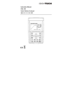
1
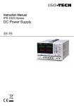
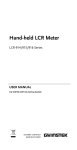
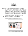
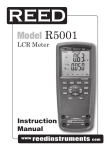
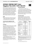
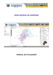
Instruction Manual
IDM 503 & 505
Digital Multimeters
IDM 505
IDM 503 / 505 English
SECTION 1 –SAFETY INFORMATION
Safety Information
Understand and follow operating instructions carefully.
Use the Instrument only as specified in this manual; otherwise, the protection provided
by the Instrument may be impaired.
WARNING
Identifies hazardous conditions and actions that could cause BODILY HARM or DEATH
CAUTION
Identifies conditions and actions that could DAMAGE the Instrument or equipment
under test
----------------
WARNING
xamine the instrument and probes before use. Do not use the instrument
E
if it is wet or damaged
When using test leads or probes, keep your fingers behind the finger guards.
Remove the test lead from the instrument before opening the battery cover
or instrument case.
Always use the correct terminals, switch position and range for measurements.
Never attempt a voltage measurement with the test leads inserted into the
“A”input terminals.
Verify the instrument is operating correctly by measuring a known voltage
before use. If in doubt, have the instrument serviced.
Do not apply more than the rated voltage, as marked on the instrument,
between terminals or between any terminal and earth ground.
Do not attempt a current measurement when the open-circuit voltage is above
the fuse protection rating.
Only replace a fuse with the correct type and rating as specified in this instruction
manual.
Use caution when measuring voltages above 30 Vac rms, 42 Vac peak or 60
Vdc. These voltages pose a shock hazard.
To avoid false readings that can lead to electric shock, replace the battery as
soon as the low battery indicator appears in the display.
Disconnect the circuit power and discharge all high-voltage capacitors before
making resistance, current, continuity, diode or capacitance measurements.
Do not use the instrument in a hazardous area or around explosive
gasses or vapours.
Wear suitable personal protective equipment when working around or near
hazardous live conductors which could be accessible.
2
IDM 503 / 505 English
CAUTION
• Disconnect the test leads from the test points before changing the position
of the function rotary switch.
• Never connect a source of voltage with the function rotary switch in the
“Ω”, “ ” , “°C” , “mA”, or “A” position.
• Do not expose the instrument to extremes in temperature or high humidity.
• Never set the instrument in the “Ω”, “ ” , “°C” , “mA”, or “A” position to measure
the voltage of a circuit, this could result in damage the instrument and the
equipment under test.
Symbols as marked on the instrument and instruction manual
Risk of electric shock
See instruction manual
DC measurement
Equipment protected by double or reinforced Insulation
Battery
Fuse
Earth
AC measurement
Conforms to EU directives
Dispose of in accordance with local regulations.
Unsafe Voltage
To alert you to the presence of a potentially hazardous voltage, when the Tester detects
a voltage ≧30 V or a voltage overload (OL) in V, mV . The
symbol is displayed and the
high voltage indicator is turned on.
Maintenance
Do not attempt to repair this instrument. It contains no user serviceable parts.
Repair or servicing should only be performed by qualified personnel.
3
IDM 503 / 505 English
Cleaning
Periodically wipe the case with a dry cloth and detergent.
Do not use abrasives or solvents.
SECTION 2 - METER DESCRIPTION
Instrument Description
Front Panel Illustration
1. LCD display : 4000/40000 counts for IDM503.
10000/100000 counts for IDM505.
2. Push-buttons.
3. Rotary switch to turn the power on or off and to select a function.
4. Input Terminal for “A” (current measurement)
5. Input Terminal for “V”, “Ω”, “ ”, Hz, and °C functions.
6. Common (ground reference) input terminal.
7. Input terminal for mA current measurement.
4
IDM 503 / 505 English
Making Basic Measurements
SECTION 3 – METER DESCRIPTION
Preparation and caution before measurement
Observe all warnings and cautions
When connecting the test leads to the device under test connect the common test lead
before connecting the live lead ; when removing the test leads remove the test live lead
before removing the common test lead.
The figures on the following pages show how to make basic measurements.
Measuring AC / DC Voltage
5
IDM 503 / 505 English
High Frequency Reject mode (HFR)
The HFR mode measures the voltage through a low pass filter to reject the high frequency.
The –3dB point of the low pass filter is 800 Hz. The HFR mode can be used when the
rotary switch is in the “V”, “mV” position. To use HFR mode, press the “HFR” button.
Measuring Resistance / Continuity / Diode Capacitance
Testing Continuity
6
IDM 503 / 505 English
Diode Testing
Measuring AC/DC Current
Press the blue button
to select the measuring function (AC/DC/AC+DC)
7
IDM 503 / 505 English
Measuring Frequency
Press the blue button
to select the measuring function. (Period/Duty)
Measuring Temperature °C / °F
Press the blue button
to select the measuring function. (°C / °F)
8
IDM 503 / 505 English
DIGIT:
Press the “DIGIT” button to select the display digit.
AUTO HOLD
In the Auto Hold function, the instrument holds the reading and the current reading
appears on the upper display. When the difference of the held value and the current value
is above 20 counts, the instrument beeps and holds the new value. To use the Auto Hold
mode, press the “A-HOLD” button.
9
IDM 503 / 505 English
Peak HOLD (ACV / ACA Only)
In the Peak Hold function, the instrument records the peak minimum value and the peak
maximum value; when the inputs go below the recorded peak minimum value or above the
recorded peak maximum value, the Instrument records the new value. To use the Peak
HOLD mode, press the “P-HOLD” button.
Sub-Functions navigation option
Sub-Functions item
Navigation : Select the Sub-function item.
Buttons
Navigation : Select the Sub-function item.
ENTER : Enter the Sub-function.
CANCEL : Exit the function.
10
IDM 503 / 505 English
STORE and RECALL
The store function records the input values to memory and recalls them from
memory after. Up to 1000 readings can be stored and recalled.
11
IDM 503 / 505 English
MAX / MIN / AVG
The MAX/MIN/AVG mode records the minimum and maximum input values. When the
inputs go below the record minimum value or above the record maximum value, the
Instrument records the new value. The MAX/MIN/AVG mode can also calculate the
average of the maximum value and the minimum value.
12
IDM 503 / 505 English
dB and dBm (ACV / ACmV only)
The decibel (dB) is a logarithmic unit of measurement that expresses the magnitude of a
physical quantity relative to a specified or implied reference level. The dB and dBm are
defined below.
dB = 20 log
VAC
1
dBm = 20 log
VAC
0.7746
13
IDM 503 / 505 English
Relative mode
In the relative mode, the instrument records the current input value as the reference and
appears on the upper display. For subsequent input values the instrument will calculate the
difference (Δ) between the reference value and the input value or the difference percent
(%) between the reference value and the input value.
14
IDM 503 / 505 English
SECTION 4 – SETUP OPTIONS
Press ▲ or ▼ changes the instrument setting.
Press “ENTER” to store the setting in memory.
Press ◄ or ► select the instrument setting item.
Press “CANCEL” to exit this function.
Beeper
Set the beeper to be ON or OFF.
Auto Power Off (APO)
Setup the auto power off (APO) time from 1 to 60 minutes or off.
15
IDM 503 / 505 English
Back Light Auto OFF
Setup the back light Auto OFF time from 1 to 60 minutes.
HAZARD
Set the hazardous voltage (≧60VDC or ≧30VAC) alarm beeper to ON or OFF.
RESET
Reset all setup values to the factory default.
16
IDM 503 / 505 English
LOG RATE
Setup the logging rate from 0.5 to 600 seconds.
DATALOG
The datalog mode records successive input values to memory and recalls them from
memory afterwards. Up to 20000 values can be recorded in the memory.
Connection to a PC
1. Turn on the meter, and use the USB cable to connect the meter with PC.
2. Put the software CD into the CD-ROM of PC, then install the program
and USB cable driver.
3. Run the program, the program will auto connect with the meter.
17
IDM 503 / 505 English
Auto Power Off
Wake up the instrument by switching the rotary switch or by pressing any button.
Auto Backlight
The backlight is automatically turned on in a dark environment.
AUTO BACKLIT
AUTO BACKLIT
Buzzer
The instrument buzzer beeps once for every valid key-press, and beeps twice for every
invalid key-press.
Power On Options
Press the following button while turning the Instrument on from the “OFF” position.
“CANCEL” button : Clear all stored data
“RANGE” button : Display LCD test frame
“FUNCTION” button : Default °C / °F reading
“HFR” button : Display firmware version
“A-HOLD” button : Disable AUTO BACKLIGHT
18
IDM 503 / 505 English
SECTION 5 – BATTERY AND FUSE REPLACEMENT
CAUTION
The following safety information must be observed to ensure maximum personal safety
during the operation of this instrument.
1. To avoid electric shock, disconnect the test leads before replacing the instrument
fuse or batteries.
2. When replacing the tester batteries, do not mix batteries of different types
or old and new batteries.
3. Check the battery polarity carefully when inserting the batteries.
4. Do not short-circuit used batteries, disassemble them, or throw them in a fire.
Doing so may cause the batteries to explode.
5. Dispose of the used batteries in accordance with local regulations.
Refer to the following figure to replace the fuse and the batteries :
19
IDM 503 / 505 English
CAUTION
Use only fuses with the following fuse rating:
Fuse rating :
440mA,1000V IR 10KA Fast acting fuse (size 35 x 10mm)
DMM-B-44/100 – 10,000A, 1000 VAC, unity power factor and
10,000A, 1000 VDC with time constant of 2.2ms
11A, 1000V IR 20KA Fast acting fuse (size 38 x 10mm)
DMM-B-11A – 20,000A, 1000 VAC, power factor ≦ 0.2; 20,000A,
1000 VDC, time constant ≧ 10ms. (size 38 x 10mm)
Replace the batteries as soon as the low batteries indicator “
false reading.
Replace with 4 x 1.5V AA alkaline batteries.
” appears, to avoid
SECTION 6 - SPECIFICATIONS
General Specifications
Maximum voltage applied to any terminal :
1000 V ac rms or dc.
Display : 4000/40000 counts for IDM503.
10000/100000 counts for IDM505.
Polarity Indication : Automatic, positive implied, negative indicated.
Overrange Indication : “OL”
Batteries Life : 100 hours typical
Low Batteries Indication : “ ” is displayed when the battery voltage drops below
the operating voltage.
Low battery voltage : Approx. 4.5V
Auto Power Off : Default 30 minutes.
Operating Ambient : Non-condensing ≦10°C,
11°C ~ 30°C (≦80% RH),
30°C ~ 40°C (≦75% RH),
40°C ~ 50°C (≦45%RH)
Storage Temperature : -20°C to 60°C , 0 to 80% RH (batteries not fitted)
Temperature Coefficient : 0.15 x (Spec.Accy) / °C, < 18°C or > 28°C .
Measure : Samples 3 times per second normal.
Altitude : 2000m
Safety : Complies with EN61010-1, UL61010-1,IEC 61010-1, CAT. IV 600V, CAT.III 1000V
20
IDM 503 / 505 English
Measurement
Category
Application
I
Measurements on circuits not directly connected to mains.
Examples include: Measurements on battery powered equipment
and specially protected (internal) mains-derived circuits.
II
Measurements on circuits directly connected to the low voltage
installation. Examples include: Household appliances, portable tools
and similar equipment.
III
Measurements performed in the building installation.
Examples include measurements on distribution boards, junction
boxes, socket-outlets and wiring and cables in the fixed installation.
IV
Measurements performed at the source of the low-voltage
installation. Examples include measurements on primary
overcurrent protection devices and electricity Instruments
Weight : (630g) including battery.
Dimensions (W x H x D) : 95mm x 207mm x 52mm with holster.
Accessories Supplied: 4 x 1.5V AA batteries (installed), Test lead set , type K
thermocouple bead sensor , PC software on CD ROM and user manual.
Power Requirements : 1.5V x 4 IEC LR6 or AA size.
Pollution degree : 2
EMC : EN 61326-1
Shock vibration : Sinusoidal vibration per MIL-T- 28800E (5 ~ 55 Hz, 3g maximum).
Drop Protection : 4 feet drop to hardwood on concrete floor.
Indoor use only.
21
IDM 503 / 505 English
Electrical Specifications
Accuracy is ±(% reading + number of digits) at 23°C ± 5°C < 80%RH.
(1) Voltage
IDM503
Range
Frequency
Accuracy
40.000mVDC
± (0.040% + 40d)
400.00mVDC
± (0.035% + 20d)
4.0000VDC
40.000VDC
400.00VDC
1000.0VDC
40.000mVAC
400.00mVAC
4.0000VAC
40.000VAC
400.00VAC
1000.0VAC
4.0000VAC
40.000VAC
–
± (0.03% + 20d)
40Hz ~ 65Hz
± (1.00% + 50d) [1]
66Hz ~ 1KHz
± (3.00% + 50d) [1]
1.01KHz ~ 3KHz
± (5.00% + 50d) [2]
40Hz ~ 45Hz
± (1.50% + 50d) [1]
46Hz ~ 65Hz
± (0.70% + 50d) [1]
66Hz ~ 1KHz
± (1.50% + 50d) [1] [4]
1.01KHz ~ 10KHz
± (3.00% + 50d) [2]
10.01KHz ~ 50KHz
± (5.00% + 50d) [3]
50.01KHz ~ 100KHz
± (10.0% + 50d) [3] [5]
[1] Below 5% of range, add 70 counts. Below 45Hz, < 50dgt rolling.
[2] Below 5% of range, add 150 counts.
[3] Below 5% of range, add 350 counts.
[4] At 1000.0VAC, the accuracy is ± (10.0% + 50d).
[5] At 40.000VAC, the accuracy is ± (15.0% + 50d).
22
IDM 503 / 505 English
IDM505
Range
Frequency
Accuracy
100.000mVDC
± (0.025% + 40d)
1000.00mVDC
± (0.020% + 20d)
10.0000VDC
100.000VDC
1000.00VDC
–
± (0.015% + 20d)
40Hz ~ 65Hz
± (0.70% + 50d) [1]
66Hz ~ 1KHz
± (1.50% + 50d) [1]
1.01KHz ~ 3KHz
± (3.00% + 50d) [2]
40Hz ~ 45Hz
± (1.00% + 50d) [1]
46Hz ~ 65Hz
± (0.40% + 50d) [1]
66Hz ~ 1KHz
± (1.00% + 50d) [1]
1.01KHz ~ 10KHz
± (2.00% + 50d) [1]
10.0000VAC
10.01KHz ~ 20KHz
± (3.00% + 50d) [2]
100.000VAC
20.01KHz ~ 50KHz
± (5.00% + 50d) [3]
50.01KHz ~ 100KHz
± (10.0% + 50d) [3] [4]
100.000mVAC
1000.00mVAC
10.0000VAC
100.000VAC
1000.00VAC
[1] Below 5% of range, add 70 counts. Below 45Hz, < 50dgt rolling.
[2] Below 5% of range, add 150 counts.[4] At 1000.0VAC,
the accuracy is ± (10.0% + 50d).
[3] Below 5% of range, add 350 counts.
[4] At 100.000VAC, the accuracy is ± (15.0% + 50d).
23
IDM 503 / 505 English
Input Protection :1000VDC or 1000VAC rms
Bandwidth : 40Hz ~ 100KHz
Minimum Resolution : 1µV in the 100mV range and the 40mV range.
Input Impedance : 10MΩ, <100pF
CMRR / NMRR : (Common Mode Rejection Ratio)
(Normal Mode Rejection Ratio)
VAC : CMRR > 60dB at DC, 50Hz / 60Hz
VDC : CMRR > 100dB at DC, 50Hz / 60Hz
NMRR > 50dB at DC, 50Hz / 60Hz
AC Conversion Type : AC conversions are ac-coupled, true rms responding,
calibrated to the sine wave input.
For non-sine wave add the following Crest Factor corrections :
For Crest Factor of 1.4 to 2.0, add 1.0% to accuracy.
For Crest Factor of 2.0 to 2.5, add 2.5% to accuracy.
For Crest Factor of 2.5 to 3.0, add 4.0% to accuracy.
AC+DC Accuracy : Add 1.0% to accuracy.
HFR Accuracy : Add 1.0% to accuracy at 40Hz ~ 400Hz.
The cut-off frequency of the High Frequency Reject : 800Hz (-3dB)
dB/dBm : ± 60dBm
Note : For best measurements, use the with REL Δ function to compensate for offsets.
(1) Voltage
IDM503
Range
40.000mADC
400.00mADC
4.0000mADC
10.000mADC
40.000AAC
400.00AAC
4.0000ADC
10.000AAC
Frequency
Accuracy
± (0.2% + 40d)
–
± (0.2% + 80d)
40Hz ~ 65Hz
± (0.8% + 80d) [1]
66Hz ~ 1KHz
± (3.0% + 80d) [1]
24
IDM 503 / 505 English
IDM505
Range
10.0000mADC
100.000mADC
Frequency
–
± (0.1% + 40d)
± (0.1% + 80d)
10.0000mADC
10.0000AAC
100.000AAC
10.0000AAC
Accuracy
40Hz ~ 65Hz
± (0.7% + 80d) [1]
66Hz ~ 1KHz
± (2.0% + 80d) [1]
[1] Below 5% of range, add 70 counts. Below 45Hz, < 50dgt rolling.
Input Protection : Protected by high energy fuse.
mA input: 440mA,1000V IR 10KA Fast acting fuse.
DMM-B-44/100 – 10,000A, 1000 VAC, unity power factor and
10,000A, 1000 VDC with time constant of 2.2ms
A input: 11A, 1000V IR 20KA Fast acting fuse for A input.
DMM-B-11A – 20,000A, 1000 VAC, power factor ≦ 0.2;
20,000A, 1000 VDC, time constant ≧ 10ms.
Bandwidth : 40Hz ~ 1KHz
Minimum Resolution :
1µA in the 40mA range for IDM503,
0.1µA in the 10mA range for IDM505.
Maximum Measuring Time :
3 minutes at “A” input, 10 minutes at “mA” input.
Rest time 20 minutes minimum.
AC Conversion Type : Conversion type and additional
specification are same as voltage.
(3) Peak HOLD
Specified accuracy ± (3.0% + 100d) up to 50000 count (full range).
25
IDM 503 / 505 English
(4) Resistance
IDM503
Range
Resolution
Accuracy
400.00Ω
0.01Ω
4.0000KΩ
0.1Ω
40.000KΩ
1Ω
400.00KΩ
10Ω
± (0.3% + 30d)
4.0000MΩ
100Ω
± (1.0% + 30d) [1]
40.00MΩ
10KΩ
± (1.5% + 30d) [1]
± (0.2% + 30d)
IDM505
Range
Resolution
Accuracy
1000.00Ω
0.01Ω
± (0.05% + 30d)
10.0000KΩ
0.1Ω
100.000KΩ
1Ω
1000.00KΩ
10Ω
± (0.3% + 30d)
10.0000MΩ
100Ω
± (1.0% + 30d) [1]
40.00MΩ
10KΩ
± (1.5% + 30d) [1]
± (0.025% + 30d)
[1] < 100dgt rolling.
Input Protection : 1000VDC or 1000VAC rms
Maximum Open Circuit Voltage : Approximate 2.5V
Maximum Test Current : Approximate 0.1mA
Note : For best measurements, use the with REL Δ function to compensate for offsets.
26
IDM 503 / 505 English
(5) Continuity Checks
IDM503
Range
Resolution
Accuracy
400.0Ω
0.1Ω
± (0.2% + 3d)
IDM505
Range
Resolution
Accuracy
1000.0Ω
0.1Ω
± (0.05% + 3d)
Input Protection : 1000VDC or 1000VAC rms
Maximum Open Circuit Voltage : Approximate 2.5V
Maximum Test Current : Approximate 0.1mA
Continuity Threshold : Approximate 50Ω
Continuity Indicator : 2kHz Tone Buzzer
(6) Diode Test
IDM503
Range
Resolution
Accuracy
2.000V
1mV
± (1.5% + 2d)
IDM505
Range
Resolution
Accuracy
0.400V ~ 0.800V
1mV
± (1.5% + 2d)
Input Protection : 1000VDC or 1000VAC rms
Maximum Open Circuit Voltage : Approximate ± 2.5V
Maximum Test Current : Approximate ± 0.5mA
27
IDM 503 / 505 English
(7) Capacitance
IDM503
Range
Resolution
Accuracy
Measuring Time
4.000nF
1pF
Unspecified
40.00nF
10pF
± (1.2% + 20d)
400.0nF
100pF
4.000µF
1nF
40.00µF
10nF
400.0µF
100nF
4.000mF
1µF
± (1.2% + 20d)
3.75sec
40.00mF
10µF
± (1.2% + 40d) [1]
7.5sec
0.7sec
± (0.9% + 2d)
IDM505
Range
Resolution
Accuracy
Measuring Time
4.000nF
1pF
Unspecified
40.00nF
10pF
± (1.2% + 20d)
400.0nF
100pF
4.000µF
1nF
40.00µF
10nF
400.0µF
100nF
4.000mF
1µF
± (1.2% + 20d)
3.75sec
40.00mF
10µF
± (1.2% + 40d) [1]
7.5sec
0.7sec
± (0.8% + 2d)
[1] < 50dgt rolling.
Input Protection : 1000VDC or 1000VAC rms
Note : For best measurements, use the with REL Δ function to compensate for offsets.
28
IDM 503 / 505 English
(8) Frequency Counter
IDM503/505
Range
Resolution
Accuracy
40.000Hz
0.001Hz
± (0.002% + 50d)
400.00Hz
0.01Hz
4.0000KHz
0.1Hz
40.000KHz
1Hz
400.00KHz
10Hz
4.0000MHz
100Hz
Sensitivity
1VP-P
± (0.002% + 10d)
5VP-P
Input Protection : 1000VDC or 1000VAC rms
Min Frequency : 5Hz
(9) Duty Factor
IDM503/505
Range
Resolution
Accuracy
Sensitivity
20.0% ~ 80.0%
0.1%
± (0.1% + 10d)
5VP-P
Input Protection : 1000VDC or 1000VAC rms
Sense Wave : Square Wave (5Hz ~ 10KHz)
(10) Temperature
IDM503/505
Range
-200.0°C ~ 10.0°C
10.1°C ~ 1200.0°C
-328.0°F ~ 50.0°F
50.1°F ~ 2192.0°F
Resolution
0.1°C
0.1°F
Accuracy
± (1.0% + 2°C)
± (1.0% + 1°C)
± (1.0% + 4°F)
± (1.0% + 2°F)
Input Protection : 1000VDC or 1000VAC rms
29
IDM 503 / 505 English
Africa
Iso-Tech
1 & 2 Indianapolis Street
Kyalami Business Park
Kyalami, Midrand, South Africa
Asia
Iso-Tech
460 Alexandra Road, #15-01A
PSA Building
Singapore 119963
Europe
Iso-Tech
PO Box 99
Corby
Northamptonshire
NN17 9RS
United Kingdom
Japan
Iso-Tech
West Tower (12th Floor)
Yokohama Business Park
134 Godocho, Hodogaya
Yokohama, Kanagawa 240-0005 Japan
USA
Iso-Tech
7410 Pebble Drive
Fort Worth
Texas 76118-6961
Canada
Iso-Tech
1701 Woodward Drive
Ste 108 Ottawa
Ontario K2C 0R4, Canada
South America
Iso-Tech
Av. Pdte. Eduardo Frei M. 6001-71
Centro Empresas El Cortijo
Conchali, Santiago, Chile
30