1
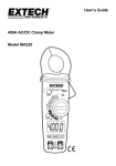
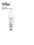
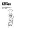
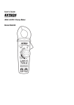
Owner's Manual
AC Clamp Meter
Model No.
82372
CAUTION: Read, understand and
follow Safety Rules and Operating
Instructions in this manual before
using this product.
• Safety
• Operation
• Maintenance
• Español
© Sears, Roebuck and Co., Hoffman Estates, IL 60179 U.S.A
www.craftsman.com
061906
TABLE OF CONTENTS
Warranty
Page 3
Safety Instructions
4
Safety Symbols
5
Control and Jacks
6
Symbols and Annunciators
6
Specifications
7
Operating Instructions
10
AC Current Measurements
10
AC Voltage Measurements
11
DC Voltage Measurements
11
Resistance Measurements
12
Continuity Measurements
12
Diode Testing
13
Auto Power Off
14
Data Hold
14
Max Hold
14
Auto/Manual Ranging
14
Maintenance
15
Battery Replacement
15
Troubleshooting
16
Service and Parts
16
2
ONE YEAR FULL WARRANTY
ONE YEAR FULL WARRANTY ON CRAFTSMAN AC CLAMP METER
If this CRAFTSMAN Clamp Meter fails to give complete satisfaction
within one year from the date of purchase, RETURN IT TO THE
NEAREST SEARS STORE OR OTHER CRAFTSMAN OUTLET IN THE
UNITED STATES, and Sears will replace it, free of charge.
This warranty gives you specific legal rights, and you may also have
other rights which vary from state to state.
Sears, Roebuck and Co., Dept. 817WA, Hoffman Estates, IL 60179
For Customer Assistance Call 9am - 5pm (ET)
Monday through Friday 1-888-326-1006
WARNING: USE EXTREME CAUTION IN THE USE OF THIS
DEVICE. Improper use of this device can result in injury or
death. Follow all safeguards suggested in this manual in addition
to the normal safety precautions used in working with electrical
circuits. DO NOT service this device if you are not qualified to do
so.
3
SAFETY INSTRUCTIONS
This meter has been designed for safe use, but must be operated
with caution. The rules listed below must be carefully followed for
safe operation.
1.
NEVER apply voltage or current to the meter that exceeds the
specified maximum:
Input Limits
Function
Maximum Input
V DC, V AC 600V DC/AC
A AC
400A AC
Resistance
250V DC/AC
Diode test
250V DC/AC
2.
USE EXTREME CAUTION when working with high voltages
3.
DO NOT measure voltage if the voltage on the "COM" input
jack exceeds 240V above earth ground
4.
DO NOT measure current of circuits whose voltage is greater
than 240V above earth ground
5.
NEVER connect the meter leads across a voltage source
while the function switch is in the resistance or diode mode.
Doing so can damage the meter
ALWAYS turn off the power and disconnect the test leads
before opening the doors to replace the fuse or batteries
6.
7.
NEVER operate the meter unless the back cover is in place
and fastened securely
4
SAFETY SYMBOLS
This symbol adjacent to another symbol,
terminal or operating device indicates that the
operator must refer to an explanation in the
Operating Instructions to avoid personal injury
or damage to the meter
WARNING
This WARNING symbol indicates a potentially
hazardous situation, which if not avoided, could
result in death or serious injury
CAUTION
This CAUTION symbol indicates a potentially
hazardous situation, which if not avoided, may
result in damage to the meter
MAX
600V
This symbol advises the user that the
terminal(s) so marked must not be connected to
a circuit point at which the voltage, with respect
to earth ground, exceeds (in this case) 600
VAC or VDC
This symbol adjacent to one or more terminals
identifies them as being associated with ranges
that may, in normal use, be subjected to
particularly hazardous voltages. For maximum
safety, the meter and its test leads should not
be handled when these terminals are energized
This symbol indicates that a device is protected
throughout by double insulation or reinforced
insulation
5
CONTROLS AND JACKS
1. Current clamp
1
2. MAX Hold button
3. Data Hold button
4. LCD display
6
5. COM input jack
2
6. Clamp Opening Trigger
7. Rotary Function Switch
7
8. V/ jack
3
9. Mode select button
10. Backlight button
4
9
11
11. Range Select button
5
SYMBOLS AND ANNUNCIATORS
AC
AC (alternating current)
DC
DC (direct currrent)
Minus sign
AUTO AutoRange mode
•)))
Audible Continuity
HOLD Data Hold mode
Low Battery icon
m
V
A
Diode test mode
milli
Volts
Amps
M
6
Mega
Ohms
10
8
SPECIFICATIONS
Function
Range
AC Current 2.000 AAC
20.00AAC
200.0 AAC
400.0 AAC
DC Voltage 200.0mV
2.000V
20.00V
200.0V
600V
AC Voltage 200.0mV
2.000V
20.00V
200.0V
600V
Resistance 200.0
2.000k
20.00k
200.0k
2.000k
20.00M
Accuracy
± (2.5% reading + 10 digits)
± (2.5% reading + 4 digits)
± (2.5% reading + 4 digits)
± (3.0% reading + 5 digits)
± (0.5% reading + 5 digits)
± (1.2% reading + 3 digits)
± (1.5% reading + 3 digits)
± (1.5% reading + 30 digits)
± (1.5% reading + 3 digits)
± (2.0% reading + 4 digits)
± (1.0% reading + 4 digits)
± (1.5% reading + 2 digits)
± (2.0% reading + 3 digits)
± (3.0% reading + 5 digits)
NOTE: Accuracy specifications consist of two elements:
• (% reading) This is the accuracy of the measurement circuit.
• (+ digits) This is the accuracy of the analog to digital converter
o
o
o
o
NOTE: Accuracy is stated at 65 F to 83 F (18 C to 28 C) and less
than 70% RH
7
Clamp size
Diode Test
Continuity Check
Opening 0.9" (23mm) approx.
Open circuit voltage <1.5V DC;
Test current 0.3mA (typical)
Audible signal <120;
Input Impedance
Test current < 1mA
7.8M (VDC and VAC)
Display
AC V bandwidth
AC A bandwidth
AC response
Operating Temperature
Storage Temperature
Operating Humidity
Storage Humidity
Operating Altitude
Over voltage
Battery
Auto OFF
Dimensions/Weight
Safety
3-1/2 digits (2000 counts) LCD
50Hz to 400Hz
50/60Hz
Averaging
o
o
41 to 104 F (5 to 40 C)
o
o
-4 to 140 F (-20 to 60 C)
Max 80% up to 87ºF (31ºC) decreasing
linearly to 50% at 104ºF (40ºC)
<80%
6560 ft. (2000 meters) maximum
Category III 600V
(2) 1.5V AAA Batteries
After 30 minutes of continuous use
7.87x1.97x1.38" (200x50x35mm) 0.44
lbs. (200g)
This meter is intended for indoor use
and protected, against the users, by
double insulation per EN61010-1 and
IEC61010-1 2nd Edition (2001) to CAT
III 600V; Pollution Degree 2. The meter
also meets UL 61010-1, Second Edition
(2004), CAN/CSA C22.2 No. 61010-1,
Second Edition (2004), and UL 61010B2-031, First Edition (2003)
8
UL LISTED
The UL mark does not indicate that this product has been
evaluated for the accuracy of its readings
PER IEC1010 OVERVOLTAGE INSTALLATION CATEGORY
OVERVOLTAGE CATEGORY I
Equipment of OVERVOLTAGE CATEGORY I is equipment for
connection to circuits in which measures are taken to limit the
transient overvoltages to an appropriate low level. Note –
Examples include protected electronic circuits.
OVERVOLTAGE CATEGORY II
Equipment of OVERVOLTAGE CATEGORY II is energyconsuming equipment to be supplied from the fixed installation.
Note – Examples include household, office, and laboratory
appliances.
OVERVOLTAGE CATEGORY III
Equipment of OVERVOLTAGE CATEGORY III is equipment in
fixed installations.
Note – Examples include switches in the fixed installation and
some equipment for industrial use with permanent connection to
the fixed installation.
OVERVOLTAGE CATEGORY IV
Equipment of OVERVOLTAGE CATEGORY IV is for use at the
origin of the installation.
Note – Examples include electricity meters and primary overcurrent protection equipment
9
OPERATING INSTRUCTIONS
Notice: Read and understand all WARNING and CAUTION
statements listed in the safety section of this operation manual
prior to using this meter. Set the function select switch to the
OFF position when the meter is not in use.
NOTES:
1. ALWAYS turn the rotary function switch to the OFF position
when the meter is not in use
2. If “OL” appears in the display during a measurement, the value
exceeds the range you have selected. Change to a higher
range
AC CURRENT MEASUREMENTS
WARNING: Disconnect the test leads from the meter before
making current clamp measurements.
1.
Set the Function switch to the 400AAC,
200AAC, 20AAC or 2AAC range. If the
range of the measured current is not
known, select the higher range first then
move to the lower range if necessary.
Yes
2. Press the trigger to open jaw. Fully
enclose one conductor to be measured.
Note: Do not put more than one wire
inside the current clamp.
3. The clamp meter LCD will display the reading.
No
10
DC/AC VOLTAGE MEASUREMENTS
WARNING: Risk of Electrocution. The probe tips may not be
long enough to contact the live parts inside some 240VAC
outlets for appliances because the contacts are recessed deep
in the outlets. As a result, the reading may show 0 volts when
the outlet actually has voltage on it. Make sure the probe tips
are touching the metal contacts inside the outlet before
assuming that no voltage is present.
CAUTION: Do not measure DC or AC voltages if a motor on
the circuit is being switched ON or OFF. Large voltage surges
may occur that can damage the meter.
1. Set the rotary function switch to the
VAC position for AC Voltage or VDC
position for DC Voltage.
2. Insert the black test lead banana plug
into the negative (COM) jack and the
red test lead banana plug into the
positive (V/) jack
3. Connect the test leads to the circuit
under test
4. Read the voltage on the display. The
display will indicate the proper
decimal point and value. For DC
voltage, if the polarity is reversed, the
display will show (-) minus before the
value
11
V
RESISTANCE MEASUREMENTS
WARNING: To avoid electric shock, disconnect all power to the
unit under test, remove the batteries, unplug the line cords and
discharge all capacitors before taking any resistance
measurements.
1.
2.
3.
4.
Set the function switch to the •))) position.
Insert the black test lead banana plug
into the negative (COM) jack and the
red test lead banana plug into the
positive (V/) jack
Touch the test probe tips across the
circuit or part under test. It is best to
disconnect one side of the part under
test so the rest of the circuit will not
interfere with the resistance reading
Read the resistance in the display
Ohms
CONTINUITY CHECK
WARNING: To avoid electric shock, never measure continuity
on circuits or wires that have voltage on them.
1.
2.
3.
4.
5.
Set the function switch to the •))) position.
Push the mode button to indicate •))) on the display.
Insert the black lead banana plug into the negative (COM) jack
Insert the red test lead banana plug into the positive (V) jack.
Touch the test probe tips to the circuit or wire you wish to
check.
If the resistance is less than approximately 120, the audible
signal will sound. If the circuit is open, the display will indicate
“OL.”.
12
DIODE TEST
WARNING: To avoid electric shock, do not test any diode that
has voltage on it.
1. Turn the rotary switch to the •))) position.
2. Insert the black test lead banana plug into the negative (COM)
jack and the red test lead banana plug into the positive (V)
jack.
3. Push the mode button to indicate
on the display.
4. Touch the test probes to the diode under test. Typically for a
normal diode, forward voltage will indicate 0.4V to 0.7V.
Reverse voltage will indicate “OL”. Shorted devices will
indicate near 0V and an open device will indicate “OL” in both
polarities.
13
AUTO POWER OFF
To extend the battery life, the meter will enter the sleep mode after
30 minutes of continuous use. Turn the function switch to the OFF
position to shut the meter OFF and then to the needed function to
resume operation.
DATA HOLD
To freeze the LCD meter reading, press the HOLD button. While
data hold is active, the HOLD display icon appears on the LCD.
Press the HOLD button again to return to normal operation.
MAX Hold
To hold the highest reading on the LCD, press the MAX button.
The max hold button is located on the left side of the meter (top
button). While data hold is active, the MAX display icon appears on
the LCD. The meter reading will not change as readings change,
rather it will only display the highest reading encountered since the
max hold button was pressed. Press the max hold button again to
return to normal operation.
AUTO/MANUAL RANGING
The meter turns on in Autoranging mode. Press the RANGE button
to enter manual ranging. Each press of the range button will step
to the next range as indicated by the units and decimal point
location. Press and hold the RANGE button for two seconds to
return to Autoranging mode.
Note: Manual ranging does not function in AC Current or Diode
and Continuity check functions.
14
MAINTENANCE
WARNING: To avoid electric shock, do not operate your meter
until all covers are in place and fastened securely.
This meter is designed to provide years of dependable service, if
the following care instructions are performed:
1. KEEP THE METER DRY. If it gets wet, wipe it off.
2. USE AND STORE THE METER IN NORMAL
TEMPERATURES. Temperature extremes can shorten the life
of the electronic parts and distort or melt plastic parts.
3. HANDLE THE METER GENTLY AND CAREFULLY. Dropping
it can damage the electronic parts or the case.
4. KEEP THE METER CLEAN. Wipe the case occasionally with a
damp cloth. DO NOT use chemicals, cleaning solvents, or
detergents.
REPLACING THE BATTERIES
WARNING: To avoid electric shock, disconnect the test leads
from any source of voltage before removing the battery door.
1. When the batteries become exhausted or drop below the
operating voltage, the low battery indicator will appear in the
LCD display. The batteries should then be replaced.
2. Disconnect the test leads from the meter.
3. Open the battery door by removing the rear screws using a
Phillips head screwdriver.
4. Insert the batteries into battery holder.
5. Put the battery door back in place. Secure with the screws.
6. Dispose of the old batteries properly.
WARNING: To avoid electric shock, do not operate the meter
until the battery door is in place and fastened securely.
NOTE: If your meter does not work properly, check the battery
ensuring that it is still good and properly inserted.
15
TROUBLESHOOTING
There may be times when your meter does not operate properly.
When this occurs, check the following:
Meter Does Not Operate
1. Review all the instructions in this manual.
2. Check to be sure the battery is properly installed.
3. Check to be sure the battery is good.
4. If the battery is good and the meter still does not operate, check
to be sure that both ends of the fuse are properly installed.
If You Need Assistance Understanding How the Meter Works
1.
2.
Purchase the instructional book Multitesters and Their Use for
Electrical Testing (Item No. 82303) at your local Sears store.
Call our Customer Service Line 1-888-326-1006.
SERVICE AND PARTS
Item Number
82398
82372-DB
82372-CS
Description
Set of black and red Test Leads
Replacement battery door
Rear cover screws
For replacement parts shipped directly to your home
Call Monday through Friday, 9 AM – 5 PM Eastern Time
1-888-326-1006
16