1
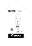
SEFRAM 7334/7335
MULTIMÈTRES NUMÉRIQUES TRMS AC+DC
TRMS AC+DC DIGITAL MULTIMETERS
Manuel d’utilisation
User’s Manual
M7334/7335 M00
Warning
Safety
sheet
sheet
Safety
Warning
..........
..........
..........
........
.........
..........
..........
........
.........
A lire avant toute utilisation
Prescriptions de sécurité
Ce manuel contient toutes les précautions qui doivent
impérativement être respectées afin de pouvoir utiliser cet
appareil en toute sécurité pour l’utilisateur.
Danger
Il s’agit d’identifier les conditions d’utilisation qui pourraient
entraîner de graves dangers pour l’utilisateur.
Attention
Il s’agit d’identifier les conditions d’utilisation qui pourraient
entraîner des dommages techniques pour l’appareil.
Attention
˙ Lors de l’utilisation des cordons de mesure, toujours
conserver les doigts en amont de l’anneau de protection.
˙ Toujours déconnecter les cordons avant de procéder au
remplacement de la pile ou avant d’ouvrir le multimètre.
˙ Toujours utiliser le multimètre dans les limites spécifier dans
ce manuel, sinon les protections pourraient être
endommagées et la sécurité de l’utilisateur compromise.
˙ Toujours vérifier que les douilles utilisées correspondent bien
à la position du commutateur rotatif.
˙ Vérifier périodiquement le multimètre sur une tension
connue. En cas de doute, le faire vérifier ou réparer par du
personnel compétent.
˙ Ne jamais appliquer plus que la tension maximale spécifiée
entre les bornes ou entre n’importe quelle borne et la terre.
˙ Remplacer le fusible par un type strictement équivalent à
celui spécifié.
˙ Manipuler avec précaution les tensions supérieures à 30 Vac
eff., 42 Vac crête, ou 60 Vdc. Ces tensions peuvent
provoquer des chocs électriques.
˙ Pour éviter des erreurs de mesure et leurs conséquences, il
est important de remplacer la pile dès que le symbole pile
faible apparait.
˙ Avant toute mesure de capacité ou de résistance, s’assurer
que les dispositifs sont hors tension et déchargés.
˙ Ne jamais utiliser l’appareil en atmosphère explosive.
˙ Afin de réduire les risques de chocs électriques, ne pas
utiliser l’appareil s’il est mouillé ou humide.
1
ATTENTION
˙ Toujours déconnecter les cordons de l’application avant de
tourner le commutateur rotatif.
˙ Ne jamais appliquer une tension en position Ω, test diode,
°C ,mA, A.
˙ Ne jamais exposer l’appareil à des températures extrêmes
ou une trop forte humidité.
Symboles utilizes dans ce manuel ou sur l’appareil
Risque de choc électrique
Se reporter au manuel d’utilisation
Mesures en continu (DC)
Double isolement
<
Pile
Fusible
Terre
Mesures en alternative (AC)
Conformité CE
Ne pas jeter ce produit. A recycler
Tensions dangereuses
Pour prévenir l’utilisateur de présence de tension dangereuse,
lorsque le multimètre détecte une tension ≧30 V ou un
dépassement de gamme (OL) en V, mV, le symbole haute
tension est affiché.
Maintenance
Ne pas tenter de réparer le multimètre. La réparation ne doit se
faire que par du personnel qualifié. Contactez votre distributeur.
Nettoyage
Nettoyez périodiquement l’appareil avec un chiffon doux et
humide.
Ne jamais utiliser de solvant ou de matériaux abrasifs.
2
Introduction
Description du multimètre
Face avant
1. Afficheur LCD : 6000 points
2. Touches de fonctions
3. Commutateur rotatif, avec M/A de l’appareil.
4. Borne d’entrée A.
5. Borne d’entrée V,Ω, &, °C
6. Borne COM (point froid des mesures)
7. Borne d’entrée mA.
1.Afficheur
2.Touches
3.Commutateur rotatif
4.Entree A
5.Entree V ,Ω, &,°C
6.Entree COM
7.Entree mA
3
Caractéristiques
•
•
•
•
•
•
Affichage 6000 points.
•
•
•
•
•
•
•
•
•
•
Fonction Data Hold
Bargraphe 62 segments.
LCD panoramique avec rétro-éclairage
Mesures TRMS AC+DC
Précision de base de 0.08% en V DC
Détection automatique de tension AC ou DC
(sur position Auto-V LoZ)
• Détecteur de tension sans contact intégré
Fonction Peak Hold (1ms) sur 7335
Fonction Min/ Max
Fréquencemètre en V AC
Mesure de capacité
Température (sur 7335)
Indication de pile faible
Arrêt automatique (20 minutes)
résistance au choc (chute de 1m)
Sécurité: CAT.IV 600V/CAT III 1000V
Déballage et inspection
A la réception de votre instrument, le carton d’emballage doit
contenir :
1. Le multimètre 7334 ou 7335
2. Un jeu de cordons de sécurité (1 noir, 1 rouge)
3. Une sonde de temperature (7335)
4. Un manuel d’utilisation
5. Une gaine de protection montée sur l’appareil
6. Les piles installées dans l’appareil
4
Mise en œuvre de mesures simples
Mise en garde avant d’utiliser le multimètre
Il est impératif d’observer les prescriptions de sécurité
Attention
Lors du branchement du multimètre à l’application, il est
impératif de toujours brancher le point froid (COM) en premier,
puis de brancher le point chaud. Procéder en ordre inverse pour
vous déconnecter de l’application.
Les schémas qui suivent montrent comment se brancher pour
réaliser des mesures avec votre appareil.
Mesure de tensions AC / DC
Utilisez le commutateur rotatif et la touche fonction (bleue).
5
Mesure de courant AC/DC
Déconnectez
Utilisez le commutateur rotatif et la touche fonction (bleue).
Mesure de Fréquence
Appuyez sur la touche
fonction (bleue) pour
sélectionner le type de
mesure
Utilisez le commutateur rotatif et la touche fonction (bleue).
6
Mesure de Résistance/Capacité
Résistance
Capacité
Résistance
Capacité
Utilisez le commutateur rotatif et la touche fonction (bleue).
Mesure de Continuité / Test Diode
Utilisez le commutateur rotatif et la touche fonction (bleue).
7
Mesure de température °C / °F (sur 7335 uniquement)
Appuyez
Sonde de type K
Utilisez le commutateur rotatif et la touche bleue pour changer
d’unité (°C / °F).
8
Utilisation des fonctions
Les touches Fonction (touche bleue)
Appuyez
AC
Position du
commutateur
Fonction
ac+dc
Utiliser la touche Fonction (bleue) pour changer de type de
mesure ou d’affichage, en restant sur la même position du
commutateur
Touche RANGE
Appuyer sur la touche range »
pendant plus d’une seconde pour
revenir en.
9
MIN/MAX
Mesure courante
Mesure Max.
Appuyez sur “MinMax”
pendant plus d’une
seconde pour sortir de
la fonction
Mesure Min.
La fonction MAX/MIN permet d’enregistrer la valeur Min et Max
d’une série de valeurs. Appuyer sur hold pour arrêter
l’enregistrement.
Fonction Peak HOLD (7335 uniquement)
Mesure courante
Press
2 sec.
Mesure Max.
Appuyez sur “MinMax”
pendant plus d’une
seconde pour sortir de
la fonction
Mesure Min.
Dans le mode Peak Hold, le multimètre enregistre les crêtes
min et les crêtes max du signal. Si une valeur crête supérieure
(en absolu) est mesurée, elle remplace la valeur précédente.
Appuyer sur Hold pour arrêter l’enregistrement.
10
Fonction Smart HOLD
Le multimètre émettra un bip sonore si la valeur mesurée est
supéieure de 50 digits à celle affichée. (n’est pas possible en
AC+DC tension ou courant).
Fonction VoltSense
Maintenir la touche VoltSense enfoncée pour utiliser cette
fonction de détecteur de tension.
Attention - Danger
Le nombre de trait affichés sur le LCD indique la force du champ
électrique.
S’il n’y a pas de trait affiché, cela ne veut pas dire qu’il n’y a pas
de tension présente. Ne jamais se servir de la fonction Voltsense
comme élément de test qui puisse mettre en jeu la sécurité de
l’utilisateur.
11
Rétro-éclairage
Appuyer sur le touche de retro-éclairage pour active/désactiver
cette fonction.
Arrêt automatique
Après 20 minutes
L’appareil peut être remis en marche par un appui sur une
touche ou un changement de position du commutateur rotatif.
Inhiber l’arrêt automatique
1
2
Pour cela, il suffit de mettre en marche le multimètre tout en
appuyant sur la touche bleue.
12
Test du LCD
1
2
Il faut mettre en marche l’appareil tout en appuyant sur la
touché Smart Hold. Tous les segments du LCD restent
allumés.
13
Remplacement des fusibles
Boitier arrière
Couvercle pile
Fusible 440mA(1000V)
Fusible 11A (1000V)
Attention - Danger
Il est impératif de débrancher les cordons de mesure et
d’arrêter l’appareil avant d’ouvrir le couvercle arrière
Remplacement de la pile
Dès que le symbole pile est affiché, il faut procéder au
remplacement de celle-ci..
Se référer à la figure ci-dessous pour remplacer la pile. Bien
respecter la polarité.
Vis
Couvercle pile
Pile 9V
Attention - Danger
Il est impératif de débrancher les cordons de mesure et
d’arrêter l’appareil avant d’ouvrir le couvercle arrière
14
Spécifications
Spécifications Générales
Tension maximale admissible (quelle que soit la borne) :
1000 Vac eff. ou 1000 V DC
Mesures selon EN 61557 :
IEC61557-1, IEC61557-2, IEC61557-4, IEC61557-10
Masse : 460g (avec pile)
Dimensions (W x H x D) : 94mm x190mm x 48mm avec gaine.
Accessoires livrés avec:
pile (installée), jeu de cordons de mesure et manuel.
(Les cordons de mesure fournis avec le produit sont destinés à
être utilisés avec ce produit)
Degré de pollution: 2 1000 Vdc.
Affichage : 6000 points.
Polarité : Automatique, signe moins pour la polarité négative.
Indication de dépassement : affichage de “OL »
Autonomie : 150heures avec pile alcaline (sans rétro-éclairage)
Indication de pile faible : symbole pile clignotant sur le LCD
Alimentation : pile 9V (6F22)
Arrêt automatique: après 20 minutes.
Température d’utilisation : -10 à10°C
10°C à 30°C (≦80% HR),
30°C à 40°C (≦75% HR),
40°C à 50°C (≦45% HR)
Température de stockage :
-20°C à 60°C , 0 à 80% R.H. (pile enlevée)
Coefficient de température:
0.15 x (précision) / °C, pour t < 18°C ou t > 28°C .
Cadence de mesure : 3 mes/s
Altitude d’utilisation: jusqu’à 2000m
Sécurité : EN61010-1, UL61010-1,IEC 61010-1,
CAT.IV. 600V, CAT.III. 1000V
CEM : EN 61326-1
Vibration : sinus, selon MIL-PRF- 28800F (5 ~ 55 Hz, 3g max.)
Protection aux chutes : chute de 1m sur sol en béton
Utilisation: à l’intérieu
15
Spécifications Electriques
Précision exprimée en ±(% lecture + nombre de digits) à
23°C ± 5°C < 80% HR.
(1) Tension
Gamme
Résolution
Précision - 7334 Précision - 7335
60.00mVDC
0.01mV
600.0mVDC
0.1mV
± (0.1% + 2d)
± (0.08% + 2d)
6.000VDC
0.001V
± (0.09% + 2d)
± (0.08% + 2d)
60.00VDC
0.01V
± (0.09% + 2d)
± (0.08% + 2d)
600.0VDC
0.1V
± (0.09% + 2d)
± (0.08% + 2d)
1000VDC
1V
± (0.09% + 2d)
± (0.08% + 2d)
60.0mVAC
0.01mV
600.0mVAC
0.1mV
± (1.5% + 5d)
± (1.20% + 5d)
6.000VAC
0.001V
± (1.0% + 3d)
± (0.80% + 5d)
60.00VAC
0.01V
± (1.0% + 3d)
± (0.80% + 5d)
600.0VAC
0.1V
± (1.0% + 3d)
± (0.80% + 5d)
1000VAC
1V
± (1.0% + 3d)
± (0.80% + 5d)
± (0.08% + 10d)
± (1.20% + 5d)
Protection d’entrée : 1000VDC ou 1000VAC eff.
Réponse en fréquence : 50Hz à 1KHz
Impédance d’entrée : 10MΩ, <100pF
Type de conversion AC : TRMS, Couplage AC
Pour des signaux non sinusoïdaux, il faut rajouter:
Facteur de crête de 1.4 à 2.0 : ajouter 1.0% à la précision
Facteur de crête de 2.0 à 2.5, ajouter 2.5% à la précision
Facteur de crête de 2.5 à 3.0, ajouter 4.0% à la précision
16
(2) Auto-V (Tensions automatiques, basse impédance)
Gamme
Résolution
600.0VDC
0.1V
1000VDC
1V
600.0VAC
0.1V
1000VAC
1V
Précision - 7334 Précision - 7335
± (1.0% + 3d)
± (0.80% + 3d)
Protection d’entrée : 1000VDC ou 1000VAC eff.
Réponse en fréquence : 50Hz à 1KHz
Impédance d’entrée : environ 3kΩ.
Type de conversion AC : idem à celles du (1) Tension
(3) Courant
Gamme
Résolution
Précision - 7334 Précision - 7335
60.00mADC
0.01mA
± (1.0% + 3d)
± (0.8% + 3d)
600.0mADC
0.1mA
± (1.0% + 3d)
± (0.8% + 3d)
6.000ADC
0.001A
± (1.0% + 3d)
± (0.8% + 3d)
10.00ADC
0.01A
± (1.0% + 3d)
± (0.8% + 3d)
60.00mAAC
0.01mA
± (1.5% + 3d)
± (1.2% + 3d)
600.0mAAC
0.1mA
± (1.5% + 3d)
± (1.2% + 3d)
6.000AAC
0.001A
± (1.5% + 3d)
± (1.2% + 3d)
10.00AAC
0.01A
± (1.5% + 3d)
± (1.2% + 3d)
Protection d’entrée : avec fusible haut pouvoir de coupure.
Fusible 440mA, 1000V AC/DC 10KA sur l’entrée mA
Fusible 11A, 1000V AC/DC 20KA sur l’entrée A
Durée maximale de mesure :
3 minutes sur l’entrée A, 10 minutes sur l’entrée mA.
Avec un temps d’arrêt de 20 minutes.
Type de conversion AC : idem à celles du (1)
Réponse en fréquence : 50Hz à 1KHz
17
(4) Peak Hold (sur 7335 uniquement) : Précision de ±150d.
(5) Résistance
Gamme
Résolution
Précision
600.0Ω
0.1Ω
± (0.8% + 5d)
6.000KΩ
0.001KΩ
60.00KΩ
0.01KΩ
600.0KΩ
0.1KΩ
6.000MΩ
0.001MΩ
40.00MΩ*
0.01MΩ
± (0.8% + 2d)
± (1.0% + 5d)
Protection d’entrée : 1000VDC ou 1000VAC eff.
Tension en circuit ouvert :
environ. 2.5V sur les gammes 600Ω & 6kΩ
environ. 0.6V sur les autres gammes
Courant de test : environ 0.1mA (max.)
* il peut être constaté une instabilité de ±50 digits sur les
valeurs mesurées > 10.00MΩ.
(6) Test de Continuité
Gamme
Résolution
Précision
600.0Ω
0.1Ω
± (0.8% + 5d)
Protection d’entrée : 1000VDC ou 1000VAC eff.
Tension en circuit ouvert : environ. 2.5V
Courant de test : environ 0.1mA (max.)
Seuil pour le buzzer: R < 30Ω - buzzer actif
R > 100Ω - buzzer inactif
Signal sonore : buzzer, 2.7KHz
(7) Test Diode
Gamme
Résolution
Précision
2.000V
1mV
± (1.5% + 2d)
Protection d’entrée : 1000VDC ou 1000VAC eff.
Tension en circuit ouvert : environ. 2.5V
Courant de test : environ 0.4mA (max.)
18
(8) Mesure de capacité
Gamme
Résolution
1.000μF
0.001μF
10.00μF
0.01μF
100.0μF
0.1μF
1.000mF
0.001mF
10.00mF
0.01mF
Précision
± (1.2% + 2d)
Protection d’entrée : 1000VDC ou 1000VAC eff.
Temps de mesure : 0.7 sec de 1nF à 1mF
3 sec de 1mF à 10mF
(9) Fréquencemètre
Gamme
Résolution
100.00 Hz
0.01 Hz
1000.0 Hz
0.1 Hz
10.000 KHz
0.001 KHz
100.00 KHz
0.01 KHz
Précision
± (0.1% + 2d)
Protection d’entrée : 1000VDC ou 1000VAC eff.
Fréquence minimum :1Hz
Sensibilité:> 5.0Vc-c (tension AC de 1HZ à 10kHz).
> 10Vc-c (tension AC de 10kHZ à 100kHz).
> 2mAc-c(courant AC, entrée mA).
> 0.2Ac-c (courant AC, entrée A).
(10) Température (sur 7335 uniquement)
Gamme
Résolution
Précision
-40.0°C ~ 400°C
0.1°C
± (1.0% + 10d)
-40.0°F ~ 752°F
0.1°F
± (1.0% + 18d)
Protection d’entrée : 1000VDC ou 1000VAC eff.
* n’inclut pas la précision du thermocouple
* la précision suppose que la température du multimètre ne
varie pas plus de ± 1°C. Pour une variation de ± 5°C, la
précision est atteinte après 2 heures de stabilisation.
19
Remarque : la valeur TRMS AC+DC peut dépasser la
gamme en cours, puisque la tension AC vient se superposer à
la tension continue.
(11) Tension AC+DC
Gamme
Résolution
6.000V
0.001V
60.00V
0.01V
600.0V
0.1V
1000V
1V
Précision - 7334 Précision - 7335
± (2.5% + 5d)
± (2% + 5d)
Autres spécifications identiques à celles des tensions - voir (1).
(12) mV AC+DC
Gamme
Résolution
60.00mV
0.01mV
600.0mV
0.1mV
Précision - 7334 Précision - 7335
± (2% + 10d)
± (2.5% + 5d)
Autres spécifications identiques à celles des tensions - voir (1).
(13) Courant mA AC+DC
Gamme
Résolution
60.00mA
0.01mA
600.0mA
0.1mA
Précision - 7334 Précision - 7335
± (2.5% + 5d)
± (2% + 5d)
Autres spécifications identiques à celles des courants - voir (3).
(14) Courant A AC+DC
Gamme
Résolution
6.000A
0.001A
10.00A
0.01A
Précision - 7334 Précision - 7335
± (2.5% + 5d)
± (2% + 5d)
Autres spécifications identiques à celles des courants - voir (3).
20
Warning
Warning
Safety
Safetysheet
sheet
..........
..........
..........
........
.........
..........
..........
........
.........
Read First
Safety Information
Understand and follow operating instructions carefully.
Use the meter only as specified in this manual; otherwise,
the protection provided by the meter may be impaired.
WARNING
Identifies hazardous conditions and actions that could cause
BODILY HARM or DEATH
CAUTION
Identifies conditions and actions that could DAMAGE the meter
or equipment under test
WARNING
˙ When using test leads or probes, keep your fingers behind
the finger guards.
˙ Remove test lead from Meter before opening the battery
door or Meter case.
˙ Use the Meter only as specified in this manual or the protection by the Meter might be impaired.
˙Always use proper terminals, switch position, and range for
measurements.
˙Verify the Meter’s operation by measuring a known voltage.
If in doubt, have the Meter serviced.
˙ Do not apply more than the rated voltage, as marked on
Meter, between terminals or between any terminal and
earth ground.
˙ Only replace the blown fuse with the proper rating as specified in this manual.
˙ Use caution with voltages above 30 Vac rms, 42 Vac peak,
or 60 Vdc. These voltages pose a shock hazard.
˙ To avoid false readings that can lead to electric shock and
injury, replace battery as soon as low battery indicator.
˙ Disconnect circuit power and discharge all high-voltage
capacitors before testing resistance, continuity, diodes, or
capacitance.
˙ Do not use Meter around explosive gas or vapor.
˙To reduce the risk of fire or electric shock do not expose this
product to rain or moisture.
1
CAUTION
˙ Disconnect the test leads from the test points before changing the position of the function rotary switch.
˙ Do not expose Meter to extremes in temperature or high
humidity.
˙ Never set the meter in Ω,,°C ,mA, A function to measure
the voltage of a power supply circuit in equipment that could
result in damage the meter and the equipment under test.
Symbols as marked on the Meter and Instruction
manual
Risk of electric shock
See instruction manual
DC measurement
Equipment protected by double or reinforced insulation
<
Battery
Fuse
Earth
AC measurement
Conforms to EU directives
Do not discard this product or throw away.
Unsafe Voltage
To alert you to the presence of a potentially hazardous voltage,
when the Tester detects a voltage ≧30 V or a voltage
overload (OL) in V, mV . The ”“ symbol is displayed.
Maintenance
Do not attempt to repair this Meter. It contains no userserviceable parts. Repair or servicing should only be performed by
qualified personnel.
Cleaning
Periodically wipe the case with a dry cloth and detergent.
Do not use abrasives or solvents.
2
Introduction
The Meter Description
Front Panel Illustration
1. LCD display : 6000 counts
2. Push-buttons.
3. Rotary switch for turn the Power On / Off and select the
function.
4. Input Terminal for A.
5. Input Terminal for V,Ω, &, °C functions.
6. Common (Ground reference) Input Terminal.
7. Input Terminal for mA.
1.Display
2.Buttons
3.Rotary switch
4.A input
5.V,
,
,
input
6.Common input
7.mA input
3
Feature
• 6000 count digital display.
• 62 segment bar graph .
• Extra Large scale display and while backlit
• True RMS
• 0.08% basic DCV accuracy
• Automatic AC/DC Voltage detect with low impedance
(Auto-V LoZ)
• VoltSense (Non-Contact Voltage detect)
• Smart Data Hold
• Peak Hold (1ms) (for 7335 only)
• Min/ Max function
• AC+DC function
• Frequency Counter on AC mode
• Capacitance Measurement
• Temperature ( for 7335 only)
• Low battery indicator with segments
• Auto Power Off (20 minutes)
• Shock proof from 4 feet drops
• CAT.IV 600V/CAT. Ⅲ 1000V Safety standard
Unpacking and Inspection
Upon removing your new Digital Multimeter from its packing,
you should have the following items.
1. SEFRAM 7337/7335 Series Digital Multimeter.
2. Test leads. set (one black, one red)
3. Temperature Probe
4. User Manual
5. Protective Holster
6. Battery Installed
4
Making Basic Measurements
Preparation and Caution Before Measurement
: Observe the rules of Warnings and Cautions
The figures on the following pages show how to make basic
measurements.
Caution
When connecting the test leads to the DUT (Device Under
Test) connect the common test leads before connecting the
live test leads ; when removing the test leads, remove the
live test leads before removing the common test leads.
Measuring AC / DC Voltage
Dial the switch and press the Function button to select the
measuring function.
5
Measuring AC/DC Current
Disconnect
Dial the switch and press the Function button to select the
measuring function.
Measuring Frequency
Press the function
button to select the
measuring function.
Dial the switch and press the Function button to select the
measuring function
6
Measuring Resistance/Capacitance
Resistance
Capacitance
Resistance
Capacitance
Dial the switch and press the Function button to select the
measuring function.
Measuring Continuity / Diode
Dial the switch and press the Function button to select the
measuring function.
7
Measuring Temperature °C / °F (for 7335 only)
Dial the switch and press the Function button to select the
measuring function. (°C / °F)
8
Using The Function
Function Button
Press
AC
Switch
Position
Function
ac+dc
Press the Function button to change the function on the same
switch position.
RANGE Button
Press
button > 1sec to Auto Range Mode.
9
MIN/MAX
Present Reading
Max. Reading
Press
button over 1 sec.
to exit this function
Min. Reading
The MAX/MIN mode records the min. and max. input values.
When the input goes below the recorded min. value or above
the recorded max. value, the meter records the new value .
Press Hold button to pause the recording.
Peak HOLD (for 99Ⅲonly)
Present Reading
Press
2 sec.
Max. Reading
Press
button over 1 sec.
then exit this function
Min. Reading
In the Peak Hold function ,the meter records the peak min. value
and the peak max. value when the inputs goes below the
recorded peak min. value or above the recorded peak max.
value ,the meter records the new value . Press Hold button to
pause the recording.
10
Smart HOLD
The meter will beep continuously and the display will flash if the
measured signal is larger than the display reading by 50 counts.
(However ,it can not detect across the AC and DC Voltage /
Current).
VoltSense
Keep the VoltSense button down to activate the VoltSense
function.
Caution
The number of dashes displaying on the display indicates the
electric field in tensity.
If no indication, voltage could still be present.
11
Backlight
Press the Backlight button to turn the backlight on/off.
Disable Auto Power Off
After idle 20 min.
Wake-up the meter by dialing the switch or pressing any button.
Auto Power Off Disable
1
2
Dial the switch to off position ,then keep the Function button
down and turn the meter on.
12
Testing LCD Monitor
1
2
Dial the switch to off position ,then keep the Smart-HOLD
button down and turn the meter on.
13
Fuse Replacement
Rear Case
Battery Cover
Fuse 440mA (1000V)
Fuse 11A (1000V)
Low battery and Battery Replacement
Replace the battery as soon as the low battery indicator
appears, to avoid false reading.
Refer to the following figure to replace the batteries
Screw
Battery Cover
9V Battery
Caution
Remove test leads from Meter before opening the battery
cover or Meter case.
14
Specifications
General Specifications
Maximum voltage applied to any terminal :
1000 Vac rms or 1000 Vdc. rms
Display : 6000 counts.
Polarity Indication :
Automatic, positive implied, negative indicated.
Overrange Indication : OL
Batteries Life : 150hours ALKALINE Battery (No Backlight)
Low Batteries Indication :
Voltage drops below operating voltage,
will flash.
Power Requirement : 9V battery
Auto Power Off : 20 minutes.
Operating Temperature : -10 ~10°C
10°C ~ 30°C (≦80% RH),
30°C ~ 40°C (≦75% RH),
40°C ~ 50°C (≦45%RH)
Storage Temperature :
-20°C to 60°C , 0 to 80% R.H. (batteries not fitted)
Temperature Coefficient :
0.15 x (Spec.Accy) / °C, < 18°C or > 28°C .
Measure : Samples 3 times per second .
Altitude : 6561.7 ft (2000m)
Safety : Complies with EN61010-1, UL61010-1,IEC 61010-1,
CAT.IV. 600V, CAT.Ⅲ. 1000V
CAT
Application field
Ⅰ
The circuits not connected to mains.
Ⅱ
The circuits directly connected to Low-voltage installation.
Ⅲ
The building installation.
Ⅳ
The source of the Low-voltage installation.
Compliance to EN 61557 : IEC61557-1, IEC61557-2,
IEC61557-4, IEC61557-10
Weight : 460g (including battery)
Dimensions (W x H x D) :
94mm x190mm x 48mm with holster.
Accessories : Battery (installed), Test leads and user manual.
(The probe assembly provided with the product are for use with
this product)
Power Requirements : 9V battery.
Pollution degree : 2
15
EMC : EN 61326-1
Shock vibration : Sinusoidal vibration per MIL-PRF- 28800F
(5 ~ 55 Hz, 3g max.)
Drop Protection : 4 feet drop to hardwood on concrete floor.
Indoor Use.
Electrical Specifications
Accuracy is ±(% reading + number of digits) at 23°C ± 5°C
< 80%RH.
(1) Voltage
For 7334
Accuracy
For 7335
Accuracy
Range
Resolution
60.00mVDC
0.01mV
600.0mVDC
0.1mV
± (0.1% + 2d)
± (0.08% + 2d)
6.000VDC
0.001V
± (0.09% + 2d)
± (0.08% + 2d)
60.00VDC
0.01V
± (0.09% + 2d)
± (0.08% + 2d)
600.0VDC
0.1V
± (0.09% + 2d)
± (0.08% + 2d)
1000VDC
1V
± (0.09% + 2d)
± (0.08% + 2d)
60.0mVAC
0.01mV
600.0mVAC
0.1mV
± (1.5% + 5d)
± (1.20% + 5d)
6.000VAC
0.001V
± (1.0% + 3d)
± (0.80% + 5d)
60.00VAC
0.01V
± (1.0% + 3d)
± (0.80% + 5d)
600.0VAC
0.1V
± (1.0% + 3d)
± (0.80% + 5d)
1000VAC
1V
± (1.0% + 3d)
± (0.80% + 5d)
± (0.08% + 10d)
± (1.20% + 5d)
Input Protection : 1000VDC or 1000VAC rms
AC Frequency Response : 50Hz ~ 1KHz
Input Impedance : 10MΩ, <100pF
AC Conversion Type :
AC conversions are ac-coupled, true rms responding, calibrated
to the sine wave input.
For non-sine wave add the following Crest Factor corrections:
For Crest Factor of 1.4 to 2.0, add 1.0% to accuracy.
For Crest Factor of 2.0 to 2.5, add 2.5% to accuracy.
For Crest Factor of 2.5 to 3.0, add 4.0% to accuracy.
16
(2) Auto-V
Range
Resolution
600.0VDC
0.1V
1000VDC
1V
600.0VAC
0.1V
1000VAC
1V
For 7334
Accuracy
For 7335
Accuracy
± (1.0% + 3d)
± (0.80% + 3d)
Input Protection : 1000VDC or 1000VAC rms
AC Frequency Response : 50Hz ~ 1KHz
Input Impedance : Approx. 3kΩ.
AC Conversion Type :
Conversion type and additional specification are same as
voltage function.
(3) Current
Range
Resolution
For 7334
Accuracy
For 7335
Accuracy
60.00mADC
0.01mA
± (1.0% + 3d)
± (0.8% + 3d)
600.0mADC
0.1mA
± (1.0% + 3d)
± (0.8% + 3d)
6.000ADC
0.001A
± (1.0% + 3d)
± (0.8% + 3d)
10.00ADC
0.01A
± (1.0% + 3d)
± (0.8% + 3d)
60.00mAAC
0.01mA
± (1.5% + 3d)
± (1.2% + 3d)
600.0mAAC
0.1mA
± (1.5% + 3d)
± (1.2% + 3d)
6.000AAC
0.001A
± (1.5% + 3d)
± (1.2% + 3d)
10.00AAC
0.01A
± (1.5% + 3d)
± (1.2% + 3d)
Input Protection :
Equipped with High Energy Fuse.
440mA, 1000V AC/DC 10KA Fuse for mA input .
11A, 1000V AC/DC 20KA Fuse for A input.
Max. Measuring Time :
3 minutes for A input, 10 minutes for mA input.
Rest time 20 minutes min.
AC Conversion Type :
Conversion type and additional specification are same as voltage function.
AC Frequency Response : 50Hz ~ 1KHz
17
(4) Peak Hold (For 7335 only) : Specified accuracy ±150d.
(5) Resistance
Range
Resolution
Accuracy
± (0.8% + 5d)
600.0Ω
0.1Ω
6.000KΩ
0.001KΩ
60.00KΩ
0.01KΩ
600.0KΩ
0.1KΩ
6.000MΩ
0.001MΩ
40.00MΩ*
0.01MΩ
± (0.8% + 2d)
± (1.0% + 5d)
Input Protection : 1000VDC or 1000VAC rms
Max. Open Circuit Voltage :
Approx. 2.5V for 600Ω & 6kΩ Range.
Approx. 0.6V for others.
Max. Test Current : Approx. 0.1mA.
* There is a little rolling less than ±50 digits when measuring >
10.00MΩ.
(6) Continuity Check
Range
Resolution
Accuracy
600.0Ω
0.1Ω
± (0.8% + 5d)
Input Protection : 1000VDC or 1000VAC rms
Max. Open Circuit Voltage : Approx. 2.5V
Max. Test Current : Approx. 0.1mA
Continuity Threshold : < 30Ω Beep On.
> 100Ω Beep OFF.
Continuity Indicator : 2.7KHz Tone Buzzer
(7) Diode Test
Range
Resolution
Accuracy
2.000V
1mV
± (1.5% + 2d)
Input Protection : 1000VDC or 1000VAC rms
Max. Open Circuit Voltage : Approx. 2.5V
Max.Test Current : Approx. 0.4mA
18
(8) Capacitance
Range
Resolution
1.000μF
0.001μF
10.00μF
0.01μF
100.0μF
0.1μF
1.000mF
0.001mF
10.00mF
0.01mF
Accuracy
± (1.2% + 2d)
Input Protection : 1000VDC or 1000VAC rms
Max. Measuring Time : 0.7 sec for 1nF~1mF
3 sec for 1mF~10mF
(9) Frequency Counter
Range
Resolution
100.00 Hz
0.01 Hz
1000.0 Hz
0.1 Hz
10.000 KHz
0.001 KHz
100.00 KHz
0.01 KHz
Accuracy
± (0.1% + 2d)
Input Protection : 1000VDC or 1000VAC rms
Min. Frequency : 1Hz
Sensitivity : > 5.0Vp-p (for ACV 1HZ ~ 10kHz).
> 10Vp-p (for ACV 10kHZ ~ 100kHz).
> 2mAp-p (for ACmA).
> 0.2Ap-p (for ACA).
(10) Temperature (For 7335 only)
Range
Resolution
Accuracy*
-40.0°C ~ 400°C
0.1°C
± (1.0% + 10d)
-40.0°F ~ 752°F
0.1°F
± (1.0% + 18d)
Input Protection : 1000VDC or 1000VAC rms
* Does not include accuracy of the thermocouple probe.
* Accuracy specification assumes surrounding temperature
stable to ± 1°C. For surrounding temperature changes of
± 5°C, rated accuracy applies after 2 hours.
19
Note : The AC+DC True RMS vale might be over selected
range since the AC single on DC level.
(11) AC+DC Voltage
Range
Resolution
6.000V
0.001V
60.00V
0.01V
600.0V
0.1V
1000V
1V
For 7334
Accuracy
For 7335
Accuracy
± (2.5% + 5d)
± (2% + 5d)
Additional specification are same as voltage function.
(12) AC+DC mV
Range
Resolution
60.00mV
0.01mV
600.0mV
0.1mV
For 7334
Accuracy
± (2.5% + 5d)
For 7335
Accuracy
± (2% + 10d)
Additional specification are same as voltage function.
(13) AC+DC mA
Range
Resolution
60.00mA
0.01mA
600.0mA
0.1mA
For 7334
Accuracy
For 7335
Accuracy
± (2.5% + 5d)
± (2% + 5d)
Additional specification are same as current function.
(14) AC+DC A
Range
Resolution
6.000A
0.001A
10.00A
0.01A
For 7334
Accuracy
For 7335
Accuracy
± (2.5% + 5d)
± (2% + 5d)
Additional specification are same as current function.
20
Limited Warranty
This meter is warranted to the original purchaser against defects
in material and workmanship for 2 years from the date of
purchase. During this warranty period, Manufacturer will, at its
option, replace or repair the defective unit, subject to verification
of the defect or malfunction.
This warranty does not cover Carlos fuses, disposable batteries,
or damage from abuse, neglect, accident, unauthorized repair,
alteration, contamination, or abnormal conditions of operation or
handling.
Any implied warranties arising out of the sale of this product,
including but not limited to implied warranties of merchantability
and fitness for a particular purpose, are limited to the above.
The manufacturer shall not be liable for loss of use of the
instrument or other incidental or consequential damages,
expenses, or economic loss, or for any claim or claims for such
damage, expense or economic loss. Some states or countries
laws vary, so the above limitations or exclusions may not apply
to you.
21
DECLARATION OF CE CONFORMITY
according to EEC directives and NF EN 45014 norm
DECLARATION DE CONFORMITE CE
suivant directives CEE et norme NF EN 45014
SEFRAM INSTRUMENTS & SYSTEMES
32, rue Edouard MARTEL
42100 SAINT-ETIENNE ( FRANCE)
Declares, that the below mentionned product complies with :
Déclare que le produit désigné ci-après est conforme à :
The European low voltage directive 73/23/EEC :
La directive Européenne basse tension CEE 73/23
NF EN 61010-1 : 2001 Safety requirements for electrical
equipement for measurement, control and laboratory use.
Règles de sécurité pour les appareils électriques de mesurage, de
régulation et de laboratoire.
The European EMC:
Emission standard EN 61321-1 :2006,61321-2-1 :2006,
EN61321-2-2 :2006,CISPR 11 :2003+A1:2004+A2 :2006, EN
61000-3-2 :2006+A1 :2009+A2 :2009, EN61000-3-3 :20
Immunity standard IEC 61000-4-2 :2008, IEC61000-4
-3 :2008, IEC61000-4-4 :2004+ CORR ;1/2006+Corr ;2 :2007,
IEC61000-4-5 :2005, IEC61000-4-6 :2008, IEC61000-4-8 :2001
and IEC61000-4-11 :2004
La directive Européenne CEM:
En émission selon normes ci-dessus .
En immunité selon normes ci-dessus.
Installation category Catégorie d’installation :
1000 V Cat III – 600 V Cat IV 10A/600mA
Protection class classe de protection : II
Product name Désignation : Multimeter Multimètre
Model Type : 7334 - 7335
Compliance was demonstrated in listed laboratory and record in
test report number
La conformité à été démontrée dans un laboratoire reconnu et
enregistrée dans le rapport numéro RC 7334
SAINT-ETIENNE the : February 22th, 2011
Name/Position : T. TAGLIARINO / Quality Manager
SEFRAM
32, rue Edouard MARTEL
BP55
F42009 – SAINT-ETIENNE Cedex 2
France
Tel : +33 (0)825 56 50 50 (0,15€TTC/mn)
Fax : +33 (0)4 77 57 23 23
E-mail : [email protected]
Web : www.sefram.fr