1
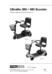
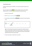
CE
The DHM Range
Users Instructions
WARNING: THIS APPLIANCE MUST BE EARTHED
£1.00 When supplied separately.
DHM Range Issue 1 July 1999
1. Lighting the Module
NOTE: On initial lighting of the module, it may take
some time to purge the internal pipework of air.
If it is not possible to light the module after
several attempts contact the local service
company.
1. To Start the Module
1.1 Follow the start up instructions for the duct
heater or air handling unit.
1.2 When all external and internal controls are
calling for heat the burner start-up sequence
will commence. The exhaust fan will run and
after a pre-purge period of approximately 30
seconds an ignition spark will be generated at
each burner.
The main gas valves will open and the burners
will be established
NOTE: If any burner fails to establish it will go to
lockout and the lockout indicator / reset button
on that burner control box will be illuminated.
To restart the burner push the lockout reset
button.
If a burner will not light after four or five
attempts then shut down the unit and call in
a service engineer.
NOTE: If there is loss of flame signal at any burner
during normal running the control box will
immediately initiate spark ignition. If the burner
fails to relight it will go to lockout.
2. To Shut Down the Module
2.1 For Short Periods:
Follow the instructions provided with the duct
heater or air handling unit so that external
and/or internal controls are not calling for
heat.
2.2 For Long Periods:
Complete 2.1 above, wait approximately 4-5
minutes for the exhaust fan of the module to
stop running and then turn OFF the gas and
electric supplies to the module.
3. Description of Operation
Important: All heaters must be controlled by the
fitted external controls and not by use of the main
switch in the electrical supply to the heater.
The burner start up sequence will commence
each time that the external controls call for heat.
The exhaust fan will run and after a pre purge
period off approximately 30 seconds an ignition
spark will be generated at each burner. The main
gas valves will be opened and the burners
established. When the external controls are satisfied
the burners will be turned off and approximately
4 - 5 minutes later the exhaust fan will be
automatically stopped.
4. Limit Thermostat
The limit thermostat is mounted towards the top
of the module inner panel.
i) Limit Thermostat Reset
In the event of a fault that causes the temperature
of the air within the module to rise significantly
e.g. Blocked air inlets, the limit thermostat will
operate to shut down the burners. Remove the
cause of the fault, wait 10 minutes and then reset
the thermostat by pushing the red reset button
(Refer to Figure 1 ). If the limit thermostat continues
to operate call a service engineer.
5. Maintenance
Regular servicing is essential to maintain efficient,
reliable and safe operation of the module. Users
are strongly recommended to have the module
serviced at least annually and preferably at the
end of the heating season.
6. IMPORTANT
Free access must be maintained to and around the
module for servicing purposes and the air supply
to the heater must not be restricted in any way.
Combustible materials must not be stored adjacent
to the module or the unit it is fitted into.
If at any time a gas leak is suspected turn OFF the
gas supply - DO NOT USE A NAKED FLAME - and
contact the local gas undertaking immediately.
Fig 1. Limit Thermostat
PUSH MAN
PULL AUTO
PUSH TO
RESET
Honeywell
Red
reset
button
BSI Registered Firm
FM 414
Ind. & Comm. Air Heaters;
Air Moving Equipment;
Flues & Chimneys; Natural
Smoke & Heat Ventilators;
Powered Supply & Extract
Fans & Systems.
HEATING DIVISION
Winterhay Lane
Ilminster, Somerset TA19 9PQ
Tel: 01460 53535 Fax: 01460 52341
Every effort is made to ensure accuracy at time of going to press. However as part of our policy of continual product improvement, we reserve the right to alter specifications without prior notice.