1
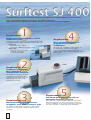
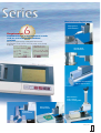
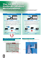
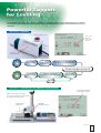
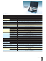
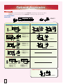
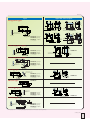
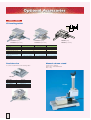
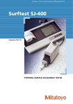
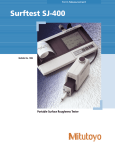
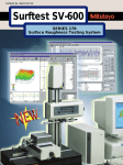
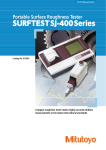
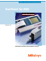
Surface-, Form- and Contour Measurement
Surftest SJ-400
Bulletin No. 1712
PORTABLE SURFACE ROUGHNESS TESTER
Revolutionary New Portable Surface Roughness Testers Make Their Debut!
Now, long-awaited specifications and functions are at hand: compactness,
skidless measurement, high-accuracy roughness detection, multi-function, and ease of operation.
1
4
Requirement
High-accuracy measurements with a
hand-held tester
A wide-range, high-resolution detector and an straight drive
unit provide superior high-accuracy measurement in its class.
<Detector>
Measuring range: 800µm
Resolution: 0.000125µm (at 8µm range)
<Drive unit>
Straightness/traverse length
SJ-402
SJ-401: 0.3µm/25mm
SJ-402: 0.5µm/50mm
Requirement
Measurement/evaluation of
stepped features and
straightness
Ultra-fine steps, straightness and waviness can
be measured by switching to the skidless
measurement function. The ruler function
enables simpler surface feature evaluation on the
LCD monitor.
SJ-401
2
SJ-401
Requirement
Roughness parameters
that conform to
international standards
The SJ-400 series performs 36 kinds
of roughness measurements that
conform to the latest ISO, DIN, and
ANSI standards as well as to JIS
standards (1994/1982).
3
Requirement
Measurement of cylinder surface
roughness even with a compact type
The skidless measurement and R-surface compensation
functions make it possible to evaluate cylinder surface
roughness.
2
5
Requirement
Advanced data processing with an
extended analyzing program
The SJ-400 series allows data processing that is identical to
that in the high-end class. These data analysis and report
creation capabilities can be achieved with this system using
the surface roughness analyzing program SURFPAK-SJ.
Measurement Applications
Deep groove
measurement
6
Requirement
Confirmation of a measurement results
and an assessed profile without
printout
Using the integrated large touch-panel LCD monitor,
measurement results and an assessed profile can be clearly
displayed.
Upside down
measurement
Calculation Result screen
Measured Profile screen
Cylinder measurement
with a support foot
Measurement
with a stand
and a leveling table
Fine contour
measurement
R-surface
measurement
Surftest SJ-400
3
The SJ-400 series employs a detector with exchangeable nosepiece that is interchangeable between skidless
measurement and skid measurement. It allows optional evaluation according to measurement conditions.
Skidless measurement
Skid measurement
Measuring
direction
Measuring
direction
Skid
• In skid measurement surface irregularities are
detected with reference to the skid that traces
waviness on a measuring surface, it cannot
measure waviness and stepped features exactly.
• This measurement facilitates the leveling of the
detector/drive unit.
• In skidless measurement surface irregularities are
detected with reference to the guide on the drive
unit, it can measure waviness and finely stepped
features in addition to surface roughness.
• The SJ-400 series supports a variety of surface feature
measurements by replacing the stylus.
Measuring
direction
Measuring
direction
Measuring
data
Measuring
data
Simplified surface feature evaluation
A variety of accessories
• A stylus and a nosepiece can be selected according to the
measurement condition. (See page 9 – 11.)
with the ruler function
• This function determines the coordinate difference between
two arbitrary points, such as a step height and a pitch
interval.
Nosepiece
Ruler
function
key
Ruler
Stylus
Ruler Analysis screen
Coordinate difference
4
Ruler key
Detector
The height-tilt adjustment unit comes as standard for powerful support of the leveling operation at skidless
measurement. This unique and convenient function has achieved high-accuracy measurement with ease of
operation.
The D.A.T. Function
Height adjusting knob
Turn the tilt
adjusting
knob by this
amount.
Tilt
adjusting
knob
Height-tilt
adjustment unit
With
D.A.T
DAT screen showing the amount to be adjusted
Preliminary
measurement
DAT screen
(adjustment
amount)
Adjustment of the tilt adjustment
knob by the specified amount
Final measurement
Without
D.A.T
Preliminary
measurement
Intuitive adjustment
using the tilt adjustment knob
Repeat
Confirmation
measurement
OK
NG
The D.A.T. Function for the optional leveling table
Move the micrometer
head by this amount.
When using with the stand,
the D.A.T. function can work with
the optional leveling table.
Leveling table
(for D.A.T.)
Digimatic
micrometer head
DAT screen showing the amount
to be adjusted
Surftest SJ-400
5
Support for R-surface roughness
measurement (skidless measurement)
Usually a workpiece with a spherical or cylindrical surface
cannot be evaluated. By eliminating the round surface element
with a filter, this function processes this R-surface data as if it
was taken from a flat surface.
Statistical processing function
This function performs statistical processing of multiple
measurements for one roughness parameter. It is possible to
display and print histograms in addition to statistical results
(mean, standard deviation, maximum value/minimum value,
and acceptance ratio).
Measurement
of a cylindrical
surface
Statistical
Measured profile
R-Surface
compensation
Switchable
Histograms
Assessed profile
Built-in thermal printer
A high-quality, high-speed thermal printer prints out measured results. It can also print a BAC curve or an ADC curve as well as
calculated result and assessed profile. These results and profiles can be printed out in landscape format, just as they appear on the
LCD. They are presented in an easy-to-understand form.
6
GO/NG judgment function
Auto-Calibration function
According to the upper/lower tolerance limits set the GO/NG
judgment sign is displayed and the calculation result is
highlighted (max. for 3 roughness parameters).
The SJ-400 series is equipped with the Ra calibration and step
calibration methods for detector calibration (gain adjustment).
In both calibration methods only the reference value described
in the precision specimen needs to be entered. No other
operation such as volume control is required.
GO sign
NG sign
Calculation Result screen with GO / NG judgment
result
Calibration screen
Real sampling function
This function samples a displacement of the stylus for the
specified time without traversing the detector.
It has a wide range of uses such as a simplified vibration meter
or a displacement gage incorporated in another system.
Recalculation function
It is possible to recalculate already measured data for other
evaluation by changing the current standard, assessed profile
and roughness parameters.
Saving/calling the measured data
and conditions
It is possible to save the measurement conditions and measured
data in the control unit or memory card (optional) and to recall
the data from both.
Batch printout of the measured data after performing on-site
measurement and saving the data will raise measurement
efficiency.
Saving capacity
Arbitrary length measurement
Measurement conditions
function
Measured data
This function allows a sampling length to be arbitrarily set in
0.1mm increments (SJ-401: 0.1mm to 25mm, SJ-402: 0.1mm to
50mm). It also allows the SJ-400 series to make both narrow
and wide range measurements.
Key masking function
Control unit: 5 conditions
Memory card: 20 conditions
Memory card: 50 or more pieces of data
Customize function
This function selects only the necessary parameters for
calculation/display from a variety of roughness parameters. It is
also possible to add parameters later for recalculation.
This function invalidates the key operation on the touch panel.
Since only the sheet key operation is valid, there is no chance
for error in data, including calibration conditions and
measurement conditions.
Invalidated
Customized screen
Surftest SJ-400
7
SJ-400
RS-232C
connecting
cable
(12AAA882)
Surface roughness analyzing program SURFPAK-SJ
In conjunction with SURFPAK-SJ, the SJ-400 series has the same
excellent operability and advanced analysis performance that is
achieved by a high-end desk top tester. The SURFPAK-SJ
increases the number of roughness parameters and analysis
graphs, and also allows the elimination of unnecessary data
and the evaluation of surface features including step and pitch.
In addition to surface roughness capabilities, the SJ-400 series
can make a total evaluation of a complete set of surface
features. This small system can be used as a high-end desktop
evaluation system.
(12AAA841)
Memory
card
SURFPAK®-SJ
COMPACTFLASHTM
Card Reader
Calculation
result display
Measurement
condition display
Evaluation Curve display
Printout
Analysis screen
Evaluation condition display
Analysis graph display
SURFPAK-SJ Specifications
Industrial standards met
Assessed profiles
Evaluation
Parameters
P, R, WC, WCA, WE,
WEA, DIN4776, E
R - motif
W - motif
Analysis graphs
Digital filter
Cutoff length*
Sampling length (L)*
Data compensation
Data deletion function
Recording magnifications
Special functions for report generation
OS requirement
ISO 4287:1997, ANSI / ASME B46.1-1995, JIS B0601 1994, etc.
P (primary profile), R (roughness profile), WC, WCA, WE WEA DIN4776 profile,
E (envelope residual profile), R - motif (roughness motif (waviness motif)
Ra, Rq, Rz, Rz(JIS), Ry, Ry (DIN), Rc, Rpi, Rp, Rpmax Rvi, Rv, Rvmax, Rti, Rt, R3zi, R3z, R3y, S, Pc (Ppi), Sm, HSC, mr, δc,
plateau ratio, mrd, Rk, Rpk, Rvk, Mr1, Mr2, ∆a, ∆q, λa, λq, Sk, Ku, Lo, Lr, A1, A2
Rx, R AR, SR, SAR, NR, NCRX, CPM
Wte, Wx, W, AW, SW, SAW, NW
ADC, BAC1, BAC2, power spectrum chart, auto-correlation chart, Walsh power spectrum chart, Walsh auto-correlation
chart, slope distribution chart, local peak distribution chart, parameter distribution chart
2CR-75%, 2CR-50%, 2CR-75% (phase corrected), 2CR-50% (phase corrected), Gaussian -50% (phase corrected)
λc: 0.025mm, 0.08mm, 0.25mm, 0.8mm, 2.5mm, 8mm, 25mm or arbitrary value (.001”, .003”, .01”, .03”, .1”, .3”, 1” or
arbitrary value)
fl: 0.25mm, 0.8mm, 2.5mm, 8mm or arbitrary value (.01”, .03” or arbitrary value)
fh: 0.25mm, 0.8mm, 2.5mm, 8mm or arbitrary value (.01”, .03” or arbitrary value)
0.025mm, 0.08mm, 0.25mm, 0.8mm, 2.5mm, 8mm, 25mm or arbitrary value (.001”, .003”,.01”, .1”, .3”, 1”)or arbitrary
value)
Tilt compensation, R-plane (curved surface) compensation, ellipse compensation, parabola compensation, hyperbola
compensation, Conic automatic compensation, polynomial compensation, polynomial automatic compensation
• Data deletion to avoid an over-range error
• Data deletion in a specific range to perform recalculation
• Automatic data deletion (according to conditions set previously)
Vertical:
100X - 500,000X
Horizontal: 1X - 10,000X
• Bit-map image paste-up function
• Multiple data layout function
Windows®95 / Windows®98 / Windows®NT4.0
* Arbitrary value can be specified in the following range: from 0.3mm (.012”) to the maximum traverse length.
8
Carrying case
is a standard
accessory
Specifications
Order No.*
SJ-401
SJ-402
Measuring method
Measuring range
Z-axis
X-axis
Drive method
Straightness
Measuring speed
Return speed
Height-Tilt adjustment unit Tilt adjustment range
Height adjustment amount
Assessed profile
Evaluation parameter
Analysis graph
Number of sampling length
Arbitrary length
Sampling length (L)
Printing width
Recording magnification
Detector
Function
Printer
Cut-off length
Digital filter
Calibration
Power supply
Battery
Power consumption
Dimension
Roughness standard
LCD size
Data output
External control
Mass
Standard accessories
Vertical magnification
Horizontal magnification
Detection method
Minimum resolution
Stylus tip
Measuring force
Radius of skid curvature
Skid force
Customize
Data compensation
Ruler function
D.A.T. function
Displacement detection mode
Statistical processing
Tolerance judgment
Measuring Condition storage
Charging time
Number of measurement
Control unit
Height-Tilt adjustment unit
Drive unit
Control unit
Height-Tilt adjustment unit
Drive unit
178-946-2 (mm)
178-940-2 (mm)
178-947-2 (inch/mm)
178-956-2 (mm)
178-957-2 (inch/mm)
178-945-2 (inch/mm)
178-958-2 (mm)
178-959-2 (inch/mm)
Skidless/Skid measurement
800µm, 80µm, 8µm (32000µin, 3200µin, 320µin) (Up to 2,400µm with an option stylus)
SJ-401: 25mm (1”) SJ-402: 50mm (2”)
SJ-401: 0.3µm/25mm (12µin/1”) SJ-402: 0.5µm/50mm (20µin/2”)
0.05, 0.1, 0.5, 1.0mm/s (.002”, .004”, .02”, .04”/s)
0.5, 1.0, 2.0 mm/s (.02”, .04”, .08”/s)
±1.5˚
10mm/.39”
Primary profile (P), Roughness profile (R), Filtered waviness profile (W), DIN4776, MOTIF (R, W)
Ra, Ry, Rz, Rq, Pc, R3z, mr, Rt, Rp, Rv, Sm, S, δc, Rk, Rpk, Rvk, Mr1, Mr2, A1, A2, Lo, Ppi, R,
AR, Rx, ∆a, ∆q, Ku, HSC, mrd, Sk, W, AW, Wte, Wx, Vo
Bearing Area Curve (BAC), Amplitude Distribution Curve (ADC)
X1, X3, X5, XL* (*=arbitrary length)
SJ-401: 0.1 to 25mm (0.1mm increments) [.01” to 2” (.01” increments)]
SJ-402: 0.1 to 50mm (0.1mm increments) [.04” to 2” (.01” increments)]
0.08, 0.25, 0.8, 2.5, 8mm (.003”, .01”, .03”, .1”, .3”)
48mm (1.89”)/paper width: 58mm (2.28”)
10 to 100K magnification, Auto
1 to 1K magnification, Auto
Differential inductance method
0.000125µm (8µm range)/.005µin (320µin range)
Corn 90°, Radius 5µm, Diamond
Corn 60°, Radius 2µm, Diamond
4mN
0.75mN
40mm/1.57”
Less than 400mN
Display/Roughness parameter selectable
R-surface, Tilt compensation
Displays the coordinate difference of any two points
Helps to adjust the leveling during the skidless measurement
Input the stylus displacement while the drive unit is stopped
Maximum value, Minimum value, Mean value, Standard deviation (s), Pass ratio, Histogram
Upper and lower limit values for three parameters can be specified
Five sets of measuring conditions (control unit)
Thermal printer
0.08, 0.25, 0.8, 2.5, 8mm (.003”, .01”, .03”, .1”, .3”)
2CR, PC75 (phase corrected), Gauss
Ra, Step (Automatic calibration entering the value of roughness specimen)
Via AC adapter, built-in rechargeable battery (Ni-H)
15 hours
600 maximum without printing
43W (max.)
307x165x94mm (12.09”x6.50”x3.7”)
131x63x99mm (5.16”x2.48”x3.90”)
SJ-401: 128x36x47mm (5.04”x1.42”x1.85”) SJ-402: 155x36x47mm (6.08”x1.41”x1.84”)
JIS (JIS B0601-1994-1982), DIN, ISO, ANSI
Touch panel
RS-232C input/output, SPC output
Connection to the data processing system (option)
1.2kg (2.64lbs.)
0.4kg (1.88lbs.)
SJ-401: 0.6kg (1.32lbs.) SJ-402: 0.64kg (1.41lbs.)
AC adapter, Carrying case, Printing paper, Touch pen, Protect sheet, Skidless nosepiece,
User’s manual, one-sheet manual, tools
* To denote your AC line voltage add the following suffixs (e.g. 178-946-2A). A for 120V, C for 110V, D for 220V, E for 240V, No suffix is required for 100V.
Surftest SJ-400
9
Detector
178-396-2: 0.75mN measuring force, with 12AAC731 standard type stylus (2µm tip radius)
178-397: 4mN measuring force, with 12AAB403 standard type stylus (5µm tip radius)
14
10
3.1
ø1
4
ø8
6.8 3.6
10.4
4
ø1
60
ø14
27.2
24
Skidless nosepiece
(12AAB355)
1.3
3.6
Set configuration/
Dimensions
ø7
Stylus
2.8
Skid nosepiece (12AAB344)
Detector
Unit: mm
ø1
Stylus tip
position
1.6
1.6
3.4
(
Extra small hole type
44.2
37.7
0.4
ø0.3
ø0.6
1.2
2.5
ø2.4
8.9
(
90°
Detail - A
(S=5/1)
A
): Tip radius
ø7.2
3.6
ø1
4
5.6
1.4
3.6
Stylus tip position
21.5
23.5
12AAC733 (2µm)*1
12AAB405 (5µm)
12AAB417 (10µm)
12AAB345
ø3
3.5
ø7.2
A
Distinguish
color
): Tip radius
90°
Detail - A
(S=5/1)
1.2
ø1.2
Distinguish
color
ø0.6
15.6
150°
6.8
3.6
0.6
12AAC732 (2µm)*1
12AAB404 (5µm)
12AAB416 (10µm)
4
6.7
3.5
R2
12AAB346
ø1
4
3.8
0.4
0.6
15
2.4
ø2.4
44.4
37.7
Stylus tip
position
12AAB344
ø1
5.6
3.6
21.5
23.5
3.8
0.6
90°
3.5
2.8
3.6
Detail - A
Ø7
.2
5.6
3.6
21.5
23.5
ø1.2
Small hole type
3.5
R40
): Tip radius
R40
(
4
6.7
0.9
5.2
7.6
ø2.4
Distinguish
color
12AAC731 (2µm)*1
12AAB403 (5µm)
12AAB415 (10µm)
R40
44.7
37.7
A
ø7.2
1.6
Standard type
Applicable skid nosepiece
R40
7.5
3.6
Stylus
21.5
22.3
2
ø1.9
1.2
Stylus tip position
12AAB347
Extra small hole type
44.2
37.7
0.4
12AAC734 (2µm)*1
12AAB406 (5µm)
12AAB418 (10µm)
0.8
2.5
ø2.4
8.9
ø0.6
0.8
ø0.3
Distinguish
color
A
(
90°
Detail - A
(S=5/1)
): Tip radius
Deep hole type
Detail - A
): Tip radius
Distinguish
color
Detail - A
0.9
5.2
7.6
5.2
7.6
Ø1.2
90°
2 x stylus
12AAC740 (2µm)
12AAB413 (5µm)
12AAB425 (10µm)
(
144.7
137.7
A
0.9
ø2.4
distinguish
color
ø2.4
94.7
87.7
A
ø1.2
90°
3 x stylus
12AAC741 (2µm)*1
12AAB414 (5µm)
12AAB426 (10µm)
(
): Tip radius
*1 Tip angle is 60°
Skidless nosepiece
3.6
1.3
ø1
4
ø7
3.5
4
Stylus tip position
10
21.5
10
12AAB355
Unit: mm
ø1
): Tip radius
Ø7.2
4
.2
R2
1.4
2.8
3.5
Stylus tip position
9
12AAB351
1.4
1
3
3
10
5
21.5
ø1.5
2.5
3.8
19.5
21.5
1.8
Stylus tip position
ø1
4
17.9
13.4
3.6
13.4
5 (8.4)
3.6
ø7.2
(
3.5
10
12AAC735 (2µm)*1
12AAB409 (5µm)
12AAB421 (10µm)
ø7
12AAB350
ø1
10
13
14.2
ø2.4
90°
5.6
3.6
21.5
23.5
Stylus tip position
4.4 1.4
9
1.4
R2
12AAB349
ø1.2
Detail - A
3.8
1.8
R40
Distinguish Color
10
10
19.5
21.5
Stylus tip position
3.5
0.6
0.9
A
12.8
R40
3.5
44.7
37.7
4
R40
3.6
13.4
ø1
4
3.6
4.5
ø7.2
Deep groove
Applicable skid nosepiece
4.5
Stylus
type*2
R2
5
9
11.6
12AAB352
Extra deep groove type*2
ø1.2
(
90°
27
22.8
ø1
4
12AAB348
3.5
Stylus tip position
19.5
21.5
): Tip radius
3.8
1.8
0.6
12AAC736 (2µm)*1
12AAB408 (5µm)
12AAB420 (10µm)
A
Distinguish
color
Detail - A
Ø7.2
20
23
24.2
37.7
44.7
R40
ø2.4
0.9
1.4
4.4 1.4
9
R2
Ø2.4
Extra deep groove type*2
ø2.4
A
Distinguish
color
Detail - A
12AAC737 (2µm)*1
12AAB407 (5µm)
12AAB419 (10µm)
5.2
33.8
35
37.7
45.2
(
ø1.2
): Tip radius
Detail - A
°
60
(
WE-curve type
44.7
37.7
19.7
): Tip radius
ø2.4
7.6
ø2.4
ø1.2
Detail - A
12AAC738 (2µm)*1
12AAB411 (5µm)
12AAB423 (10µm)
45
37.7
0.9
A
ø2.4
(
): Tip radius
ø1
4
21.5
23.5
5.6
Flat
3.6
2.8
Stylus tip position
3.5
12AAB354
10
7.6
ø2.4
4.5
5.2
7.6
Distinguish
color
90°
ø0.6
90°
12AAC739 (2µm)*1
12AAB412 (5µm)
12AAB424 (10µm)
(
*1 Tip angle is 60°
12AAB353
ø1.2
A
Distinguish
color
Detail - A
1.4
Ball ø1.588
0.9
Eccentric type*2
R2
1.4 4.4
12AAB338
0.9
Knife edge type
44.7
37.7
2.3
0.5
2.3
R40
6.7
3.6
.2
ø1
21.5
ø7.2
A
3.5
Stylus tip
position
4
6.1
3.6
6.4
12AAB339 (2µm)*1
12AAB410 (5µm)
12AAB422 (10µm)
7.6
ø2.4
60
°
Distinguish color
ø1
0.6
43.8
37.7
ø7.2
Gear face type
R40
90°
): Tip radius
*2 At using this stylus, measuring force of the detector does not guarantee.
Surftest SJ-400
11
XY leveling tables
3
7
4
Stand, Tables
13
178-042-1 (mm)
178-052-1 (inch/mm)
Order No.
Table size
Maximum loading weight
Inclination angle
Horizontal rotating angle
X, Y axis displacement
Min. reading
of the micrometer head
Dimension
Mass
178-043-1 (mm)
178-053-1 (inch/mm)
178-049 (mm)
178-059 (inch/mm)
178-042-1,178-052-1
178-043-1,178-053-1
178-049,178-059
130 x 100mm/5.12” x 3.94”
15Kg
±1.5˚
—
±3˚
—
±12.5mm/.49”
±12.5mm/.49”
±12.5mm/.49”
0.001mm/.00005”*
0.001mm/.001”*
0.001mm/.00005”*
262 x 233 x 83mm
6.3kg
220 x 189 x 83mm
6kg
262 x 233 x 55mm
5kg
* Digital display
Precision vise
Manual column stand
• Can be used with the XY leveling table.
Column travel: 200mm
Dimensions: 370x200x740mm
Mass: 13kg
178-019
Order No.
Mounting method
Clamp opening
Clamp width
Clamp depth
Height
12
178-019
Two-sliding- jaw
36mm/1.42”
44mm/1.73”
16mm/.63”
38mm/1.50”
178-009
Cylinder attachment
Measuring data output
Used to attach on a cylinder
Input tool
Diameter: ø15mm up to 60mm
Data input device for spread sheet software.
264-005
SPC connecting cables
Connects a control unit with DP-1VR.
1m: 936937
2m: 965014
DP-1VR
Performs various statistical processing
12AAB358
Leveling table
264-503 (100V)
264-503A (120V)
264-503D (220V)
264-503E (240/220V)
• Can be used with the XY leveling table.
Table swivels: ±1.5°
Table size: 130x100mm
Max. Loading weight: 15kg
Others
Memory card
Reference step specimen
Saves/Retrieves the measuring conditions
(up to 20), measured data, and statistical
data.
Memory: 8MB
Used to calibrate detector sensitivity.
Step nominal value: 2µm/10µm
12AAA841
178-048 (mm)
178-058 (inch/mm)
178-611 (mm)
178-612 (inch/mm)
LCD protective sheet
Printer paper
For touch panel protection
(10 sheets set)
Five rolls (25m)
99
(3.
Standard paper: 270732
Durable paper: 12AAA879
90
2 (.08")
")
Ø50 (1.97")
")
79
12AAA896
11
(3.
57
.5
(2.
26
")
Surftest SJ-400
13
Vision Measuring Systems
Surface-, Form- and Contour
Measurement
Digital Scale and DRO Systems
Optical Measuring
Sensor Systems
Hardness Measuring
Small Tool Instruments and
Data Management
Michigan
Phone: (734) 459-2810
Illinois
Phone: (630) 978-5385
California
Phone: (626) 961-9661
Note: All information regarding our products, and in particular the illustrations, drawings, dimensional and performance data contained
in this pamphlet, as well as other technical data are to be regarded as approximate average values. We therefore reserve the right to make
changes to the corresponding designs, dimensions and weights. The stated standards, similar technical regulations, descriptions and
illustrations of the products were valid at the time of printing. In addition, the latest applicable version of our General Trading Conditions
will apply. Only quotations submitted by ourselves may be regarded as definitive.
Massachusetts
Phone: (978) 692-8765
Indiana
Phone: (317) 577-6070
North Carolina
Phone: (704) 875-8332
Job No.11B-8
26.800308 (1) CNE, Printed in Japan
Coordinate Measuring Machines