1
Form Measurement
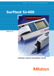
Portable Surface Roughness Tester
SURFTESTSJ-400Series
Catalog No. E15005
Compact roughness tester makes highly accurate skidless
measurements to the latest international standards
Revolutionary Portable Surface Roughness Tester
Long-awaited performance and functionality are here:
compact design, skidless and high-accuracy roughness
measurements, multi-functionality and ease of operation.
SJ-401
High-accuracy measurements with a hand-held tester
A wide range, high-resolution detector and an ultra-straight drive unit provide class-leading accuracy.
Detector
Measuring range: 800 µm (on 800 μm range)
Resolution: 0.0001 μm (on 8 μm range)
Drive unit
Straightness / traverse length
SJ-401: 0.3 µm / 25 mm
SJ-402: 0.5 µm / 50 mm
Measurement/evaluation of stepped features and straightness
Ultra-fine steps, straightness and waviness are easily measured by switching to skidless measurement mode.
The ruler function enables simpler surface feature evaluation on the LCD monitor.
Cylinder surface roughness measurements with a hand-held tester
The skidless measurement and R-surface compensation functions make it possible to evaluate cylinder surface
roughness.
2
SJ-402
SJ-401
Roughness parameters that conform to international standards
The SJ-400 series can evaluate 38 kinds of roughness parameters conforming to the latest ISO, VDA, and ANSI
standards, as well as to JIS standards (2001/1994/1982).
Positioning of measurement start point
The drive mechanism on the SJ-400 series can be controlled simply by manipulating icons on the LCD monitor.
You can start measurement from any position you choose.
Confirmation of measurement results and assessed profiles without a printout
The large, integrated, touch-panel LCD monitor clearly displays evaluation results and measured profiles.
Calculation Result screen
Measured Profile screen
Advanced data processing with extended analysis (Option)
The SJ-400 series allows data processing identical to that in the high-end class. These data analysis and report
creation capabilities are achieved using the surface roughness / contour analysis software FORMTRACEPAK.
3
Your choice of skidless or skidded measurement
Patent registered in Japan. Patent pending in Germany.
The Surftest SJ-400 series can switch between skidless or skidded measurement.
Skidless measurement can measure finely contoured features and has an R-surface compensation function for measuring around the
circumference of cylinders.
Skidless measurement
Skidded measurement
Skidless measurement is where surface features are measured
relative to the drive unit reference surface.This measures waviness
and finely stepped features accrately, in addition to surface
roughnness, but range is limited to the stylus travel available.
The SJ-400 series supports a variety of surface feature
measurements
simply by replacing the stylus.
Traverse direction
Detector
In skidded measurements, surface features are measured with
reference to a skid following close behind the stylus. This cannot
measure waviness and stepped features exactly but measuring
range is greater because the skid tracks the workpiece surface
contour.
Traverse direction
Detector
Traverse direction
Fulcrum point of Stylus
Stylus
Measuring example of stepped
features: Skidless
Fulcrum point of Skid
Fulcrum point of Stylus
Stylus
Skid
Measured profile
Traverse direction
Traverse direction
Measuring example of stepped
features: Skidded
Measured profile
測 定
Interchangeable attachments for high versatility
Ruler function simplifies surface feature evaluation
Ruler function key
This function determines
the coordinate difference
between two arbitrary points
測 定so feature characteristics,
such as step測 定
height and
width, etc., can be measured.
Attachments such as
Nosepiece
the stylus and nosepiece
can be changed測 定
to
suit different types of
測 定
measurement.
(See pages
8 and 9.)
Detector
測 定
測定データ
Ruler
Ruler Analysis
Ruler key
screen
Coordinate difference
Stylus
Powerful Support for Leveling
The height/tilt adjustment unit comes as standard for leveling the drive unit prior to making skidless measurements and,
supported by guidance from the unique D.A.T. function, makes it easy to achieve highly accurate alignment.
The D.A.T. Function
Patent registered in Japan. Patent pending in German.
Height/tilt adjustment unit
Turn tilt adjustment knob by 1.37
turns counter-clockwise to level
Height adjustment
With
DAT
Preliminary
measurement
DAT screen
(adjustmentamount)
Without
DAT
Preliminary
measurement
Intuitive adjustment
using the tilt adjustment knob
Final measurement
Repeat
Tilt adjustment
OK
NG
DAT screen guides the user when leveling
D.A.T. Function for the optional leveling table
Patent registered in Japan. Patent pending in German.
Adjustments can be performed via the
leveling table even when using the
manual column stand. The adjustment
operation is intuitive with the movement
distance displayed on the screen.
Digimatic micrometer head
Adjust the micrometer
head by -0.928 mm to level
Leveling table (D.A.T.)
(optional)
DAT screen guides the user when leveling
4
More Measuring Functions Than Expected From a Compact Tester
Measuring curved-surface roughness (skidless measurement)
Usually, a spherical or cylindrical surface
(R-surface) cannot be evaluated, but,
by removing the radius with a filter,
R-surface data is processed as if taken
from a flat surface.
R-Surface
compensation
Built-in thermal printer
A high quality, high-speed thermal printer prints
out measured results. It can also print a BAC
curve or an ADC curve as well as calculated results
and assessed profiles. These results and profiles
are printed out in landscape format, just as they
appear on the LCD, in easy-to-understand form.
Statistics
GO/NG indication
Statistical processing can
be performed on multiple
measurements for one
roughness parameter.
Histograms can be displayed
and printed in addition to
statistical results (mean, standard
deviation, maximum/minimum Switchable
value and acceptance ratio)
Upper and lower tolerance limits
can be set for up to 3 roughness
parameters. A GO/NG indication
is displayed after a measurement.
The calculation result is
highlighted if NG.
Statistical
Calculation Result screen with
GO/NG judgment result
Histograms
Auto-Calibration
Recalculating
The SJ-400 series is equipped with Ra
calibration and step calibration methods
for detector calibration (gain adjustment).
In both calibration methods only the
calibrated value of the precision specimen
needs to be entered. No other operations
are required to calibrate the tester.
Previously measured data can be recalculated for use in other
evaluations by changing the current standard, assessed profile
and roughness parameters.
Arbitrary length measurement
This function allows a sampling length to be arbitrarily set in
0.1mm increments (SJ-401: 0.1mm to 25.4mm, SJ-402: 0.1mm
to 50.8mm). It also allows the SJ-400 series to make both
narrow and wide range measurements.
Calibration screen
Storing/recalling measured data and conditions
The measurement conditions and data can be stored in the
control unit or memory card (optional) and recalled as required.
Batch printout of data after on-site measurement improves
measuring efficiency.
Customizing
The SJ-400 series can be
set up to calculate and
display only a subset of
the roughness parameters
available. Parameters can be
added later for recalculation,
if required.
Storage capacity
Measurement
conditions
Measurement data
GO sign
NG sign
Control unit: 5 conditions
Memory card: 20 conditions
Memory card: 999 or more items of data
Key masking
Locks out input from the touch
panel keys. This eliminates
the possibility of the operator
accidentally changing the
calibration or measurement
conditions.
Customized screen
Carrying Case
The unit is easily transported in
a dedicated carrying case which
includes holders for the accessories
as well as the tester itself. (Standard
accessory.)
Invalidated
Real sampling
This function samples stylus displacement for a specified
time without engaging detector traverse. This function has a
wide range of uses, such as a simplified vibration meter or a
displacement gage incorporated in another system.
5
Specifications
Model No.
Type of detector
Order No.
mm / inch
mm*1
inch / mm
SJ-401
4 mN
178-946-4
178-946-4K
178-947-4
0.75 mN
178-958-4
178-958-4K
178-959-4
SJ-402
4 mN
178-940-4
178-940-4K
178-945-4
25.4 mm (1”)
50.8 mm (2”)
800 μm / 80 μm / 8 μm (32000 μinch / 3200 μinch / 320 μinch) Up to 2,400 μm with an optional stylus
Differential inductance
0.01 μm (800 μm range) / 0.001 μm (80 μm range) / 0.0001 μm (8 μm range)
Resolution
0.4 μinch (32000 μinch) / 0.04 μinch (3200 μinch) / 0.004 μinch (320 μinch)
Detector*1
Stylus tip
60° / R2 μm (80 μin)
90° / R5 μm (200 μin)
60° / R2 μm (80 μin)
90° / R5 μm (200 μin)
Measuring force
0.75 mN
4 mN
0.75 mN
4 mN
Radius of skid curvature
R40 mm (R1.57")
Measuring method
Skidded measurement / skidless measurement
Measuring speed
0.05, 0.1, 0.5, 1.0 mm/s (0.002, 0.004, 0.02, 0.04 inch/s)
Drive unit: X-axis
Drive speed
0.5, 1, 2.0 mm/s (0.02, 0.04, 0.08 inch/s)
Straightness
0.3 μm / 25 mm (12 μinch / 1 inch)
0.5 μm / 50 mm (2 μinch / 1inch)
10 mm (0.39")
Height-tilt adjustment Height adjustment
unit
Tilt adjustment
±1.5°
Conformable standards
JIS1982 / JIS1994 / JIS2001 / ISO1997 / ANSI / VDA
Ra, Ry, Rz, Rq, Pc, R3z, mr, Rt, Rp, Rv, Sm, S, δc, Rk, Rpk, Rvk, Mr1, Mr2,
Parameters
A1, A2, Lo, Ppi, R, AR, Rx, Δa, Δq, Ku, HSC, mrd, Sk, Vo, W, AW, Wt, Wte, Rz1max (ISO), Rmax (VDA, ANSI)
Primary Profile, Roughness profile, Filtered waviness curve
Assessed profiles
Roughness motif, Waviness motif, DIN4776 curve
Graphs
Bearing Area Curve (BAC), Amplitude distribution Curve (ADC)
Data compensation
Tilt compensation, R-surface compensation, Compensation off
Filters
2CR, PC75, Gaussian filter,
λc
Cutoff length
0.08, 0.25, 0.8, 2.5, 8 mm (0.003", 0.01", 0.03", 0.1", 0.3")
Sampling length
0.08, 0.25, 0.8, 2.5, 8 mm (0.003", 0.01", 0.03", 0.1", 0.3")
Number of sampling lengths (×n)
×1, ×3, ×5
Arbitrary length
0.5 to 25.4 mm
0.5 to 50.8 mm
Customize
Display/Roughness parameter selectable
Ruler function
Displays the coordinate difference of any two points
D.A.T. function
Helps to adjust leveling during skidless measurement
Real sampling function
Enables the stylus displacement to be input while the drive unit is stopped
Statistical processing
Maximum value, Minimum value, Mean value, Standard deviation(s), Pass ratio, Histogram
Tolerance judgment
Upper and lower limit values for three parameters can be specified
Display unit
Measurement conditions saving
5 cases max. (Display unit)
Waveform (profile, BAC1, BAC2,ADC), Calculation result, Statistics result, Frequency table
Printing function
Measurement condition, Memorandum, Hard copy of a screen
Diplay languages
Japanese, English, German, French, Italian, Spanish
Memory card
Storage/recall of measurement condition (20 cases max.) and measurement data (999 cases max.)
(128 MB, Optional Accessory)
External input / output
RS-232C input/output, SPC output
Two-way power supply: battery (rechargeable Ni-MH battery) and AC adapter
Power supply
*Charging time: about 15 hours (may vary due to ambient temperature)
*Endurance: about 600 measurements without printing (differs slightly due to use conditions/environment)
Diplay unit
307×165×94 mm (12"×6.5"×3.7")
Size
Height adjustment unit
131×63×99 mm (5.16"×2.48"×3.9")
Drive unit
128×36×47 mm (5.04"×1.42"×1.85")
155×36×47 mm (6.08"×1.42"×1.85")
Diplay unit
1.2 kg
Mass
Height adjustment unit
0.4 kg
Drive unit
0.6 kg
0.7 kg
*2
*3
Detector , Stylus , Roughness specimen
12AAA357: Carrying case
12BAA689: Touch pen
Standard accessories
12BAA690: Touch-panel protection sheet
270732: Printing paper
Flat-blade screwdriver, Hexagonal wrench, AC adapter, Power cord, User's manual
Quick reference manual, Warranty
*1: Specification for Korea.
*2: Either No.178-396 or No.178-397 is supplied as a standard accessory depending on the Order No. of the main unit for SJ-400 Series.
*3: The standard stylus (No.12AAC731 or No.12AAB403), which is compatible with the detector supplied, is a standard accessory.
Note 1) See pages 8 , 9 for details about stylus, detector, nosepiece.
2) To denote your AC line voltage add the following suffixes (e.g. 178-956-4A), A for 120 V, D for 220 V, E for 240 V, DC for 220 V (for China), 4 K for 220 V (for Korea)
Factory default unit
System of units
Factory default unit
Remarks
mm
mm
The unit is mm only
mm / inch
mm
The unit can be switched to inch
inch / mm
inch
The unit can be switched to mm
Measuring
range
X-axis
Z1-axis (detector unit)
Detecting scheme
0.75 mN
178-956-4
178-956-4K
178-957-4
6
Dimensions
SJ-401
Unit: mm
131
63
1
0
9
94
PRINT
CONDITION
READ
FEED
DATA
START
STOP
15°
307
207.5(234)
*The dimensions in parentheses indicate those for SJ-402
Example of mounting on manual column stand. (Code No. 178-039)*
*For details see page 10.
Unit: mm
556
25(50)
40
15
T-slot dimensions
60
175(201.5)
400
40
7
11
250
8.5
120
10
90
99
165
S J - 4 0 0
250
Measuring range
*The dimensions in parentheses indicate those for SJ-402
7
Option: Detectors / Styli
Detectors
2.5
ø2.4
ø1.2
1.6
ø1.2
3.4
1.6
ø2.4
2.4
ø2.4
ø1.2
ø0.3
ø2.4
Ball ø0.5
ø2.4
8.5
3.1
4
ø0.3
ø1
Detail-A
37.7
43.8
A
ø1.9
For small slotted hole*6
12AAE938 (2μm) *5
12AAE940 (5μm)
0.4
90°
0.6
ø0.6 Ball ø0.5
Detail-A
Tip radius
1 μm
深穴用
2 μm
Color coding
White
Black
A
7
45
Detail-A
43.8
37.7
94.4
87.7
7
A
5 μm
10 μm
250 μm
No color
Yellow
No notch or color
*8 : Used for calibration, a standard step gauge (No.178-611, option) is also required
ø2.4
0.6
1.6
ø2.4
144.7
137.7
A
ø2.4
スタイラス先端位置
ø1.2
8
細穴形状用
12AAJ662
(ø0.5mm)
For Ultra-small hole*8
ø1.2
ø0.3
2
1.2
21.5
22.3
ø2.4
ø1.2
ø0.3
A
ø2.4
ø7.2
ø0.6
ø2.4
3
1.8
0.6
2.4
ø7.2
3.6
7.5
R40
0.4
ø0.6
A部詳細
7.6
5.2
*7 :
3.4
ø2.4
1.6
ø2.4
2.5
*5 : Tip angle 60°
*6 : For downward-facing measurement only.
3.5
Detail-A
90°
87.7
Ball ø1.6
0.6
45
Color coding*7
ø1.2
93.8
94.4
0.8
Detail-A
12AAE884
(ø1.6mm)
*1
87.7(2µm)
12AAE938
41
12AAE940(5µm)
0.6
0.8
A
小穴用・深穴2倍
For small
hole*8
A
Color coding
3.8
ø2.4
0.9
12AAE885(ø 0.5mm)
A
*7
3×
超小穴用
0.9
12AAC741 (2μm) *5
12AAB414 (5μm)
12AAB426 (10μm)
( ): Tipradius
94.7
87.7
ø2.4
12AAC740 (2μm) *5
12AAB413 (5μm)
12AAB425 (10μm)
( ): Tipradius
Color coding
*7
7.6
5.2
For deep hole*6
2×
A
94.4
87.7
30
Detail-A 37.7
A部詳細
Ultra-small hole type
ø1.2
ø1.2
Parts No.12AAB347
3.5
ø1.9A部詳細2
A部詳細
21.5
Remarks
90°
1.2
22.3 90°
Hole diameter: More
than ø2.3 Hole depth: Less than 6.5
Stylus tip position
2倍
3倍
(2µm)*1
12AAC740
12AAC741(2µm)*144.2
0.4
Extra-small hole
12AAB413(5µm)
12AAB414(5µm) 37.7
12AAC734 (2μm) *5
12AAB425(10µm)
(8.9
10µm)
12AAB426
ø0.3
12AAB406 (5μm)
( )
:先端半径
( )
:先端半径
12AAB418 (10μm)
90°
6.7
( ): Tipradius
Detail-A
*1:先端角度 60°
Color coding*7
(S=5/1)
0.6
43.8
細長穴用
144.7
137.7
A
ø2.4
ø2.4
ø1.2
44.2
37.7
3.6
0.6
ø2.4
ø0.5超硬球
12AAE884(ø1.6mm)
ø0.6
7
7.6
5.2
6.7
0.6
7
R40
A
Color coding*7ø1.6超硬球
3.8
0.9
ø1
4
3.6
R40
Nosepiece
ø0.3
8.9
90°
A
Detail-A
0.9
(S=5/1) 識別色
94.7
87.7
12AAE892 (2μm) *5
12AAE908 (5μm)
( ): Tip radius
41
(2µm)*1
12AAC734
3.5
21.5
(5µm)
12AAB406
23.5
12AAB418(10µm)
( )
:先端半径
0.4
93.8
For small
hole / Double-length for deep hole*6
87.7
極細穴形状用
識別色
7.6
5.2
識別色
ø0.6
A
*5
5.6
3.6
1.4
Stylus tip position
1.2
0.8
2.5
0.8
8.9
15.6
Stylus tip position
ø2.4
37.7
R2
3.8
ø344.2
3.6
4
ø1
Small hole type
0.4
Parts No.12AAB346
Remarks
Hole diameter: More than ø4
Hole depth: Less than ø0.3
15
R40
Nosepiece
超小穴用
90°
Ultra-small hole
type
A部詳細
( )
:先端半径
90°
Detail-A
A
識別色
(S=5/1)
ø0.6
A
12AAB417(10µm)
( )
:先端半径
3.5
21.5
23.5 A
細穴形状用
44.4
*137.7
0.6(2µm)
12AAC733
15
12AAB405(5µm)
ø0.6
3.4
1.6
2.5
1.2
ø0.3
1.6
8.9
ø2.4
1.2
0.4
44.2
37.7
90°
A部詳細
(S=5/1)
12AAC733(S=5/1)
(2μm)
12AAB405 (5μm)
12AAB417
(10μm)
深穴用
( ): Tipradius
0.6
ø0.6
5.6
3.6
150°
6.8
2.4
識別色
5.6
21.5
3.6
23.5
Stylus tip position
ø0.6
2.8
極細穴用
Small hole
type 0.4
12AAC732 (2μm) *5
12AAB404 (5μm)
12AAB416 (10μm)
( ): Tip radius
ø2.4
6.7
A
ø1.2
ø
30
A部詳細
12AAE892(2µm)*1
87.7
12AAE908(5µm)
0.9
87.7
0.6
Cylinder type
Parts No.12AAB345
Remarks ø2-20
3.5
94.4
ø1.4
1.6 ø7.2
3.6
ø14
R40
7.2
2.4
3.4
1.6
1.6
ø0.6
94.7
0.6
( )
:先端半径
1.2
0.4
15
90°
No.12AAB344
A部詳細
(S=5/1)
12AAE898 (2μm) *5
12AAE914 (5μm)
( ): Tip radius
小穴用・深穴2倍
*1
ø1.2 (2µm)
12AAC732
(5µm)
12AAB404
90°
12AAB416(10µm)
44.4
37.7
Detail-A
Standard type
7.6
5.2
Color
coding*7
0.6
Nosepiece
*6
( )
:
先端半径
Double-length for deep
hole
( )
:先端半径
A
90°
12AAE898(2µm)*1
12AAE914(5µm)Unit: mm
94.7
87.7
0.9
0.6
ø1.2
3
ø2.4
識別色
7.6
5.2
A
12AAE882 (1 μm)*5
A部詳細
12AAE924
(1 μm)
12AAC731 (2 μm)*5
12AAB403 (5 μm)
12AAB415
(10 μm)
小穴用
12AAE883*8 (250 μm)
( ): Tip radius 0.6
Parts
深穴2倍用
12AAE882(1µm)*1
12AAE924(1µm) Styli
12AAC731(2µm)*1
12AAB403(5µm)
10µm)
12AAB415(
44.7
(250µm)*1
12AAE883
0.9
37.7
44.7
37.7
0.9
Standard type
ø14
Nosepiece
Detector
(12AAB344)
Skid
標準スタイラス
ø7.2
2.8
14
ø8
6.8 3.6
10.4
60
ø1
4
1.3
3.6
27.2
24
4
ø1
Detector
ø2.4
Skidless nosepiece
(12AAB355)
4
ø0.3
ø7
Skidded
Code No.
Measuring force
0.75 mN
178-396-2*1,*3
4 mN
178-397-2*1,*4
0.75 mN
178-396*2,*3
4 mN
178-397*2,*4
10
Standard accessories
検出器
3.1
*1: Skidless nosepiece
(12AAB355)
*2: Skidless nosepiece (12AAB355), Skidded nosepiece (12AAB344)
ø7 *3: Standard stylus (12AAC731)
ノーズピース
*4: Standardスタイラス
stylus (12AAB403)
ø8
ø1
4
1.3
3.6
14
ø1.2
60
3.1
1.8
11.5 10
ø14
Skidless
Unit: mm
細長穴用
極細穴形状用
Styli
3
21.5
Detail-A
43.8
42.6
5.2
コーナー用ノーズピース
5.2
0.5
ø3
44.3
37.7
穴測定コーナー用
・深穴2倍
*1: Tip angle 60°
*3 :
Tip radius
2 μm
5 μm
10 μm
転がり円
*2: For downward-facing measurement only.
Color coding
Black
No color
Yellow
Note: Customized special interchageable styli are available onうねり用
request.
*4 : Used for calibration, a standard step gauge (178-611, optional) is also required
Please contact any Mitutoyo office for more information.
9
ø2.4
ø2.4
6.7
7
5.8
5
ø1.6
ø7.2
Ball ø1.588
12AAE899 (2μm)*1
12AAE915 (5μm)
( ): Tip radius
ø1
ø1.2
転がり円うねり・深穴2倍
Bottom surface type
44.7
37.7
93.8歯面用
87.7 深穴2倍
35
12AAE897 (2μm)*1
12AAE913 (5μm)*1
( ): Tip radius
Stylus tip position
3.5
21.5
19.7
ø2.4
7.6
5.2
0.9
Corner bold type•
Double-length for deep hole*2
.8
Rolling circle waviness type*4
ø1.2
ø0
1.4 4.4 1.4 R2 2.3
0.5
2.3
歯面用
12AAE886 (250μm)
94.7
87.7
0.9
7.4
6.2
3.6
0.6 6.1
12AAB353
ø1.2
Rolling circle waviness type•
Double-length
for deep hole*2*4
45°
Corner surjace
R40
ø14
4.5
Nosepiece
A
ø1.
2
深溝用(30mm)
深穴2倍
5
7.6
60°
6.4
深溝用(30mm)
60°
Detail-A
ø3
深溝用(20mm)
43.8
37.7
Color coding*3
36.5
35
12AAE896
(2μm)*1
90°
12AAE912 (5μm)*1
( ): Tip radius
ø1.2
12AAB339 (2μm)*1
12AAB410 (5μm)*1
12AAB422 (10μm)*1
( ): Tip radius
93.8
87.7
*2
Double-length
φ1.2 for deep hole
A部詳細
90°
Gear face type
深溝用(40mm)
ø1.2
36.5
35
A
Color coding*3
Detail-A
心違い
93.8
87.7
60°
33
31.8
5.2
ø2.4
37.7
45.2 識別色
ø1.2
ø2.4
φ2.4
37.7
44.7
A type•
Gear face
24.2
23
0.6
Extra deep groove*2 (30mm)
ø2.4
90°
Detail-A
7.6
6.4
5.2
ø7.2
12AAE894 (2μm)*1
12AAE910 (5μm)
( ): Tip radius
0.9
3.5
19.5
21.5
3.8
1.4 4.4 1.4
9
R2 1.8
Stylus tip position
*1
ø7.2
深溝用2倍(20mm)
Deep groove type (30mm) •
Double-length for deep hole*2
20
22.8
27
Remarks
Groove depth: Less than 20
Groove width: More than 9.5
45.2
37.7
0.9
A
ø1.2
R40
Deep groove 20
12AAB348
ø2.4
7.6
6.7
ø2.4
45.2
37.7 識別色
12AAE895 (2μm)*1
12AAE911 (5μm)
( ): Tip radius
90°
Nosepiece
12AAB338 (ø1.588)
10
Deep groove type*2 (40mm)
A
ø1.2
ø14
12AAC737 (2μm)
12AAB407 (5μm)
12AAB419 (10μm)
( ): Tip radius
ø1.2
ø2.4
24.2
23
Color coding*3
7.6
Stylus tip position
44.7
37.7
Extra deep groove (20mm)
ø2.4
ø2.4
10
5
3.5
7.6
10
3
R2
*2
12AAC736 (2μm)*1
12AAB408 (5μm)
12AAB420 (10μm)
( ): Tip radius
95.2
87.7
ø2.4
5
9
11.6
12AAE893 (2μm)*1
12AAE909 (5μm)
( ): Tip radius
ø2.4
1.4
Remarks
Depth: Less than 10, Width: More than 3
90°
ø2.4
4.5
3.6
13.4
17.9
3.5
1
10
R40
R40
13.4
3.6
ø14
21.5
R2 5.6
3.6
23.5
Stylus tip position
ø1.2
Color coding*3
Deep groove type*2 (20mm)
ø7.2
4
ø1
45.2
37.7
1.4
A
ナイフエッジ用ノーズピース
Detail-A
Seesaw groove
12AAB352
12AAB350
1.4
2.8
10
Remarks 9
凸surface: More than R1.5
凹surface: More than R3
ナイフエッジ用
3.5
21.5
23.5
ø2.4
Narrow groove
2
ø7.2
3.6
10
Remarks
Depth: Less than 10, Width: More than 9.5
10
Parts No.
12AAC739 (2μm)*1
12AAB412 (5μm)
12AAB424 (10μm)
( ): Tip radius
3.8
19.5
21.5
1.8
Stylus tip position
ø1.5
2.5
19.5
21.5
5.6
2.8
3.6
Stylus tip position
Flat
Eccentric type*2
3.5
5 (8.4)
13.4
ø7.2
4.5
3.6
12.8
0.6
R40
R2
3.8
1.4 1.8
1.4 4.4
9 Stylus tip position
ø7.
Knife edge type
12AAB354
ø14
3.5
ø14
Nosepiece
R-surface
12AAB351 深溝用
(10mm)
Deep groove 10
12AAB349
ø1.2
90°
23
21.8
5.2
Nosepiece
44.7
37.7
0.9
Detail-A
90°
ø14
Color
coding*3
ø1.2
Detail-A
A
ø2.4
12AAC738 (2μm) *1
12AAB411 (5μm)
12AAB423 (10μm)
( ): Tip radius
ø2.4
14.2
13
Color coding*3
Knife-edge type
44.7
37.7
A
0.9
12AAC735 (2μm)*1
12AAB409 (5μm)
12AAB421 (10μm)
( ): Tip radius
3.6
R40
Deep groove type (10mm)
Unit: mm
穴底用
Optional accessories
Stand, Tables
XY leveling tables
178-042-1
Application
178-049
• Movement is in X- and Y-axis only.
Order No.
178-042-1 (with digital heads) 178-043-1 (with analog heads) 178-049 (with digital heads)
Table dimensions
130 × 100 mm
Maximum load
15 kg
Inclination adjustment angle
± 1.5°
—
Swiveling angle
± 3°
—
X/Y-axis travel range
±12.5 mm
±12.5 mm
±12.5 mm
Resolution
0.001 mm
0.01 mm
0.001 mm
Dimensions (WxDxH) 262 × 233 × 83 mm 220 × 189 × 83 mm 262 × 233 × 55 mm
Mass
6.3 kg
6 kg
5 kg
• T-slot dimensions
7
4
(178-042-1/178-043-1)
• Fits on the stand.
3
The tester includes X- and Y-axis
micrometer heads. This makes axis
alignment much easier because the tilt
adjustment center is the same as the
rotation center of the table.
Precision vise
13
Unit: mm
Manual column stand for SJ-400 Series
Leveling table (for D.A.T. function)
Can be adjusted to match
the height of the item to be
measured.
Can be used together with the XY
leveling tables.
Patent pending in Japan, U.S.A, German.
178-039
178-019
Sliding jaws
36 mm
44 mm
16 mm
38 mm
Order No.
Clamping method
Jaw opening
Jaw width
Jaw depth
Height
Cylinder attachment
A block that can be positioned on
top of cylindrical objects to perform
measurements.
12AAB358
Diameter: ø15~60 mm
Vertical adjustment range: 250mm
Dimensions: 400×250×556mm
Mass: 20kg
178-048
Inclination adjustment angle: ±1.5°
Table dimensions: 130×100mm
Maximum load: 15kg
*Drive unit is not included
Measuring data output
Input Tool: Calculation results input unit
Digimatic mini processor DP-1VR
Surftest SJ-400 series calculation results can be loaded directly
into commercial spreadsheet software via this unit simply by
connecting it to the USB connector on a computer or a PS/2
type keyboard connector. (See Catalog Nos. E4250-264, E4391 for
details.)
For USB keyboards
IT-012U 264-012-10*
USB-ITN-D 06ADV380D
For PS/2 keyboards
IT-005D 264-005*
Provides an extensive range of statistical analyses.
264-504
To denote your AC line voltage add the following suffixes (e.g.264504-5A).
5A for 120V, 5D for 230V, 5E for 230V (for UK), 5DC for 220V (for
China), 5K for 220V (for Korea), 5F for 230V (for Oceania)
*The following Digimatic output cable (option) is required for
connecting with SJ-400 series.
Digimatic output cable
•1m 936937
•2m 965014
*Digimatic output cable (option) is required separately.
Others
Memory card
Reference step specimen
Stores/recalls measuring conditions (20 max.),
measured data, and statistical data.
Memory: 128 MB
12AAA841
Used to calibrate detector sensitivity.
178-611
Step nominal values: 2µm/10µm
LCD protective sheet
For touch panel protection
(10 sheet set) 12AAA896
Printer paper (for SJ series)
Five rolls (25m)
Standard paper: 270732
Durable paper: 12AAA876
2
99
79
Unit: mm
ø50
57.
5
10
Unit: mm
Contour / Roughness analysis software
FORMTRACEPAK
More advanced analysis can be performed by loading SJ-400 series
measurement data to software program FORMTRACEPAK via a
memory card (option) for office processing.
SJ-400
FORMTRACEPAK
Simplified communication program
for SURFTEST SJ-400 series
The Surftest SJ-400 series has an RS-232C interface, enabling data to be transferred to a spreadsheet or other software.
We also provide a program that lets you create inspection record tables using a Microsoft Excel* macro.
This program can be downloaded for free from
the Mitutoyo website.
http://www.mitutoyo.co.jp
Required environment*
• OS :Windows 2000 SP4
Windows XP
Windows Vista
Windows 7
• Spreadsheet software:
Microsoft Excel 2000
Microsoft Excel 2002
Microsoft Excel 2003
Microsoft Excel 2007
*Windows OS and Microsoft Excel are products of
Microsoft Corporation.
Required accessories
• RS-232C cable for SJ-400 series
12AAA882
11
Mitutoyo Corporation
Note: All information regarding our products, and in particular the illustrations, drawings, dimensional and performance data contained in this pamphlet, as well as other
technical data are to be regarded as approximate average values. We therefore reserve the right to make changes to the corresponding designs, dimensions and weights.
The stated standards, similar technical regulations, descriptions and illustrations of the products were valid at the time of printing. Only quotations submitted by ourselves
may be regarded as definitive.
Our products are classified as regulated items under Japanese Foreign Exchange and Foreign Trade Law. Please consult us in advance if you wish to export our products to
any other country. If the purchased product is exported, even though it is not a regulated item (Catch-All controls item), the customer service available for that product
may be affected. If you have any questions, please consult your local Mitutoyo sales office.
20-1, Sakado 1-Chome,
Takatsu-ku, Kawasaki-shi,
Kanagawa 213-8533, Japan
T +81 (0) 44 813-8230
F +81 (0) 44 813-8231
http://www.mitutoyo.co.jp
116 1103 1 (CH) HS, Printed in Japan
Export permission by the Japanese government may
be required for exporting our products according to
the Foreign Exchange and Foreign Trade Law. Please
consult our sales office near you before you export
our products or you offer technical information to a
nonresident.