1
PACKAGED
82 - 302
CSRT-XHE 82-302
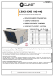
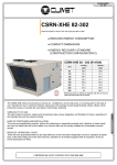
HIGH EFFICIENCY PACKAGED "ROOF TOP" ONLY COOLING AIR CONDITIONER
● REDUCED ENERGY CONSUMPTION
● COMPACT DIMENSIONS
● THERMODYNAMIC HEAT RECOVERY SYSTEM
(CONSTRUCTION CONFIGURATION C)
CSRT-XHE 82 - 302 (R-410A)
Size
Cooling
[kW]
82
33.1
102
37.2
122
46.0
162
52.6
182
65.0
222
74.0
262
93.6
302
103
Performance data are referred to operation with 30% of fresh air intake
and same amount of air exhaust.
VERSATILITY OF USE
The wide range of versions, options and accessories allow unique integration and flexibility of choice, regardless of the
intended use and the external climate.
EASE OF POSITIONING AND INSTALLATION
The units are exceptionally compact, perfect for positioning on especially crowded roofs. Attention to client needs and
care for details has led to the creation of a machine than can be quickly installed and immediately commissioned.
REDUCED OPERATING COSTS
These are now guaranteed thanks to the high efficiency of the innovative refrigeration circuit for operation at partial load,
of the free-cooling and of the heat recovery, standard on all models equipped with air expulsion, of the optional electrostatic air filters.
CERTIFIED QUALITY SYSTEM UNI EN ISO 9001:2008
BT08E006GB-01
The CSRT-XHE series of autonomous roof-top air conditioners, air-air cooling only, is a turning point in this type of unit.
Intended for use in small and medium sized areas with average crowds (supermarkets, stores, offices, small production
areas), it includes the very latest in technology, featuring:
PACKAGED
82 - 302
GENERAL DESCRIPTION
The CSRT-XHE autonomous roof-top air conditioners are highefficiency air-air cooling only units with completely automatic
operation. Based on user settings, the unit provides complete air
treatment through ventilation, filtering, cooling, complete or partial
addition of fresh air, possibility to control humidity. These machines
are extremely compact and resistant to atmospheric agents, suitable
for outdoor installation on a flat roof, on a platform or on the ground.
The distribution of treated air (to be handled by the client) takes
place via supply and return ducts and suitable distribution devices
such as air outlets or nozzles. They are therefore perfect for air
conditioning of medium-volume rooms with average traffic, such as
commercial surfaces, offices, small production areas.
VERSATILE POSITIONING: ON FLAT ROOF, ON
PLATFORM ON GROUND
VERSATILITY OF USE
The wide range of models and the possibility to choose the
constructive configurations make it possible to select the product that
is best suited to the needs of each installation and to integrate the
unit into various architectonic contexts. The selection of accessories
completes the possibility to customize the product according to the
needs of the client.
EXTREME COMPACTNESS
The original layout of the sections that make up the machine
substantially reduces its footprint, making it easier to position and
leaving more space available for parking, additional equipment
rooms or other uses. This also reduces the time required for the
positioning of the ducts on the various sides of the unit, since its
great compactness allows its complete rotation (which is very difficult
with traditional units with in-line extension).
REDUCTION OF CONSUMPTION AND OPERATING COSTS
BT08E006GB-00
The roof-top units of the XHE series were created with the objective
of always operating at maximum energy savings through an
extremely intelligent and advanced control of power provided only
when it is needed, especially during frequent conditions of operation
at partial load. The use of the free-cooling device and the adoption of
thermodynamic recovery on the expelled air make it possible to
further reduce operating costs. Since ventilation represents one of
the greatest factors of energy consumption, special attention has
been given to the efficiency of the ventilation system through careful
selection of components and limitations of internal pressure drops.
The limitation of the emissions of carbon dioxide and respect for the
environment are guiding thoughts of Clivet which, through the
implementation of modern technical solutions, pursues the reduction
of energy consumption.
EASY MAINTENANCE
The entire series is designed with highly reliable industrial
components that are easily accessible and available if maintenance
is required. It is also equipped with self-diagnosis and safety devices
that ensure its proper operation while at the same time protecting
users.
2
APPLICATION EXAMPLES
PACKAGED
82 - 302
STANDARD UNIT SPECIFICATIONS
CB - PRINCIPLE OF OPERATION OF STANDARD UNIT (VERSION B)
The standard constructional configuration, called version B, allows automatic control of supply and return air flow
and the intake of fresh air for required refreshing by means of a manually operated shutter.
The version with optional setups is equipped with shutters with a servo-motor for constant adjustment of the
refresh air mixture:
operation with a fixed percentage of refresh air with opening or closing of the shutter by means of an actuator
(ON-OFF) which intervenes when ventilation is active (optional);
operation with variable percentage of refresh air with opening and closing of the shutters by means of modulating
actuators driven by the signal of the air quality probe (optional).
EXHAUST AIR
RETURN
FRESH AIR
SUPPLY
FRESH AIR
CC - OPTIONAL VERSION WITH EXPULSION, HEAT RECOVERY AND FREE-COOLING
When the machine is in optional constructive configuration (called version C), it allows automatic management of
the supply and return air flows, and the intake of fresh air for required refreshing. In addition, it is capable of
expelling the return air from the served room by means of dedicated fans and to recover the energy of the
expelled air. The automatic adjustment of the shutters allows operation of the unit:
- with full recirculation
- with a mixture of return air and fresh air
- with a mixture of return air and re-circulation air and expulsion of a part of the return air
- with all fresh air and total expulsion of return air (total free-cooling).
BT08E006GB-00
N.B.: the expulsion fan serves to draw only part of the return air flow and expel it from the machine. This fan is not
expected to overcome the pressure drops of the return duct. The control of supply and return air flows is handled
only by the treatment zone fan. Therefore this fan must ensure static pressure to overcome the supply and return
pressure drops. Refer to the maximum static pressure value in the general technical data tables).
EXHAUST AIR
RETURN
+
FRESH AIR
SUPPLY
-
FRESH AIR
3
PACKAGED
82 - 302
PLUG FANS EC
The units are equipped in supply and in expulsion with radial
plug fans with reversed blades directly coupled to highperformance brushless DC motors.
The plug fans differ from traditional centrifugal fans in that
there are no belts or pulleys. This results in increased
efficiency and makes it possible to dynamically vary the
speed. You can change the number of fan revs directly from
the keypad to adapt the static pressure to the pressure drop of
the system.
NEW GENERATION OF AXIAL FANS FOR THE EXTERNAL SECTION
The need for continuous improvement in machine performance has led to collaboration with specialized European
laboratories for the development of more efficient axial fans. The result of this research has made it possible to
develop an innovative winglet-type profile at the end of the blade. The adoption of the new profiles has made it
possible to obtain substantial results in noise limitation, with an average reduction of 6 dB(A), and energy savings,
with a reduction in consumption of 10%.
TRADITIONAL FAN
FAN WITH WINGLETS
AIR FILTERING
Standard units are standard equipped with a suitable filtering
section composed of pleated filters, class G4, with an ample
surface. They are easily accessible for periodic maintenance.
BT08E006GB-00
OUTSIDE TEMPERATURE PROBE
The measurement of the temperature of outside air is an
essential parameter of heat adjustment. It takes place via a
probe located in a special compartment that connects the
external environment and the return duct (always in negative
pressure). Clivet has chosen this solution to ensure correct
measurement of temperature since the probe is constantly in
contact with a minimum flow of air. On request, the
temperature probe can be integrated with the optional humidity
probe).
INTAKE DUCT
FRESH AIR
OUTSIDE TEMPERATURE PROBE
4
PACKAGED
82 - 302
ELECTRONIC EXPANSION VALVE
The electronic expansion valve is an essential component of the
refrigerant circuit. It offers a number of advantages as compared to
the traditional thermostatic valve. These include:
- reduction of overheating temperature (greater efficiency of
refrigerant circuit)
- improved compressor working conditions (COP optimized)
- reduction of output temperature of the compressor
- reduction of pressure at condenser (less energy absorbed by
compressors)
- adaptation to all load conditions and transitories without causing
swinging at partial loads
All this aids in increasing the efficiency of the load for any thermal
load condition and to extend the life cycle.
LOW EFFICIENCY
DANGER OF BREAKAGE OVERHEATING
HIGH EFFICIENCY
OPTIMAL OPERATION
LOW EFFICIENCY
P = Provided Power Variation
EEV= Electronic valve
TEV = Thermostatic valve
DANGER OF BREAKAGE PRESENCE OF LIQUID
UPDATED ELECTRONIC CONTROL
BT08E006GB-00
The operation of the unit is fully automatic thanks to the Clivet Talk
electronic adjustment system. This is a modular device, of automatic
origins, with high speed and reliability and control logic specifically
designed for this type of product. The user interface is easy to use.
This allows better use of available resources, extending the life cycle
of the components and thus reducing maintenance costs. With the
micro-processor keypad, it is possible to perform daily/weekly
programming of the set-point, as well as start-up or shutdown of the
machine. The unit can also be connected to supervision systems
using clean contacts or by serial with the standards of
communication most commonly available on the market.
5
PACKAGED
82 - 302
VERY HIGH EFFICIENCY AT PARTIAL LOAD
In air conditioning projects, the choice of the unit is made based on the maximum load of the room to be served.
In practice, over the course of the year these operating conditions are limited to short periods of time, whereas
operation at partial loads is the actual normal operating condition. The need to adapt the power provided to the
load requested becomes essential in limiting energy consumption. This is why we have decided to couple two
scroll compressors of different power on a single refrigeration circuit, thus obtaining very high efficiency. The
electronic control that the machine is equipped with divides compressor operation into three steps of power (1/3,
2/3, 3/3). This limits the oscillation of the air temperature, and provides perfect adaptation to partial load, offering
substantial energy savings.
8
7
6
EER
5
4
3
2
1
0
(1)
(2)
(3)
SELF-ADAPTABILITY
BT08E006GB-00
SET POINT [°C]
Thanks to the automatic adjustment of the operating parameters based on the system load conditions, the unit is
capable of optimizing its own efficiency, reducing the resulting consumption and extending the life-cycle of the
components. The temperature range to be maintained in the room can be set by the user (manual set-point) or
managed by the machine logic (automatic set-point). When AUTOMATIC,mode is set, the working set-points are
calculated automatically and dynamically by the thermal control device based on the outside temperature and
other parameters set during commissioning of the machine, thus avoiding thermal shock between the treated
room and the exterior.
COOLING SET POINT
28
ZO
AD
DE
22.5
THE GRAPH SHOWS THE TREND OF THE
CURVES OF THE HOT SET POINT (BOTTOM
LINE) AND OF THE COLD SET POINT (UPPER
LINE) BASED ON THE OUTSIDE TEMPERATURE. THE HIGHLIGHTED TEMPERATURE VALUES ARE THOSE SET AS DEFAULT, BUT
THEY MAY BE CHANGED ACCORDING TO
CLIENT NEEDS.
NE
21.5
ZONE
DEAD
19
HEATING SET POINT
5
20
24
35
OUTDOOR AIR TEMPERATURE °C
6
PACKAGED
82 - 302
DEMAND LIMIT
AVAILABLE POWER
The Demand Limit function is a logic that controls the machine's resources dedicated to limiting the input power
from the electrical mains (for example when there are special agreements between the user and the operator of
the electrical mains) or to selecting the thermal resources to be used based on special needs of the client. The
Demand Limit device can control and manage the available steps of thermal power by means of the receipt of an
external analogue signal, 0-10V/4-20mA. The control logic does not act on the ventilation which is therefore
always ensured. The greater the input signal to the Demand Limit, the less the thermal power available for the
system. In the extreme condition of pilot signal at 100%, the system can also shut off the last power step.
AS THE DEMAND LIMIT SIGNAL INCREASES,
THE POWER STEPS ARE GRADUALLY DISABLED. WHEN THE SIGNAL IS AT 100%, ALL
AVAILABLE RESOURCES ARE DISABLED.
SIGNAL 0-10V DC
ACTIVE ENERGY RECOVERY OF EXPELLED AIR (ONLY FOR C VERSION)
The energy contained in the expelled air is recovered by forcing the air flow to pass
through the external packaged finned heat exchanger. This makes it possible to
reduce the electrical energy absorbed by the compressors, to increase the overall
efficiency of the unit and to extend its operating limits. This thermodynamic recovery
system does not increase electrical energy consumption for ventilation, as instead
happens for recovery with crossed or rotating flows. Greater use of electricity,
caused by the enormous pressure drops on the air side in recovery systems with
crossed or rotating flows, often nullifies the amount of energy recovered and even
exceeds it in some cases.
THERMAL FREE COOLING (ONLY FOR C VERSION)
BT08E006GB-00
As soon as external conditions allow it, the unit is capable of automatically activating
free-cooling mode, which, by keeping the compressors off and drawing in suitably
filtered fresh air, cools the served room. The fresh air flow can be varied based on
actual needs. This operating mode is especially useful in spring and autumn or with
high ambient loads. It allows substantial reduction of the unit's energy consumption
and wear of the compressors.
7
PACKAGED
82 - 302
STANDARD UNIT SPECIFICATIONS
COMPRESSOR
scroll compressor complete with: overload thermal protection, high refrigerant
discharge temperature, rubber antivibration mounts, oil charge.
A oil heater is automatically switched on at the compressor shut-down to prevent oil dilution by the refrigerant.
The compressors are connected in tandem on a single refrigerator circuit.
They have bi-phase equalization of the oil and are equipped with cut-off bibcocks
STRUCTURE
The basement is assembled with a painted galvanized steel frame. The internal structure is made of “ALUZINK” bent galvanized steel . The alloy that protects the Aluzink allow an excellent corrosion proofing thanks to the galvanic
protection typical of the combination aluminium-zinc.
PANELLING
Panels of the compressor panel in steel sheet metal, painted using polyester
powders, colour RAL 9001 and covered on the inside with ashlared soundabsorbent material.
Sandwich panels in the air treatment section with dual walls in steel sheet
metal with polyurethane insulation (40 kg/m3), thickness of outer sheet metal
6/10 mm galvanized and painted using polyester powders colour RAL 9001,
polyurethane thickness with thermal conductivity coefficient 0.022W/mK, thickness of internal sheet metal 5/10 mm hot galvanized. The panel is also
provided with a PVC profile for thermal insulation and a EPDM rubber gasket
that ensures the hermetic seal.
All panelling can easily be removed to allow complete accessibility to internal
components.
INTERNAL EXCHANGER
direct expansion finned exchanger, made from copper pipes in staggered rows
and mechanically expanded to the fin collars. The fins are made from aluminium with a corrugated surface and adequately distanced to ensure the maximum heat exchange efficiency.
EXTERNAL EXCHANGER
direct expansion finned exchanger, made from copper pipes in staggered rows
and mechanically expanded to the fin collars. The fins are made from aluminium with a corrugated surface and adequately distanced to ensure the maximum heat exchange efficiency.
FAN
Internal section
Plug fans without scroll with reverse blades driven by electronically-controlled
"brushless" dc motors with direct coupling. No transmission sizing is needed.
External section
Helical fans with sickle-shaped blades with "Winglets" at the end, coupled
directly to a three phase electric external rotor motor with thermal protection
incorporated in version IP 54. Housed in aerodynamically shaped nozzles to
increase efficiency and minimize noise levels. They are fitted with protective
safety guard grilles.
REFRIGERANT CIRCUIT
The circuit is complete with:
- refrigerant charge
- sight glass with moisture indicator
- high pressure switch
- low pressure switch
- filter dryer
- electronic expansion valve
- liquid receiver
- high pressure safety valve
- low pressure safety valve
BT08E006GB-00
FILTRATION
fresh air intake side
Pleated filter for greater filtering surface, made up of galvanized plate frame
with galvanized and electric-welded protective mesh, and regenerable filtering
media made from polyester fibre sized with synthetic resins. G4 efficiency
according to CEN-EN 779 standard (Eurovent class EU4/5 - average efficiency
90.1% ASHRAE 52-76 Atm). Self-extinguishing (resistance to fire class 1 - DIN
53438).
ambient air suction side
Pleated filter for greater filtering surface, made up of galvanized plate frame
with galvanized and electric-welded protective mesh, and regenerable filtering
media made from polyester fibre sized with synthetic resins. G4 efficiency
according to CEN-EN 779 standard (Eurovent class EU4/5 - average efficiency
90.1% ASHRAE 52-76 Atm). Self-extinguishing (resistance to fire class 1 - DIN
53438).
TRAY
condensate collecting tray in aluminum alloy 1050 H24 with anti-condensate
insulation, welded and equipped with threaded discharge coupling
8
ELECTRICAL PANEL
The electrical panel is positioned inside the units, with access through a swing
door that is opened by a special key.
The Power Section includes:
- main door lock isolator switch
- circuit breaker to protect auxiliary circuit
- compressor power supply remote control switch
- fan motor thermal protections of internal section and external section
- compressor circuit breaker
Microprocessor control section:
- treated air temperature control
- daily, weekly programmer of temperature setpoint and unit on/off
- compressor overload protection and timer
- self-diagnosis system with immediate display of the error code
- demand limit
- clean contacts for remote ON-OFF, cumulative alarm, fan status, compressor
status, summer/winter mode
- control keypad, including:
display to indicate operating status and mode
display of the set values and the error codes
menu button to display the parameter index
alarm button to display the list of alarms
unit operation or ventilation only selection button
On/Off and manual reset button for overload device activation
UP and DOWN buttons to increase and decrease the values
C VERSION
Exhaust fan
Plug fan with no screw, reversed blades, driven by a brushless DC motor with
electronic control directly coupled. No transmission sizing is required.
ACCESSORIES
- copper / copper evaporator coils
- copper / copper condenser coils
- water heating coil
- modulating three-way valve
- hot gas re-heating coil
- Copper / copper hot gas re-heating coil
- electrode boiler steam humidifier
- water to waste evaporating wet-deck humidifier
- Electric heaters.
- Heating module with modulating condensing gas burner
- Air quality sensor for CO2 p.p.m. control
- Air quality sensor for CO2 and VOC p.p.m. control
- constant value flow rate adjuster
- bag filters section F7 class
- High efficiency electrostatic filters additional section
- high and low pressure gauges
- Active winter thermodynamic recovery on expelled air
- serial port RS485 with MODBUS protocol
- serial port RS485 with LONWORK protocol
- phase monitor
- power factor correction capacitors (cosfi > 0.9)
- Device for reducing consumption of the outdoor section variable speed fans
(phase-cut)
- Variable fan speed control for operation at low ambient temperature
ECOBreeze
- differential pressure switch for dirty air filters
- free-cooling with independent comparison of temperature and absolute humidity (only for C version)
- smoke detector
- Remote control with remote microprocessor control (separately supplied
accessories)
- Rubber antivibration mounts (separately supplied accessories)
TEST
Unit manufactured according to the ISO 9001 quality standards and subject to
functional testing at the end of the production line
PACKAGED
82 - 302
AIR FLOW: STANDARD
GENERAL TECHNICAL SPECIFICATIONS
Size
82
102
122
162
182
222
262
302
33.1
23.4
8
4.13
37.2
26.6
9.6
3.89
46
34.3
11.8
3.91
52.6
37.8
13.5
3.91
65
46.1
15
4.35
74
54
18.5
4
93.6
66.7
20.2
4.64
102.9
73.7
23.5
4.38
Scroll
2
2
1
Scroll
2
3
1
Scroll
2
2
1
Scroll
2
3
1
Scroll
2
3
1
Scroll
2
3
1
Scroll
2
3
1
Scroll
2
2
1
RAD
1
450
CC
1500
1.1
280
RAD
1
500
CC
1700
2.7
600
RAD
1
500
CC
2220
2.7
450
RAD
1
560
CC
2500
3.1
520
RAD
1
630
CC
3060
3.2
450
RAD
1
630
CC
3610
3.2
370
RAD
2
500
CC
4440
2.7
460
RAD
2
560
CC
5000
3.1
510
kW
RAD
1
450
CC
1.1
RAD
1
450
CC
1.1
RAD
1
450
CC
1.1
RAD
1
450
CC
1.1
RAD
1
500
CC
2.7
RAD
1
500
CC
2.7
RAD
1
630
CC
3.2
RAD
1
630
CC
3.2
Nr
mm
rpm
l/s
kW
AX
1
630
1330
3611
1.1
AX
1
630
1330
3611
1.1
AX
1
800
660
4440
1.3
AX
1
800
880
5700
2
AX
2
710
900
6670
1
AX
2
710
900
6670
1
AX
2
800
880
11400
2
AX
2
800
880
11400
2
V
400/3/50
400/3/50
400/3/50
400/3/50
400/3/50
400/3/50
400/3/50
400/3/50
COOLING
Cooling capacity
Sensible capacity
Compressor power input
EER
COMPRESSOR
1
1
1
1
Type of compressors
No. of Compressors
Std Capacity control steps
Refrigerant circuits
AIR HANDLING SECTION FANS (OUTLET)
2
Type of fans
Number of fans
Fan diameter
Type of motor
Air flow
Installed unit power
Max outside static pressure
FANS (EXPULSION)
3
kW
kW
kW
Nr
Nr
Nr
Nr
mm
4
Type of fans
Number of fans
Fan diameter
Type of motor
Installed unit power
EXTERNAL SECTION FANS
3
Type of fans
Number of fans
Fan diameter
Fan RPM
Standard air flow
Installed unit power
POWER SUPPLY
5
l/s
kW
Pa
Nr
mm
Standard power supply
Performance data are referred to operation with 30% of fresh air intake and same amount of air exhaust. (construction configuration C)
(1) Ambient temperature 27°C/19.5 WB
external exchanger air intake 35°C
EER referred only to compressors
(2) SCROLL = scroll compressor
(3) RAD = radial ventilation
(4) Net outside static pressure to win the outlet and intake onboard pressure drops
(5) AX = axial-flow fan
OPERATING LIMITS (COOLING)
30
Ta (W.B.)
25
(2)
20
(1)
15
BT08E006GB-00
THE LIMITS ARE INDICATIVE AND HAVE BEEN CALCULATED CONSIDERING:
- VALUES GENERAL AND NOT SPECIFICATIONS,
- STANDARD AIR FLOW-RATE,
- NON-CRITICAL POSITIONING AND CORRECT USE OF THE UNIT,
- OPERATION AT FULL LOAD
WITH UNIT OPERATING IN INTAKE OF OUTSIDE AIR CALCULATE THE TEMPERATURES OF MIXES WHICH ARE GENERATED FROM THE EXCHANGERS' INLET TO
KNOW THE LIMITS.
TO = TEMPERATURE OF AIR ENTERING THE EXTERNAL EXCHANGER D.B.(°C)
DB = DRY BULB
TA = INTERNAL EXCHANGER INLET AIR TEMPERATURE W.B. (°C)
WB = WET BULB
(1) THE DASHED AREA REFERS TO THE FIELD OF UNITS OPERATION
STANDARD
(2) IN THE CROSS-HATCHED AREA IS IDENTIFIED THE UTILITY FIELD FOR UNIT
WITH LOW TEMPERATURE DEVICE
10
5
0
5
10
15
20
25
30
35
40
45
50
To (D.B.)
9
PACKAGED
82 - 302
CONSTRUCTIONAL CONFIGURATION: MIXING BOX FOR RECYCLE /FRESH AIR (B)
ELECTRICAL DATA
Size
82
102
122
162
182
222
262
302
10.2
9.8
2.5
2.2
25.2
14.3
9.8
2.5
4.3
31.4
14.3
14.3
2.3
4.3
35.7
16.4
15.2
4.1
4.9
41.1
22.6
15.2
2.5
4.9
48.2
30.6
15.2
2.5
4.9
56.2
30.6
22.6
4.1
4.3
70.5
30.6
30.6
4.1
4.9
79.7
L.R.A. - Compressor 1
A
64
A
64
L.R.A. - Compressor 2
F.L.I. FULL LOAD POWER INPUT AT MAX ADMISSIBLE CONDITION
101
64
101
101
111
95
118
95
173
95
173
118
173
173
F.L.I. - Compressor 1
F.L.I. - Compressor 2
F.L.I. - Single External Fan
F.L.I. - Single supply fan
F.L.I. - Total
M.I.C. MAXIMUM INRUSH CURRENT
8.3
5.9
1.1
2.7
18.3
8.3
8.3
1.2
2.7
20.8
10.1
8.9
1.9
3.1
24.3
13.2
8.9
1.1
3.2
27.7
17
8.9
1.1
3.2
31.5
17
13.2
1.9
2.7
39.7
17
17
1.9
3.1
44.3
118.1
122.4
135.7
143.6
198.6
212.9
222.1
F.L.A. - FULL LOAD CURRENT AT MAX ADMISSIBLE CONDITIONS
F.L.A. - Compressor 1
F.L.A. - Compressor 2
F.L.A. - Single External Fan
F.L.A. - Single supply fan
F.L.A. - Total
L.R.A. LOCKED ROTOR AMPERES
M.I.C. - Value
A
A
A
A
A
kW
kW
kW
kW
kW
6
5.9
1.1
1
14.3
A
79
Data referred to standard units.
power supply: 400/3/50 Hz +/-6%
voltage unbalance: max 2 %
Values not including accessories
CONSTRUCTIONAL CONFIGURATION: FREE COOLING VERSION WITH EXTRACT/RECIRCULATED/FRESH AIR INTAKE BOX (C)
ELECTRICAL DATA
Size
82
102
122
162
182
222
262
302
10.2
9.8
2.5
2.2
2.2
27.4
14.3
9.8
2.5
4.3
2.2
33.6
14.3
14.3
2.3
4.3
2.2
37.9
16.4
15.2
4.1
4.9
2.2
43.3
22.6
15.2
2.5
4.9
4.3
52.5
30.6
15.2
2.5
4.9
4.3
60.5
30.6
22.6
4.1
4.3
4.9
75.4
30.6
30.6
4.1
4.9
4.9
84.6
L.R.A. - Compressor 1
A
64
A
64
L.R.A. - Compressor 2
F.L.I. FULL LOAD POWER INPUT AT MAX ADMISSIBLE CONDITION
101
64
101
101
111
95
118
95
173
95
173
118
173
173
F.L.I. - Compressor 1
F.L.I. - Compressor 2
F.L.I. - Single External Fan
F.L.I. - Single supply fan
F.L.I. – Single exhaust air fan
F.L.I. - Total
M.I.C. MAXIMUM INRUSH CURRENT
8.3
5.9
1.1
2.7
1
19.3
8.3
8.3
1.2
2.7
1
21.8
10.1
8.9
1.9
3.1
1
25.3
13.2
8.9
1.1
3.2
2.7
30.4
17
8.9
1.1
3.2
2.7
34.2
17
13.2
1.9
2.7
3.2
42.9
17
17
1.9
3.1
3.2
47.5
120.3
124.6
137.9
147.9
202.9
217.8
227
F.L.A. - FULL LOAD CURRENT AT MAX ADMISSIBLE CONDITIONS
F.L.A. - Compressor 1
F.L.A. - Compressor 2
F.L.A. - Single External Fan
F.L.A. - Single supply fan
F.L.A. - Single exhaust air fan
F.L.A. - Total
L.R.A. LOCKED ROTOR AMPERES
M.I.C. - Value
A
A
A
A
A
A
kW
kW
kW
kW
kW
kW
6
5.9
1.1
1
1
15.3
A
81.2
Data referred to standard units.
power supply: 400/3/50 Hz +/-6%
voltage unbalance: max 2 %
Values not including accessories
ELECTRICAL INPUT OF OPTIONAL COMPONENTS
To obtain the electrical input of the unit including accessories, add the standard data in Electrical Data table to those for the selected accessories.
BT08E006GB-00
SIZE
10
F.L.A. FULL LOAD CURRENT
F.L.A. EH07 - 3 kW electric heaters
F.L.A. EH10 - 6 kW electric heaters
F.L.A. EH12 - 9 kW electric heaters
F.L.A. EH14 - 12 kW electric heaters
F.L.A. EH17 - 18 kW electric heaters
F.L.A. EH20 - 24 kW electric heaters
F.L.A. EH24 - 36 kW electric heaters
F.L.A. HSE3 - Electrode boiler steam humidifier from 3 kg/h
F.L.A. HSE5 - Electrode boiler steam humidifier from 5 kg/h
F.L.A. HSE8 - Electrode boiler steam humidifier from 8 kg/h
F.L.A. HSE9 - Electrode boiler steam humidifier from 15 kg/h
F.L.A. FES - High efficiency H10 electrostatic air filter
F.L.I. ABSORBED POWER
F.L.I. EH07 - 3 kW electric heaters
F.L.I. EH10 - 6 kW electric heaters
F.L.I. EH12 - 9 kW electric heaters
F.L.I. EH14 - 12 kW electric heaters
F.L.I. EH17 - 18 kW electric heaters
F.L.I. EH20 - 24 kW electric heaters
F.L.I. EH24 - 36 kW electric heaters
F.L.I. HSE3 - Electrode boiler steam humidifier from 3 kg/h
F.L.I. HSE5 - Electrode boiler steam humidifier from 5 kg/h
F.L.I. HSE8 - Electrode boiler steam humidifier from 8 kg/h
F.L.I. HSE9 - Electrode boiler steam humidifier from 15 kg/h
F.L.I. FES - High efficiency H10 electrostatic air filter
82
102
122
162
182
222
262
302
A
A
A
A
A
A
A
A
A
A
A
A
4,8
8,7
13
3,2
8,7
8,7
0,6
4,8
8,7
13
3,2
8,7
8,7
0,6
8,7
13
17,3
26
3,2
8,7
8,7
16.0
1,1
8,7
13
17,3
26
3,2
8,7
8,7
16.1
1,1
17,3
26
34,6
3,2
8,7
8,7
16.2
1,5
17,3
26
34,6
3,2
8,7
8,7
16.2
1,5
26
34,6
52
3,2
8,7
8,7
16.2
1,5
26
34,6
52
3,2
8,7
8,7
16.2
2,2
kW
kW
kW
kW
kW
kW
kW
kW
kW
kW
kW
kW
3,2
6
9
-
3,2
6
9
-
2,3
6,0
6,0
0,15
2,3
6,0
6,0
0,15
6
9
12
18
2,3
6,0
6,0
11,3
0.25
6
9
12
18
2,3
6,0
6,0
11,3
0.25
12
18
24
2,3
6,0
6,0
11,3
0.33
12
18
24
2,3
6,0
6,0
11,3
0.33
18
24
36
2,3
6,0
6,0
11,3
0.33
18
24
36
2,3
6,0
6,0
11,3
0.5
PACKAGED
82 - 302
SOUND LEVELS
Sound Power Level (dB)
Size
Octave band (Hz)
Sound
pressure
level
Sound
power level
63
125
250
500 1000 2000 4000 8000
dB(A)
dB(A)
82
83
78
80
76
76
73
65
55
62
80
102
83
76
80
76
78
72
65
55
62
80
122
86
80
83
78
78
73
67
57
63
82
162
86
79
83
81
80
72
67
59
65
83
182
88
89
90
82
80
76
69
67
67
86
222
88
89
90
82
80
76
71
63
67
86
262
90
89
89
82
81
78
72
67
68
87
302
90
83
89
85
85
81
74
69
69
88
The sound levels are referred to units working at full load in nominal
conditions. The sound pressure level is referred at a distance of 1 m.
from the ducted unit surface working in free field conditions.External
static pressure 50 Pa.
(standard UNI EN ISO 3744)
Please note that when the unit is installed in conditions other than
nominal test conditions (e.g. near walls or obstacles in general), the
sound levels may undergo substantial variations.
PRESSURE DROPS OF OPTIONAL COMPONENTS
The value of static pressure available on the supply and return duct is obtained by subtracting from the available
net maximum pressure (see general table of technical data) the pressure drops of any accessories.
SIZE
PRESSURE DROP
CHW2 2 rows hot water coil
CPHG Hot gas re-heating coil
GH01 Gas re-heating module from 54 kW
GH02 Gas re-heating module from 72 kW
GH03 Gas re-heating module from 96 kW
GH05 Gas re-heating module from 150 kW
F7
High efficiency F7 air filter
FES
High efficiency H10 electrostatic air filter
HWS Water to waste evaporating wet-deck humidifier
Pa
Pa
Pa
Pa
Pa
Pa
1 Pa
Pa
Pa
82
102
122
162
182
222
262
302
23
10
60
90
15
10
28
15
70
100
20
15
32
15
60
60
95
20
15
38
20
70
70
100
25
20
34
10
60
60
90
15
10
47
15
70
70
95
20
15
36
10
60
60
95
15
10
46
20
70
70
100
25
20
BT08E006GB-00
The values shown are to be considered approximate for units operating power in normal use with standard air flow rate.
(1)Pressure drops with filters with average dirtiness
11
PACKAGED
82 - 302
AIR FLOW: STANDARD
Size
82
102
122
162
182
222
262
302
1500
280
1700
600
2220
450
2500
520
3060
450
3610
370
4440
460
5000
510
AIR HANDLING SECTION FANS (OUTLET)
Air flow
Max outside static pressure
l/s
Pa
COOLING PERFORMANCE
Size
82
102
122
162
BT08E006GB-00
182
222
262
12
Ta
(°C)
DB/WB
OUTDOOR AIR TEMPERATURE °C
25
30
32
35
40
44
kWf
kWe
kWs
kWf
kWe
kWs
kWf
kWe
kWs
kWf
kWe
kWs
kWf
kWe
kWs
kWf
kWe
kWs
22 / 16
30.9
6.24
22.7
30.9
7.04
22.1
30.9
7.36
21.8
31.0
7.84
21.4
31.2
8.65
20.7
31.5
9.30
20.1
24 / 17
31.4
6.33
24.3
31.5
7.11
23.6
31.5
7.42
23.3
31.6
7.89
22.9
31.8
8.69
22.2
32.0
9.33
21.6
26 / 19
32.7
6.47
24.1
32.7
7.23
23.5
32.7
7.53
23.2
32.7
8.00
22.8
32.8
8.78
22.1
32.9
9.41
21.5
27 / 19.5
33.0
6.50
24.8
33.0
7.26
24.1
33.0
7.56
23.9
33.0
8.02
23.5
33.1
8.80
22.8
33.1
9.43
22.2
28 / 21
34.1
6.58
23.7
34.0
7.34
23.1
34.0
7.64
22.8
33.9
8.10
22.4
33.8
8.88
21.7
33.6
9.51
21.2
30 / 22
34.9
6.62
24.9
34.8
7.38
24.2
34.7
7.69
23.9
34.5
8.15
23.5
34.2
8.94
22.8
33.9
9.57
22.3
22 / 16
34.8
7.48
25.5
35.1
8.33
24.8
35.2
8.69
24.5
35.3
9.25
24.0
35.4
10.2
23.3
35.3
11.1
22.7
24 / 17
35.4
7.56
27.1
35.6
8.43
26.4
35.7
8.79
26.1
35.8
9.35
25.7
35.9
10.3
25.0
35.9
11.1
24.4
26 / 19
36.8
7.73
27.2
36.8
8.61
26.5
36.8
8.98
26.2
36.9
9.53
25.7
37.0
10.5
25.0
37.1
11.3
24.5
27 / 19.5
37.2
7.77
28.0
37.2
8.66
27.3
37.2
9.02
27.0
37.2
9.57
26.6
37.3
10.5
25.9
37.5
11.3
25.3
28 / 21
38.4
7.89
26.7
38.3
8.78
26.0
38.3
9.14
25.7
38.3
9.69
25.3
38.4
10.6
24.6
38.4
11.4
24.0
30 / 22
39.2
7.97
27.8
39.2
8.86
27.1
39.2
9.22
26.8
39.2
9.77
26.4
39.1
10.7
25.7
39.1
11.5
25.1
22 / 16
43.2
9.27
32.3
43.0
10.3
31.4
43.0
10.7
31.1
43.1
11.4
30.5
43.4
12.6
29.6
43.8
13.5
28.8
24 / 17
43.9
9.39
34.7
43.9
10.4
33.8
43.9
10.9
33.4
43.9
11.5
32.9
44.1
12.7
32.0
44.4
13.6
31.3
26 / 19
45.6
9.60
34.8
45.6
10.6
34.0
45.6
11.1
33.7
45.6
11.7
33.1
45.6
12.9
32.3
45.5
13.8
31.6
27 / 19.5
46.1
9.65
36.0
46.1
10.7
35.1
46.1
11.1
34.8
46.0
11.8
34.3
46.0
12.9
33.4
45.9
13.9
32.7
28 / 21
47.7
9.79
33.9
47.5
10.8
33.0
47.4
11.3
32.7
47.3
11.9
32.1
47.0
13.1
31.3
46.9
14.1
30.5
30 / 22
48.9
9.87
34.6
48.4
10.9
33.7
48.3
11.4
33.3
48.1
12.0
32.7
47.8
13.2
31.8
22 / 16
49.4
10.7
36.9
49.4
11.8
35.8
49.4
12.3
35.4
49.5
13.1
34.7
49.7
14.4
33.7
50.0
15.5
32.8
24 / 17
50.5
10.8
39.1
50.3
11.9
38.0
50.3
12.4
37.6
50.4
13.2
37.0
50.5
14.5
35.9
50.8
15.6
35.1
26 / 19
52.4
11.0
38.7
52.2
12.2
37.7
52.2
12.7
37.3
52.1
13.4
36.6
52.2
14.7
35.6
52.4
15.8
34.8
27 / 19.5
52.9
11.1
39.8
52.7
12.2
38.8
52.6
12.7
38.4
52.6
13.5
37.8
52.7
14.8
36.7
52.8
15.9
35.9
28 / 21
54.1
11.2
38.3
54.1
12.4
37.2
54.1
12.9
36.8
54.1
13.6
36.2
54.1
14.9
35.2
54.1
16.0
34.4
30 / 22
54.8
11.3
40.4
55.0
12.5
39.4
55.0
13.0
39.0
55.0
13.7
38.3
55.0
15.0
37.3
55.0
16.1
36.5
22 / 16
60.9
11.9
45.6
61.5
13.2
44.2
61.6
13.7
43.6
61.8
14.5
42.8
61.7
15.9
41.4
61.4
17.1
40.3
24 / 17
62.1
12.0
48.3
62.5
13.3
46.9
62.6
13.9
46.4
62.6
14.7
45.5
62.3
16.1
44.1
61.8
17.2
43.0
26 / 19
64.6
12.3
47.5
64.7
13.6
46.1
64.7
14.1
45.6
64.5
14.9
44.8
63.9
16.3
43.4
63.1
17.5
42.3
27 / 19.5
65.2
12.4
48.8
65.3
13.6
47.5
65.2
14.2
46.9
65.0
15.0
46.1
64.4
16.3
44.8
63.6
17.5
43.7
28 / 21
67.2
12.5
47.5
67.1
13.8
46.2
67.0
14.3
45.7
66.7
15.1
44.9
66.0
16.5
43.6
65.0
17.6
42.5
30 / 22
68.5
12.6
51.5
68.4
13.9
50.2
68.3
14.4
49.7
68.0
15.2
48.9
67.2
16.5
47.7
22 / 16
69.0
14.7
51.9
69.6
16.3
50.6
69.8
16.9
50.0
70.1
17.9
49.2
70.6
19.7
47.9
70.9
21.2
46.8
24 / 17
70.5
14.8
55.1
70.7
16.4
53.8
70.8
17.1
53.3
71.0
18.1
52.6
71.3
19.9
51.3
71.7
21.4
50.3
26 / 19
73.6
15.1
54.8
73.4
16.7
53.5
73.3
17.4
53.1
73.3
18.4
52.3
73.4
20.2
51.1
73.5
21.6
50.1
27 / 19.5
74.3
15.2
56.5
74.1
16.8
55.3
74.1
17.5
54.8
74.0
18.5
54.0
74.0
20.2
52.7
74.0
21.6
51.7
28 / 21
76.4
15.4
54.4
76.5
17.1
53.0
76.4
17.7
52.5
76.3
18.7
51.6
76.1
20.4
50.2
75.7
21.7
49.1
30 / 22
77.8
15.6
57.7
78.1
17.2
56.2
78.2
17.8
55.6
78.1
18.8
54.7
77.7
20.4
53.1
77.1
21.7
51.9
22 / 16
86.2
16.2
65.4
87.2
17.9
63.6
87.5
18.6
62.9
87.9
19.7
61.8
88.4
21.6
59.9
88.6
23.3
58.5
24 / 17
88.2
16.3
69.3
88.9
18.0
67.5
89.2
18.7
66.8
89.5
19.8
65.7
89.8
21.7
63.9
90.0
23.4
62.5
26 / 19
92.0
16.6
68.2
92.5
18.3
66.4
92.7
19.0
65.7
92.8
20.1
64.7
92.6
22.0
62.9
92.3
23.6
61.5
27 / 19.5
92.9
16.7
70.2
93.5
18.4
68.5
93.6
19.1
67.8
93.6
20.2
66.7
93.3
22.1
64.9
92.8
23.7
63.5
28 / 21
95.7
16.9
68.5
96.2
18.5
66.7
96.3
19.2
66.0
96.1
20.3
65.0
95.3
22.2
63.2
94.2
23.9
61.8
30 / 22
97.5
17.0
74.6
98.1
18.6
72.8
98.1
19.3
72.1
97.8
20.4
71.1
96.6
22.4
69.3
95.0
24.0
67.9
Ta = ambient air temperature D.B/W.B
DB = dry bulb
WB = wet bulb
kWf = Cooling capacity in kW
kWe = Compressor power input in kW
kWs = sensible cooling capacity (kW)
not all cooling yields take into account the heat dissipated by the fan motors
PACKAGED
82 - 302
AIR FLOW: STANDARD
COOLING PERFORMANCE
Size
Ta
(°C)
DB/WB
22 / 16
302
OUTDOOR AIR TEMPERATURE °C
25
30
32
35
40
44
kWf
kWe
kWs
kWf
kWe
kWs
kWf
kWe
kWs
kWf
kWe
kWs
kWf
kWe
kWs
kWf
kWe
kWs
95.3
18.8
72.0
96.2
20.7
70.2
96.4
21.6
69.5
96.7
22.9
68.4
97.0
25.4
66.5
97.0
27.6
65.1
24 / 17
97.3
19.0
76.1
98.0
20.9
74.3
98.2
21.7
73.6
98.5
23.1
72.5
98.8
25.6
70.6
99.0
27.8
69.1
26 / 19
101.3
19.4
75.3
101.7
21.2
73.5
101.9
22.1
72.7
102.1
23.4
71.6
102.3
25.8
69.7
102.4
28.0
68.3
27 / 19.5
102.3
19.4
77.5
102.7
21.3
75.6
102.8
22.2
74.8
102.9
23.5
73.7
103.1
25.9
71.9
103.1
28.0
70.4
28 / 21
105.3
19.6
75.1
105.5
21.7
73.2
105.6
22.6
72.5
105.6
23.9
71.3
105.5
26.1
69.5
105.2
27.9
68.0
30 / 22
107.3
19.8
80.1
107.5
22.0
78.2
107.5
22.9
77.5
107.4
24.2
76.3
107.0
26.2
74.5
106.4
27.8
73.0
BT08E006GB-00
Ta = ambient air temperature D.B/W.B
DB = dry bulb
WB = wet bulb
kWf = Cooling capacity in kW
kWe = Compressor power input in kW
kWs = sensible cooling capacity (kW)
not all cooling yields take into account the heat dissipated by the fan motors
13
PACKAGED
82 - 302
AIR FLOW: REDUCED
Size
82
102
122
162
182
222
262
302
1200
430
1360
650
1800
580
2000
580
2500
550
3050
460
3750
580
4150
580
AIR HANDLING SECTION FANS (OUTLET)
Air flow
Max outside static pressure
l/s
Pa
COOLING PERFORMANCE
Size
82
102
122
162
BT08E006GB-00
182
222
262
14
Ta
(°C)
DB/WB
OUTDOOR AIR TEMPERATURE °C
25
30
32
35
40
44
kWf
kWe
kWs
kWf
kWe
kWs
kWf
kWe
kWs
kWf
kWe
kWs
kWf
kWe
kWs
kWf
kWe
kWs
24 / 17
30.1
6.22
21.9
30.2
7.04
21.2
30.2
7.37
21.0
30.2
7.88
20.6
30.3
8.76
19.9
30.3
9.49
19.4
26 / 19
31.4
6.38
21.6
31.3
7.16
21.0
31.3
7.49
20.7
31.3
7.98
20.4
31.4
8.83
19.7
31.4
9.53
19.2
27 / 19.5
31.7
6.42
22.2
31.6
7.20
21.5
31.6
7.52
21.3
31.6
8.01
20.9
31.6
8.84
20.3
31.7
9.54
19.8
28 / 21
32.7
6.51
21.5
32.5
7.29
20.9
32.5
7.61
20.7
32.4
8.09
20.3
32.4
8.90
19.7
32.5
9.57
19.2
30 / 22
33.3
6.56
22.6
33.1
7.36
22.0
33.1
7.67
21.8
33.0
8.15
21.4
33.0
8.95
20.8
33.0
9.59
20.3
32 / 23.5
34.3
6.63
23.1
34.1
7.45
22.5
34.0
7.77
22.3
33.9
8.25
21.9
33.8
9.02
21.3
33.7
9.62
20.9
24 / 17
33.9
7.47
24.6
33.8
8.43
23.9
33.8
8.82
23.7
34.0
9.41
23.3
34.5
10.4
22.6
35.0
11.2
22.1
26 / 19
35.2
7.64
24.3
35.2
8.59
23.6
35.2
8.97
23.4
35.3
9.56
22.9
35.6
10.6
22.3
36.0
11.4
21.7
27 / 19.5
35.6
7.69
25.0
35.5
8.62
24.3
35.6
9.01
24.0
35.6
9.59
23.6
35.9
10.6
22.9
36.1
11.4
22.3
28 / 21
36.7
7.80
24.2
36.6
8.74
23.5
36.6
9.12
23.2
36.6
9.70
22.8
36.6
10.7
22.1
36.6
11.5
21.5
30 / 22
37.4
7.87
25.5
37.4
8.81
24.8
37.4
9.19
24.5
37.3
9.77
24.1
37.1
10.8
23.4
36.9
11.6
22.8
32 / 23.5
38.6
7.97
26.1
38.6
8.91
25.4
38.5
9.29
25.1
38.3
9.87
24.6
37.8
10.8
23.9
37.2
11.6
23.4
24 / 17
42.3
9.27
31.6
42.2
10.4
30.7
42.3
10.8
30.4
42.3
11.5
29.9
42.5
12.7
29.0
42.7
13.7
28.3
26 / 19
43.8
9.47
31.1
43.8
10.5
30.2
43.8
11.0
29.9
43.8
11.7
29.4
43.8
12.9
28.5
43.8
13.9
27.8
27 / 19.5
44.2
9.52
32.0
44.3
10.6
31.1
44.3
11.0
30.7
44.3
11.7
30.2
44.2
12.9
29.3
44.1
13.9
28.6
28 / 21
45.7
9.66
30.9
45.7
10.7
30.0
45.7
11.2
29.6
45.6
11.9
29.1
45.4
13.1
28.2
45.1
14.1
27.4
30 / 22
46.9
9.74
32.6
46.8
10.8
31.7
46.7
11.2
31.3
46.6
11.9
30.8
46.2
13.2
29.9
45.8
14.2
29.2
32 / 23.5
48.8
9.86
33.3
48.6
10.9
32.4
48.4
11.4
32.0
48.2
12.1
31.5
47.5
13.3
30.6
24 / 17
48.1
10.7
35.3
48.1
11.9
34.3
48.1
12.4
33.9
48.3
13.2
33.3
48.6
14.5
32.4
48.9
15.7
31.6
26 / 19
50.1
10.8
35.3
50.0
12.1
34.3
50.0
12.6
33.9
50.0
13.3
33.3
50.0
14.7
32.3
50.1
15.9
31.5
27 / 19.5
50.6
10.9
36.2
50.5
12.1
35.2
50.5
12.6
34.8
50.4
13.4
34.2
50.4
14.8
33.2
50.4
15.9
32.5
28 / 21
52.2
11.1
35.0
52.0
12.3
34.0
51.9
12.8
33.6
51.8
13.5
33.0
51.8
14.9
32.0
51.8
16.1
31.2
30 / 22
53.3
11.2
36.6
53.0
12.4
35.7
52.9
12.9
35.3
52.8
13.7
34.7
52.8
15.0
33.7
52.9
16.2
32.9
32 / 23.5
55.0
11.3
37.2
54.5
12.5
36.2
54.4
13.0
35.8
54.3
13.8
35.3
54.5
15.2
34.3
54.9
16.4
33.6
24 / 17
59.5
12.0
43.7
59.9
13.3
42.5
59.9
13.8
42.0
59.9
14.7
41.2
59.8
16.2
40.0
59.4
17.4
39.0
26 / 19
62.1
12.2
43.9
62.2
13.5
42.6
62.1
14.0
42.1
62.0
14.9
41.3
61.6
16.3
40.0
61.2
17.5
39.0
27 / 19.5
62.7
12.3
45.1
62.8
13.5
43.8
62.7
14.1
43.3
62.6
14.9
42.5
62.2
16.3
41.2
61.6
17.6
40.1
28 / 21
64.7
12.4
43.8
64.7
13.7
42.4
64.6
14.2
41.9
64.4
15.0
41.1
63.8
16.5
39.7
63.1
17.7
38.7
30 / 22
66.0
12.5
45.9
66.0
13.8
44.6
65.9
14.3
44.1
65.7
15.1
43.3
65.0
16.5
41.9
64.1
17.7
40.8
32 / 23.5
68.0
12.6
46.7
68.1
13.9
45.4
68.0
14.5
44.9
67.7
15.3
44.1
66.8
16.7
42.7
24 / 17
68.4
14.7
51.2
68.5
16.4
49.8
68.6
17.1
49.3
68.8
18.2
48.5
69.2
20.1
47.1
69.7
21.7
46.0
26 / 19
71.2
15.0
51.2
71.3
16.7
49.9
71.3
17.4
49.3
71.4
18.5
48.6
71.5
20.3
47.2
71.5
21.8
46.2
27 / 19.5
72.0
15.1
52.5
72.0
16.8
51.3
72.0
17.5
50.7
72.0
18.5
50.0
72.0
20.3
48.7
72.0
21.8
47.6
28 / 21
74.2
15.3
50.6
74.1
17.0
49.3
74.1
17.7
48.8
74.0
18.7
48.1
73.7
20.5
46.8
73.5
21.9
45.8
30 / 22
75.7
15.4
53.1
75.5
17.1
51.8
75.5
17.8
51.3
75.3
18.8
50.6
74.9
20.6
49.3
74.5
22.0
48.3
32 / 23.5
78.0
15.6
53.9
77.7
17.3
52.6
77.6
18.0
52.1
77.3
19.0
51.4
76.7
20.8
50.1
76.0
22.2
49.1
24 / 17
85.5
16.2
64.0
86.4
17.9
62.3
86.7
18.6
61.7
86.9
19.8
60.7
86.9
21.8
59.0
86.5
23.6
57.6
26 / 19
89.0
16.4
63.7
89.2
18.2
62.1
89.2
19.0
61.5
89.2
20.1
60.5
89.2
22.1
58.9
89.1
23.8
57.6
27 / 19.5
89.9
16.5
65.4
90.0
18.3
63.9
90.0
19.0
63.2
89.9
20.2
62.3
89.9
22.2
60.7
89.8
23.8
59.4
28 / 21
92.7
16.7
63.2
92.5
18.5
61.7
92.4
19.2
61.1
92.3
20.4
60.1
92.1
22.3
58.6
91.9
24.0
57.3
30 / 22
94.5
16.8
66.5
94.4
18.6
65.0
94.3
19.4
64.4
94.1
20.5
63.4
93.7
22.4
61.9
93.3
24.0
60.6
32 / 23.5
97.4
17.0
67.9
97.4
18.8
66.3
97.4
19.5
65.6
97.1
20.7
64.7
96.4
22.6
63.1
95.6
24.2
61.9
Ta = ambient air temperature D.B/W.B
DB = dry bulb
WB = wet bulb
kWf = Cooling capacity in kW
kWe = Compressor power input in kW
kWs = sensible cooling capacity (kW)
not all cooling yields take into account the heat dissipated by the fan motors
PACKAGED
82 - 302
AIR FLOW: REDUCED
COOLING PERFORMANCE
Size
302
Ta
(°C)
DB/WB
OUTDOOR AIR TEMPERATURE °C
25
30
32
35
40
44
kWf
kWe
kWs
kWf
kWe
kWs
kWf
kWe
kWs
kWf
kWe
kWs
kWf
kWe
kWs
kWf
kWe
kWs
24 / 17
93.9
18.8
69.9
94.4
20.7
68.3
94.7
21.6
67.6
95.2
23.0
66.6
96.0
25.5
65.0
96.8
27.8
63.7
26 / 19
98.0
19.1
69.9
98.0
21.1
68.1
98.1
22.0
67.4
98.4
23.3
66.4
99.3
25.8
64.6
100.2
27.9
63.3
27 / 19.5
99.0
19.2
71.8
98.9
21.2
70.0
99.0
22.1
69.3
99.2
23.4
68.3
100.1
25.8
66.5
101.0
27.9
65.1
28 / 21
101.8
19.4
69.6
101.6
21.5
67.7
101.6
22.4
67.0
101.8
23.7
65.9
102.5
26.0
64.1
103.4
28.0
62.7
30 / 22
103.7
19.6
73.2
103.4
21.7
71.4
103.4
22.6
70.7
103.5
23.9
69.6
104.1
26.2
67.8
104.9
28.0
66.3
32 / 23.5
106.3
19.9
74.7
106.1
22.1
72.9
106.1
23.0
72.1
106.2
24.2
71.0
106.5
26.3
69.2
107.0
28.0
67.8
BT08E006GB-00
Ta = ambient air temperature D.B/W.B
DB = dry bulb
WB = wet bulb
kWf = Cooling capacity in kW
kWe = Compressor power input in kW
kWs = sensible cooling capacity (kW)
not all cooling yields take into account the heat dissipated by the fan motors
15
PACKAGED
82 - 302
AIR FLOW: HIGH
Size
82
102
122
162
182
222
262
302
1650
160
2040
550
2500
300
2650
450
3600
280
3900
250
5150
300
5250
400
AIR HANDLING SECTION FANS (OUTLET)
Air flow
Max outside static pressure
l/s
Pa
COOLING PERFORMANCE
Size
82
102
122
162
BT08E006GB-00
182
222
262
16
Ta
(°C)
DB/WB
OUTDOOR AIR TEMPERATURE °C
25
30
32
35
40
44
kWf
kWe
kWs
kWf
kWe
kWs
kWf
kWe
kWs
kWf
kWe
kWs
kWf
kWe
kWs
kWf
kWe
kWs
16 / 12
29.5
6.04
20.8
29.9
6.75
19.9
30.0
7.06
19.5
30.2
7.53
19.0
30.4
8.37
18.1
30.4
9.09
17.4
20 / 14
30.6
6.18
24.6
31.1
6.88
23.8
31.2
7.18
23.4
31.3
7.66
23.0
31.3
8.53
22.2
31.1
9.27
21.5
24 / 17
32.5
6.37
26.1
32.7
7.10
25.5
32.7
7.40
25.2
32.8
7.88
24.8
32.7
8.71
24.1
32.6
9.41
23.5
26 / 19
33.8
6.49
25.9
33.7
7.26
25.2
33.7
7.57
25.0
33.7
8.03
24.6
33.8
8.80
23.9
33.9
9.42
23.4
27 / 19.5
34.1
6.52
26.7
33.9
7.31
26.1
33.9
7.62
25.8
33.9
8.07
25.4
34.0
8.82
24.8
34.3
9.41
24.3
28 / 21
35.2
6.60
25.6
34.6
7.44
25.0
34.5
7.76
24.7
34.5
8.20
24.3
34.8
8.87
23.7
16 / 12
33.4
7.19
22.8
33.6
8.05
22.1
33.7
8.40
21.8
33.9
8.93
21.3
34.4
9.85
20.6
35.0
10.6
20.0
20 / 14
34.6
7.39
27.5
34.8
8.26
26.8
34.9
8.61
26.4
35.1
9.15
26.0
35.5
10.1
25.2
35.9
10.8
24.5
24 / 17
36.5
7.67
28.5
36.7
8.54
27.7
36.8
8.90
27.4
36.9
9.44
26.9
37.2
10.4
26.1
37.4
11.1
25.5
26 / 19
38.0
7.84
28.7
38.1
8.72
27.9
38.1
9.07
27.6
38.2
9.61
27.2
38.3
10.5
26.5
38.4
11.2
25.9
27 / 19.5
38.4
7.89
29.9
38.4
8.76
29.2
38.5
9.11
28.9
38.5
9.65
28.5
38.6
10.6
27.8
38.7
11.3
27.2
28 / 21
39.5
8.01
30.7
39.5
8.88
30.1
39.5
9.24
29.8
39.4
9.76
29.4
39.5
10.7
28.8
39.5
11.4
28.3
16 / 12
41.1
8.87
30.5
41.1
9.86
29.4
41.2
10.3
28.9
41.3
10.9
28.3
41.9
12.1
27.2
42.5
13.0
26.3
20 / 14
42.5
9.11
34.0
42.5
10.1
33.1
42.6
10.5
32.7
42.7
11.2
32.1
43.2
12.3
31.1
43.7
13.3
30.3
24 / 17
44.8
9.46
37.6
44.8
10.5
36.7
44.8
10.9
36.4
44.9
11.5
35.9
45.2
12.7
35.0
45.4
13.6
34.3
26 / 19
46.6
9.69
36.9
46.5
10.7
36.2
46.5
11.1
35.9
46.5
11.8
35.4
46.5
12.9
34.7
46.6
13.8
34.1
27 / 19.5
47.0
9.74
37.9
46.9
10.8
37.2
46.9
11.2
36.9
46.9
11.8
36.4
46.9
13.0
35.7
46.9
13.9
35.1
28 / 21
48.4
9.90
33.8
48.3
10.9
33.1
48.2
11.3
32.9
48.1
12.0
32.5
47.9
13.1
31.9
16 / 12
46.2
10.3
30.4
46.6
11.4
28.9
46.8
11.9
28.3
47.0
12.6
27.4
47.4
13.9
25.9
47.8
15.0
24.7
20 / 14
47.9
10.5
37.9
48.1
11.7
36.6
48.2
12.2
36.1
48.4
12.9
35.4
48.8
14.2
34.2
49.2
15.2
33.2
24 / 17
50.7
10.8
39.8
50.7
12.1
38.8
50.7
12.6
38.4
50.8
13.3
37.8
51.1
14.6
36.8
51.4
15.6
36.0
26 / 19
52.6
11.0
39.1
52.6
12.3
38.1
52.5
12.7
37.8
52.6
13.5
37.2
52.7
14.8
36.2
52.9
15.8
35.4
27 / 19.5
53.1
11.1
40.3
53.0
12.3
39.3
53.0
12.8
38.9
53.0
13.5
38.3
53.1
14.8
37.3
53.2
15.9
36.5
28 / 21
54.7
11.3
39.3
54.6
12.4
38.3
54.6
12.9
37.9
54.5
13.7
37.2
54.4
15.0
36.2
54.4
16.1
35.3
16 / 12
58.5
11.5
41.8
58.8
12.8
40.2
58.9
13.3
39.6
59.1
14.1
38.7
59.6
15.4
37.1
60.2
16.5
35.9
20 / 14
60.5
11.8
49.0
60.7
13.1
47.9
60.9
13.6
47.4
61.0
14.3
46.8
61.3
15.7
45.6
61.5
16.8
44.7
24 / 17
63.9
12.2
51.8
64.0
13.4
50.7
64.0
14.0
50.2
64.0
14.7
49.6
63.9
16.0
48.5
63.8
17.1
47.6
26 / 19
66.3
12.4
51.9
66.3
13.7
50.4
66.3
14.2
49.8
66.2
15.0
48.9
65.8
16.3
47.5
65.4
17.3
46.3
27 / 19.5
67.0
12.4
53.9
66.9
13.7
52.3
66.9
14.2
51.6
66.7
15.0
50.7
66.3
16.3
49.1
65.8
17.4
47.8
28 / 21
69.0
12.6
53.2
68.8
13.9
51.0
68.7
14.4
50.2
68.4
15.2
48.9
67.8
16.5
46.7
16 / 12
65.7
14.0
44.9
66.0
15.6
42.8
66.2
16.3
42.0
66.6
17.3
40.7
67.5
19.0
38.7
68.4
20.3
37.0
20 / 14
67.9
14.4
53.9
68.3
16.0
52.2
68.4
16.6
51.6
68.8
17.6
50.6
69.4
19.4
48.9
70.0
20.8
47.6
24 / 17
71.6
14.9
57.1
71.8
16.5
55.8
71.9
17.2
55.2
72.0
18.1
54.5
72.3
19.9
53.1
72.6
21.3
52.1
26 / 19
74.4
15.2
56.2
74.3
16.8
55.0
74.2
17.5
54.6
74.2
18.5
53.8
74.3
20.1
52.6
74.5
21.5
51.7
27 / 19.5
75.1
15.3
57.9
74.9
16.9
56.7
74.8
17.6
56.2
74.8
18.5
55.5
74.8
20.2
54.3
75.0
21.6
53.3
28 / 21
77.4
15.5
55.7
76.8
17.1
54.5
76.7
17.8
54.0
76.5
18.8
53.3
76.4
20.4
52.1
76.5
21.7
51.1
16 / 12
81.7
15.8
54.0
82.1
17.5
52.1
82.4
18.2
51.4
82.9
19.3
50.2
84.0
21.3
48.3
85.1
23.0
46.8
20 / 14
85.8
16.1
68.8
86.2
17.7
66.9
86.4
18.4
66.2
86.7
19.5
65.1
87.2
21.5
63.2
87.6
23.2
61.7
24 / 17
91.3
16.4
74.2
91.6
18.1
72.4
91.6
18.8
71.6
91.6
19.9
70.5
91.6
21.8
68.7
91.4
23.4
67.2
26 / 19
94.5
16.7
73.3
94.6
18.4
71.5
94.6
19.2
70.7
94.5
20.2
69.6
94.3
22.1
67.8
94.0
23.6
66.4
27 / 19.5
95.2
16.8
75.5
95.3
18.5
73.7
95.2
19.2
73.0
95.1
20.3
71.9
94.9
22.2
70.1
94.6
23.7
68.7
28 / 21
97.3
17.0
72.8
97.1
18.8
71.0
97.1
19.5
70.3
96.9
20.6
69.2
96.7
22.4
67.4
96.6
23.9
66.0
Ta = ambient air temperature D.B/W.B
DB = dry bulb
WB = wet bulb
kWf = Cooling capacity in kW
kWe = Compressor power input in kW
kWs = sensible cooling capacity (kW)
not all cooling yields take into account the heat dissipated by the fan motors
PACKAGED
82 - 302
AIR FLOW: HIGH
COOLING PERFORMANCE
Size
302
Ta
(°C)
DB/WB
OUTDOOR AIR TEMPERATURE °C
25
30
32
35
40
44
kWf
kWe
kWs
kWf
kWe
kWs
kWf
kWe
kWs
kWf
kWe
kWs
kWf
kWe
kWs
kWf
kWe
kWs
16 / 12
89.4
18.1
62.8
89.7
20.1
61.1
90.1
20.9
60.4
90.9
22.2
59.4
93.0
24.5
57.7
95.4
26.4
56.3
20 / 14
92.9
18.5
73.5
93.2
20.4
71.7
93.5
21.3
71.0
94.0
22.6
69.9
95.6
25.0
68.2
97.2
27.0
66.7
24 / 17
98.3
19.0
78.4
98.7
20.9
76.5
98.9
21.8
75.7
99.2
23.1
74.6
99.6
25.6
72.8
100.0
27.7
71.3
26 / 19
101.8
19.4
77.8
102.6
21.3
75.9
102.8
22.1
75.1
102.9
23.4
74.0
102.6
25.9
72.1
101.9
28.1
70.5
27 / 19.5
102.7
19.5
80.1
103.6
21.3
78.2
103.8
22.2
77.4
103.8
23.5
76.3
103.3
26.0
74.4
102.4
28.1
72.8
28 / 21
105.4
19.7
76.9
106.7
21.5
75.0
106.9
22.4
74.2
106.8
23.7
73.1
105.6
26.1
71.2
103.8
28.3
69.6
BT08E006GB-00
Ta = ambient air temperature D.B/W.B
DB = dry bulb
WB = wet bulb
kWf = Cooling capacity in kW
kWe = Compressor power input in kW
kWs = sensible cooling capacity (kW)
not all cooling yields take into account the heat dissipated by the fan motors
17
PACKAGED
82 - 302
ACCESSORIES
FCE - ENTHALPY FREE-COOLING (ONLY FOR C VERSION)
When external conditions allow it, the unit is capable of automatically activating free-cooling mode, which, by
keeping the compressors off and drawing in suitably filtered fresh air, cools the served room. The fresh air flow
can be varied based on actual needs. This operating mode is especially useful in spring and autumn or with high
ambient loads. It allows substantial reduction of the unit's energy consumption and wear of the compressors by
placing air directly into the room. The settings are determined automatically by comparing the temperature and
humidity outside and in the served room.
CHW2 - TWO-ROW HOT WATER COIL
Option recommended for very cold climates since it allows heating of the served room. The battery is equipped
with a thermostat for the anti-freeze function. The anti-freeze function is always active, even when the unit is in
standby. If necessary, it forces opening of the valve to the maximum allowable value for allow passage of water in
the coil and to prevent the formation of ice.
HOT WATER COIL PRESSURE DROP: AIR SIDE
55
182-222
50
262-302
122-162
45
82-102
THE AIR SIDE PRESSURE DROPS
ARE RELATIVE TO THE MEDIUM AIR
TEMPERATURE OF 20°C AND ARE TO
BE ADDED TO THE PRESSURE
DROPS DUE TO DUCTS, TERMINAL
DEVICES AND ANY OTHER COMPONENT THAT CAUSES A DROP IN
WORKING DISCHARGE HEAD.
Q [L/S] = AIR FLOW RATE
40
[Pa]
35
30
25
20
15
10
5
1000
1500
2000
2500
3000
3500
4000
4500
5000
5500
6000
Q[l/s]
HOT WATER COIL PRESSURE DROP: WATER SIDE
40
82-102
35
122-162
182-222
262-302
30
PRESSURE DROPS ON THE WATER
SIDE ARE CALCULATED CONSIDERING AN AVERAGE WATER TEMPERATURE OF 65°C
Q[L/S]= WATER-FLOW RATE
[kPa]
BT08E006GB-00
25
20
15
10
5
0,5
1
1,5
2
2,5
3
3,5
4
Q[l/s]
This option reduces the available static pressure (air side).
The component requires connection to the hot water plumbing system (to be provided for by the client).
18
4,5
5
PACKAGED
82 - 302
PERFORMANCES OF HOT WATER COIL (2 ROWS)
Ti/To (°C)
Size
Ta (°C)
302
Ta (°C)
262
Ta (°C)
222
Ta (°C)
182
83,85
77,04
70,25
66,26
63,56
90,03
82,68
75,39
71,08
68,27
Ta (°C)
162
58,50
53,61
48,82
45,98
44,10
114,14
104,78
95,52
90,01
86,36
Ta (°C)
122
53,80
49,30
44,89
42,27
40,55
130,22
119,46
108,99
102,62
98,54
Ta (°C)
102
Qo (l/s)
5
10
15
18
20
Qo (l/s)
5
10
15
18
20
Qo (l/s)
5
10
15
18
20
Qo (l/s)
5
10
15
18
20
Qo (l/s)
5
10
15
18
20
Qo (l/s)
5
10
15
18
20
Qo (l/s)
5
10
15
18
20
Qo (l/s)
5
10
15
18
20
169,00
155,06
141,43
133,30
127,93
Ta (°C)
82
80,0 / 65,0
kWt
180,70
165,82
151,19
142,57
136,87
70,0 / 50,0
kWt
1200
42,92
38,50
34,16
31,59
29,89
1360
46,62
41,82
37,07
34,27
32,42
1800
66,28
59,52
52,84
48,88
46,20
2000
71,04
63,80
56,61
52,33
49,49
2500
89,57
80,35
71,18
65,72
62,10
3050
101,91
91,36
80,92
74,71
70,54
3750
132,74
119,00
105,52
97,39
92,04
4150
141,69
127,06
112,59
103,99
98,21
60,0 / 40,0
kWt
80,0 / 65,0
kWt
34,41
30,08
25,79
23,23
21,54
62,41
57,20
52,08
49,06
47,05
37,34
32,62
27,98
25,19
23,34
53,80
49,30
44,89
42,27
40,55
52,79
46,08
39,41
35,42
32,77
96,47
88,56
80,84
76,20
73,15
56,52
49,33
42,17
37,91
35,04
104,24
95,76
87,32
82,36
79,05
70,96
61,79
52,68
47,24
43,59
130,50
119,72
109,14
102,92
98,75
80,57
70,16
59,73
53,50
49,35
145,11
133,30
121,50
114,45
109,82
105,18
91,59
78,13
70,05
64,68
188,84
173,43
158,12
149,03
142,99
112,19
97,75
83,29
74,65
68,89
203,98
187,24
170,83
160,93
154,38
Ta = air temperature entering the air handling coil (°C)
Ti/To = water temperature inlet/outlet (°C)
70,0 / 50,0
kWt
1500
49,69
44,55
39,56
36,52
34,55
1700
42,92
38,50
34,16
31,59
29,89
2220
76,04
68,25
60,58
55,97
52,92
2500
82,01
73,67
65,31
60,37
57,09
3060
102,12
91,62
81,09
74,87
70,69
3610
113,35
101,61
90,01
83,01
78,39
4440
147,95
132,72
117,54
108,52
102,55
5000
159,61
143,02
126,72
116,92
110,44
60,0 / 40,0
kWt
80,0 / 65,0
kWt
39,81
34,75
29,78
26,81
24,84
66,42
60,88
55,43
52,21
50,08
34,41
30,08
25,79
23,23
21,54
76,08
69,74
63,51
59,82
57,38
60,44
52,72
45,07
40,47
37,41
104,24
95,76
87,32
82,36
79,05
65,13
56,83
48,52
43,57
40,25
108,22
99,42
90,64
85,50
82,07
80,74
70,30
59,85
53,61
49,45
144,86
133,06
121,28
114,25
109,62
89,53
77,83
66,28
59,30
54,69
152,51
139,97
127,65
120,23
115,32
117,07
101,94
86,85
77,88
71,83
207,87
190,80
174,02
163,89
157,25
126,12
109,72
93,49
83,71
77,22
210,44
193,14
176,17
165,95
159,30
70,0 / 50,0
kWt
1650
52,83
47,35
42,02
38,85
36,72
2040
60,39
54,17
48,00
44,38
41,98
2500
82,01
73,67
65,31
60,37
57,09
2650
85,04
76,39
67,75
62,60
59,19
3600
113,15
101,44
89,86
82,87
78,26
3900
118,97
106,59
94,38
87,12
82,21
5150
162,55
145,68
129,06
119,08
112,48
5250
164,49
147,43
130,60
120,61
113,82
60,0 / 40,0
kWt
42,29
36,91
31,63
28,48
26,37
48,26
42,15
36,07
32,45
30,06
65,13
56,83
48,52
43,57
40,25
67,54
58,90
50,29
45,15
41,72
89,38
77,70
66,17
59,20
54,60
93,84
81,58
69,42
62,17
57,26
128,43
111,72
95,17
85,22
78,61
129,95
113,05
96,28
86,21
79,52
Qo = air flow (l/s)
kWt = Heating capacity (kW)
To be used in conjunction with the hot water coil (optional). It is controlled by the on-board microprocessor by
means of a 0-10V signal and allows fully automatic adjustment of the hot water coil. The valve with modulating
actuator is provided already installed and wired on the machine.
160,0
82-222
140,0
262-302
BT08E006GB-00
3WVM - MODULATING THREE-WAY VALVE
120,0
[kPa]
100,0
80,0
60,0
40,0
20,0
PRESSURE DROP
MODULATING THREE-WAY VALVE
Q[L/S]= WATER-FLOW RATE
0,0
0,5
1,0
1,5
2,0
2,5
3,0
3,5
4,0
4,5
5,0
5,5
Q [l/s]
19
PACKAGED
82 - 302
GH- GAS BURNER
This option is advisable for very cold climates. The gas module is
available in various powers and allows heating of the served room.
Perfect for situations in which climatic conditions make heat pump
operation inconvenient or even unsuitable. The gas module must be
capable of working as an alternative to the heat pump.
Therefore it must be sized with the same thermal power as the design.
Thanks to the technology of condensation with premixing and very highefficiency modulation (up to 105% based on the net calorific value),
consumption is extremely limited and further reduced during operation at
partial loads. Emissions into the atmosphere are minimal, completely
free of nitrogen monoxide and with a low content of CO2 which remains constant in the entire working range, as
opposed to atmospheric burners.
The heating module includes a condensation hot air generator with modulating adjustment, fuelled with methane
gas or LPG, and is complete with a steel flue pipe kit and all safety and adjustment devices. The flue pipe kit
requires assembly and is to be installed at the worksite. The module is provided standard set up for methane gas.
A kit is provided for changeover to LPG.
This option reduces the available static pressure (air side).
The component requires a supply of gas (gas connection to be provided by the client). Note the presence of the flue pipe and the need to comply with legal
requirements in positioning the machine.
GAS CONNECTION DIAGRAM
(1) MAIN BURNER GAS SOLENOID VALVE (2) PRESSURE
STABILIZER (3) GAS SAFETY SOLENOID VALVE (4) GAS
FILTER (SMALL SECTION) (5) ANTI-VIBRATION JOINT (6)
GAS FILTER (LARGE SECTION) (7) GAS BIBCOCK (8)
PILOT BURNER GAS SOLENOID VALVE
INCLUDED
PROVIDED BY THE CUSTOMER
COMBINATIONS GAS BURNER
BT08E006GB-00
Size
82
102
122
162
182
222
262
302
54 kW
72 kW
96 kW
150 kW
GAS CONSUMPTION
54 kW
Size
72 kW
96 kW
150 kW
METHANE GAS
SUPPLY PRESSURE G20 methane
GAS CONSUMPTION (15°C-1013mbar)
GAS CONNECTION DIAMETER
20 (MIN. 17 MAX. 25)
mbar
3
m /h
1,64 - 6,14
2,33 - 8,26
3,18 - 10,38
4,50 - 15,80
ISO 7/1- 3/4"M
ISO 7/1- 1"M
ISO 7/1- 1"M
ISO 7/1- 1"M
LPG
SUPPLY PRESSURE G31
GAS CONSUMPTION (15°C-1013mbar)
GAS CONNECTION DIAMETER
20
37
mbar
3
m /h
0,98 - 3,64
1,39 - 4,89
1,88 - 6,14
2,76 - 9,71
ISO 7/1- 3/4"M
ISO 7/1- 1"M
ISO 7/1- 1"M
ISO 7/1- 1"M
PACKAGED
82 - 302
RCAW - ACTIVE WINTER THERMODYNAMIC RECOVERY ON EXPELLED AIR
Option available for 'cold only' unit, equipped with heating system via 'hot water coil' or 'gas heating module'. Recommended when local standards or the energy objectives of the project require recovery of the energy contained
in the flow of air expelled from the unit.
The recovered energy is used to produce thermal energy with high efficiency, via a special cooling circuit and dedicated adjustment which allow it to function in the winter as a heat pump while running only one of the main compressors.
Seasonal energy consumption is therefore substantially lower than that of a unit equipped with static recovery,
thanks to the high power generated by the thermodynamic recovery (which reduces the thermal integration on the
main heating system) and the lack of high pressure drops of traditional recoveries (which reduces the energy
required for ventilation).
THERMODYNAMIC RECOVERY ACTIVE WITH 15% OF EXPELLED /FRESH AIR
82
102
122
162
182
222
262
302
Return air temperature (D.B.)
Ta (°C)
D.B./W.B.
-5 / -5.4
0 / -0.6
5 / 3.9
7 / 6.1
10 / 8.2
15 / 13
-5 / -5.4
0 / -0.6
5 / 3.9
7 / 6.1
10 / 8.2
15 / 13
-5 / -5.4
0 / -0.6
5 / 3.9
7 / 6.1
10 / 8.2
15 / 13
-5 / -5.4
0 / -0.6
5 / 3.9
7 / 6.1
10 / 8.2
15 / 13
-5 / -5.4
0 / -0.6
5 / 3.9
7 / 6.1
10 / 8.2
15 / 13
-5 / -5.4
0 / -0.6
5 / 3.9
7 / 6.1
10 / 8.2
15 / 13
-5 / -5.4
0 / -0.6
5 / 3.9
7 / 6.1
10 / 8.2
15 / 13
-5 / -5.4
0 / -0.6
5 / 3.9
7 / 6.1
10 / 8.2
15 / 13
16
17
18
19
20
21
22
kWt
kWe
kWt
kWe
kWt
kWe
kWt
kWe
kWt
kWe
kWt
kWe
kWt
kWe
11,8
2,3
12,2
2,4
12,4
2,5
12,7
2,5
12,8
2,6
12,9
2,7
12,8
2,7
12,8
2,4
12,9
2,5
12,9
2,5
13,0
2,6
13,0
2,6
13,1
2,7
13,1
2,8
13,9
2,5
13,8
2,6
13,8
2,6
13,7
2,7
13,7
2,7
13,8
2,8
13,8
2,9
14,5
2,6
14,4
2,6
14,3
2,7
14,3
2,7
14,2
2,8
14,3
2,9
14,3
2,9
15,0
2,6
14,9
2,7
14,9
2,7
14,8
2,8
14,8
2,9
14,9
2,9
14,9
3,0
16,5
2,8
16,5
2,8
16,5
2,9
16,5
3,0
16,5
3,1
16,6
3,1
16,7
3,2
11,8
2,3
12,0
2,3
12,1
2,4
12,2
2,4
12,3
2,5
12,3
2,5
12,3
2,6
12,8
2,3
12,9
2,4
13,0
2,4
13,0
2,5
13,1
2,6
13,2
2,6
13,2
2,7
13,9
2,4
13,9
2,5
14,0
2,5
14,0
2,6
14,1
2,7
14,2
2,7
14,2
2,8
14,5
2,5
14,5
2,5
14,6
2,6
14,6
2,7
14,7
2,7
14,7
2,8
14,8
2,8
15,1
2,5
15,2
2,6
15,2
2,7
15,2
2,7
15,3
2,8
15,3
2,8
15,4
2,9
16,7
2,7
16,8
2,8
16,8
2,8
16,8
2,9
16,8
2,9
16,8
3,0
16,7
3,1
18,0
3,2
18,1
3,3
18,2
3,4
18,4
3,4
18,5
3,5
18,7
3,6
18,8
3,7
18,9
3,3
18,9
3,4
19,0
3,5
19,1
3,6
19,2
3,6
19,3
3,7
19,4
3,8
20,1
3,5
20,2
3,6
20,3
3,6
20,4
3,7
20,5
3,8
20,5
3,9
20,6
4,0
20,9
3,6
21,0
3,6
21,1
3,7
21,2
3,8
21,3
3,9
21,3
4,0
21,4
4,1
21,8
3,7
21,9
3,7
22,0
3,8
22,1
3,9
22,1
4,0
22,2
4,1
22,2
4,2
24,2
3,9
24,3
4,0
24,4
4,1
24,5
4,2
24,6
4,3
24,7
4,4
24,7
4,5
18,6
3,6
18,7
3,7
18,8
3,8
18,9
3,9
19,1
4,0
19,2
4,0
19,4
4,1
20,0
3,8
20,0
3,8
20,0
3,9
20,1
4,0
20,3
4,1
20,4
4,2
20,6
4,3
21,7
3,9
21,7
4,0
21,7
4,1
21,8
4,2
21,9
4,3
22,0
4,4
22,2
4,5
22,6
4,0
22,7
4,1
22,7
4,2
22,8
4,3
22,9
4,4
23,0
4,5
23,1
4,6
23,6
4,1
23,7
4,2
23,8
4,3
23,9
4,4
24,0
4,5
24,0
4,6
24,1
4,7
26,2
4,4
26,5
4,5
26,7
4,6
26,8
4,7
26,8
4,8
26,8
4,9
26,7
5,0
20,1
3,6
20,2
3,6
20,3
3,7
20,4
3,8
20,5
3,9
20,6
3,9
20,7
4,0
21,8
3,7
21,9
3,8
22,0
3,9
22,1
3,9
22,2
4,0
22,3
4,1
22,4
4,2
23,6
3,9
23,6
3,9
23,7
4,0
23,8
4,1
23,9
4,2
24,0
4,3
24,1
4,4
24,5
3,9
24,5
4,0
24,6
4,1
24,7
4,2
24,8
4,3
24,9
4,4
25,0
4,5
25,4
4,0
25,4
4,1
25,5
4,2
25,6
4,3
25,7
4,4
25,8
4,5
25,9
4,6
27,5
4,3
27,6
4,3
27,7
4,4
27,8
4,5
27,9
4,6
28,0
4,7
28,0
4,8
20,5
3,5
20,6
3,6
20,7
3,7
20,8
3,8
20,9
3,8
21,0
3,9
21,2
4,0
21,9
3,7
22,1
3,8
22,2
3,8
22,3
3,9
22,4
4,0
22,5
4,1
22,7
4,2
23,7
3,8
23,8
3,9
24,0
4,0
24,1
4,1
24,2
4,2
24,3
4,3
24,4
4,4
24,8
3,9
24,9
4,0
25,0
4,1
25,1
4,2
25,2
4,3
25,3
4,4
25,4
4,5
25,8
4,0
25,9
4,1
26,0
4,2
26,1
4,3
26,2
4,4
26,3
4,5
26,5
4,6
28,6
4,3
28,7
4,4
28,8
4,4
28,8
4,5
28,9
4,6
29,0
4,7
29,1
4,8
30,3
5,8
30,6
5,9
30,8
6,0
30,9
6,1
30,9
6,2
30,9
6,3
30,7
6,4
32,2
6,0
32,3
6,1
32,4
6,2
32,5
6,3
32,6
6,4
32,7
6,5
32,7
6,7
34,7
6,2
34,7
6,3
34,8
6,4
34,9
6,5
35,0
6,7
35,1
6,8
35,3
6,9
36,1
6,3
36,2
6,4
36,2
6,6
36,3
6,7
36,5
6,8
36,6
7,0
36,8
7,1
37,7
6,5
37,7
6,6
37,8
6,7
37,9
6,8
38,1
7,0
38,2
7,1
38,4
7,3
41,7
6,8
42,0
7,0
42,2
7,1
42,3
7,3
42,4
7,4
42,5
7,6
42,5
7,7
36,9
7,6
37,7
7,8
38,2
8,0
38,6
8,2
38,7
8,3
38,6
8,4
38,3
8,6
40,4
8,0
40,8
8,1
41,1
8,3
41,3
8,5
41,5
8,6
41,7
8,8
41,8
9,0
44,0
8,3
44,1
8,5
44,3
8,6
44,4
8,8
44,7
9,0
44,9
9,2
45,2
9,4
45,8
8,5
45,9
8,7
46,0
8,9
46,1
9,0
46,4
9,2
46,6
9,4
46,9
9,6
47,6
8,7
47,6
8,9
47,7
9,1
47,9
9,2
48,1
9,4
48,3
9,6
48,6
9,9
51,8
9,2
52,0
9,4
52,1
9,6
52,2
9,8
52,4
10,0
52,5
10,2
52,7
10,4
BT08E006GB-00
Size
Ta = fresh air temperature D.B./W.B.
DB = dry bulb
WB = wet bulb
kWt = Heating capacity (kW)
kWe = Compressor power input in kW
Performance refers to operation with 15% of expelled and outside air
not all thermal yields take into account the heat dissipated by the fan motors
Good operation of winter active thermodynamic recovery is ensured if the limit temperature of the air of mixture between fresh air and recirculation air does not
drop below:
+2°C with unit equipped with hot water coil
+10°C with unit equipped with gas module
21
PACKAGED
82 - 302
THERMODYNAMIC RECOVERY ACTIVE WITH 30% OF EXPELLED /FRESH AIR
Size
82
102
122
162
182
222
262
BT08E006GB-00
302
22
Return air temperature (D.B.)
Ta (°C)
D.B./W.B.
-5 / -5.4
0 / -0.6
5 / 3.9
7 / 6.1
10 / 8.2
15 / 13
-5 / -5.4
0 / -0.6
5 / 3.9
7 / 6.1
10 / 8.2
15 / 13
-5 / -5.4
0 / -0.6
5 / 3.9
7 / 6.1
10 / 8.2
15 / 13
-5 / -5.4
0 / -0.6
5 / 3.9
7 / 6.1
10 / 8.2
15 / 13
-5 / -5.4
0 / -0.6
5 / 3.9
7 / 6.1
10 / 8.2
15 / 13
-5 / -5.4
0 / -0.6
5 / 3.9
7 / 6.1
10 / 8.2
15 / 13
-5 / -5.4
0 / -0.6
5 / 3.9
7 / 6.1
10 / 8.2
15 / 13
-5 / -5.4
0 / -0.6
5 / 3.9
7 / 6.1
10 / 8.2
15 / 13
16
17
18
19
20
21
22
kWt
kWe
kWt
kWe
kWt
kWe
kWt
kWe
kWt
kWe
kWt
kWe
kWt
12,4
2,2
12,5
2,2
12,7
2,3
13,0
2,3
13,4
2,4
13,8
2,4
14,3
kWe
2,5
13,4
2,3
13,6
2,3
13,8
2,4
14,1
2,4
14,3
2,5
14,5
2,6
14,7
2,6
14,3
2,4
14,6
2,5
14,8
2,5
14,9
2,6
15,1
2,6
15,2
2,7
15,2
2,7
14,8
2,5
15,0
2,6
15,2
2,6
15,3
2,7
15,4
2,7
15,5
2,8
15,6
2,8
15,2
2,6
15,4
2,6
15,6
2,7
15,7
2,7
15,8
2,8
15,9
2,9
15,9
2,9
16,0
2,7
16,2
2,8
16,3
2,9
16,5
2,9
16,6
3,0
16,8
3,1
16,9
3,1
13,5
2,2
13,9
2,2
14,3
2,3
14,5
2,3
14,7
2,4
14,7
2,4
14,7
2,4
13,9
2,3
14,1
2,3
14,3
2,3
14,5
2,4
14,6
2,4
14,7
2,5
14,7
2,5
14,5
2,4
14,6
2,4
14,7
2,4
14,9
2,5
15,0
2,5
15,1
2,6
15,2
2,6
14,8
2,4
15,0
2,5
15,1
2,5
15,2
2,6
15,3
2,6
15,4
2,7
15,6
2,7
15,2
2,5
15,4
2,5
15,5
2,6
15,6
2,6
15,7
2,7
15,9
2,7
16,0
2,8
16,3
2,7
16,5
2,7
16,7
2,8
16,8
2,8
17,0
2,9
17,2
3,0
17,4
3,0
-
-
-
-
20,3
3,2
20,4
3,3
20,5
3,3
20,5
3,4
20,4
3,4
20,0
3,2
20,2
3,3
20,4
3,3
20,6
3,4
20,9
3,5
21,1
3,6
21,3
3,6
20,8
3,4
20,9
3,4
21,1
3,5
21,4
3,6
21,6
3,7
22,0
3,8
22,4
3,9
21,4
3,5
21,5
3,5
21,7
3,6
21,9
3,7
22,2
3,8
22,5
3,9
23,0
4,0
22,1
3,6
22,1
3,7
22,3
3,7
22,5
3,8
22,8
3,9
23,1
4,0
23,6
4,1
24,0
3,9
24,1
4,0
24,2
4,0
24,3
4,1
24,5
4,2
24,8
4,3
25,1
4,4
-
-
-
-
22,3
3,7
22,7
3,8
22,8
3,8
22,7
3,9
22,4
3,9
21,8
3,7
22,3
3,7
22,7
3,8
23,0
3,9
23,3
4,0
23,5
4,1
23,7
4,1
23,0
3,9
23,2
3,9
23,5
4,0
23,8
4,1
24,1
4,2
24,5
4,3
25,0
4,4
23,7
4,0
23,8
4,0
24,0
4,1
24,3
4,2
24,7
4,3
25,1
4,4
25,6
4,5
25,7
27,2
4,5
4,9
26,2
4,6
27,4
5,0
24,4
4,1
24,5
4,2
24,7
4,2
25,0
4,3
25,3
4,4
26,1
4,4
26,3
4,5
26,6
4,6
26,8
4,7
27,0
4,8
-
-
-
-
-
-
22,0
3,7
22,4
3,8
22,9
3,8
23,5
3,9
23,2
3,6
23,4
3,7
23,6
3,8
23,9
3,8
24,2
3,9
24,5
4,0
24,8
4,1
24,7
3,8
24,9
3,9
25,2
3,9
25,4
4,0
25,6
4,1
25,8
4,2
26,0
4,2
25,3
3,9
25,6
3,9
25,9
4,0
26,1
4,1
26,3
4,2
26,4
4,3
26,5
4,3
25,9
4,0
26,2
4,0
26,4
4,1
26,6
4,2
26,8
4,3
27,0
4,4
27,1
4,5
27,1
4,2
27,3
4,3
27,5
4,4
27,7
4,5
28,0
4,6
28,2
4,7
28,4
4,7
-
-
-
-
-
-
22,6
3,6
22,7
3,6
23,1
3,7
23,6
3,8
23,9
3,6
24,1
3,6
24,3
3,7
24,5
3,8
24,7
3,8
25,0
3,9
25,2
4,0
24,7
3,7
25,3
3,8
25,7
3,9
26,1
4,0
26,4
4,1
26,6
4,1
26,7
4,2
25,4
3,8
25,9
3,9
26,4
4,0
26,8
4,1
27,1
4,2
27,3
4,3
27,4
4,3
26,1
3,9
26,6
4,0
27,1
4,1
27,5
4,2
27,8
4,3
28,0
4,4
28,1
4,5
28,2
4,2
28,4
4,3
28,6
4,4
28,9
4,5
29,1
4,6
29,4
4,7
29,7
4,8
-
-
-
-
33,7
5,7
33,4
5,8
33,4
5,8
33,5
5,9
33,9
6,0
34,6
5,8
35,0
5,9
35,4
6,0
35,8
6,1
36,1
6,2
36,4
6,3
36,6
6,4
35,7
6,0
36,5
6,1
37,2
6,3
37,8
6,4
38,3
6,5
38,7
6,7
39,0
6,8
36,6
6,2
37,4
6,3
38,2
6,4
38,8
6,6
39,4
6,7
39,8
6,8
40,1
7,0
40,8
42,8
7,0
7,4
41,2
7,1
43,4
7,6
37,7
6,3
38,5
6,5
39,1
6,6
39,7
6,7
40,3
6,9
41,1
6,8
41,2
6,9
41,5
7,0
41,8
7,1
42,2
7,3
41,7
7,4
42,4
7,6
43,0
7,7
43,4
7,8
43,8
8,0
44,1
8,1
44,4
8,2
43,8
7,8
44,3
7,9
44,8
8,1
45,3
8,2
45,7
8,4
46,2
8,5
46,6
8,7
45,9
8,2
46,4
8,3
46,8
8,5
47,3
8,6
47,8
8,8
48,3
9,0
48,8
9,1
47,1
8,4
47,5
8,5
48,0
8,7
48,4
8,8
48,9
9,0
49,4
9,2
49,8
9,4
48,2
8,6
48,6
8,8
49,1
8,9
49,5
9,1
50,0
9,3
50,4
9,4
50,8
9,6
51,0
9,1
51,5
9,3
52,0
9,5
52,3
9,7
52,7
9,9
52,9
10,1
53,1
10,2
Ta = fresh air temperature D.B./W.B.DB = dry bulb
WB = wet bulb
kWt = Heating capacity (kW)
kWe = Compressor power input in kW
Performance data are referred to operation with 30% of fresh air intake and same amount of air exhaust.
not all thermal yields take into account the heat dissipated by the fan motors
Good operation of winter active thermodynamic recovery is ensured if the limit temperature of the air of mixture between fresh air and recirculation air does not
drop below:
+2°C with unit equipped with hot water coil
+10°C with unit equipped with gas module
PACKAGED
82 - 302
THERMODYNAMIC RECOVERY ACTIVE WITH 45% OF EXPELLED /FRESH AIR
82
102
122
162
182
222
262
302
Return air temperature (D.B.)
Ta (°C)
D.B./W.B.
-5 / -5.4
0 / -0.6
5 / 3.9
7 / 6.1
10 / 8.2
15 / 13
-5 / -5.4
0 / -0.6
5 / 3.9
7 / 6.1
10 / 8.2
15 / 13
-5 / -5.4
0 / -0.6
5 / 3.9
7 / 6.1
10 / 8.2
15 / 13
-5 / -5.4
0 / -0.6
5 / 3.9
7 / 6.1
10 / 8.2
15 / 13
-5 / -5.4
0 / -0.6
5 / 3.9
7 / 6.1
10 / 8.2
15 / 13
-5 / -5.4
0 / -0.6
5 / 3.9
7 / 6.1
10 / 8.2
15 / 13
-5 / -5.4
0 / -0.6
5 / 3.9
7 / 6.1
10 / 8.2
15 / 13
-5 / -5.4
0 / -0.6
5 / 3.9
7 / 6.1
10 / 8.2
15 / 13
16
17
18
19
20
21
22
kWt
kWe
kWt
kWe
kWt
kWe
kWt
kWe
kWt
kWe
kWt
kWe
kWt
kWe
14,6
2,1
14,7
2,1
14,8
2,2
15,0
2,2
15,3
2,2
15,6
2,3
16,0
2,3
14,8
2,2
15,0
2,3
15,2
2,3
15,5
2,3
15,7
2,4
16,0
2,4
16,3
2,5
15,0
2,4
15,3
2,4
15,6
2,4
15,8
2,5
16,1
2,5
16,3
2,6
16,6
2,6
15,1
2,4
15,4
2,5
15,7
2,5
16,0
2,6
16,2
2,6
16,5
2,7
16,7
2,7
15,2
2,5
15,6
2,6
15,9
2,6
16,1
2,7
16,4
2,7
16,6
2,8
16,9
2,8
15,5
2,7
15,9
2,8
16,2
2,8
16,5
2,9
16,7
2,9
17,0
3,0
17,2
3,1
14,6
2,1
14,8
2,1
15,1
2,1
15,4
2,1
15,7
2,2
16,1
2,2
16,6
2,3
15,1
2,2
15,3
2,2
15,5
2,2
15,8
2,3
16,1
2,3
16,4
2,4
16,7
2,4
15,5
2,3
15,7
2,3
15,9
2,4
16,2
2,4
16,4
2,5
16,6
2,5
16,9
2,6
15,7
2,4
15,9
2,4
16,1
2,5
16,3
2,5
16,6
2,5
16,8
2,6
17,0
2,6
15,8
2,4
16,0
2,5
16,3
2,5
16,5
2,6
16,7
2,6
16,9
2,7
17,2
2,7
16,2
2,6
16,4
2,7
16,6
2,7
16,8
2,8
17,0
2,8
17,3
2,9
17,6
3,0
-
-
-
-
-
-
22,3
3,2
22,6
3,3
23,1
3,3
23,8
3,4
22,2
3,2
22,3
3,3
22,6
3,3
22,9
3,4
23,2
3,5
23,7
3,6
24,1
3,6
22,3
3,4
22,6
3,5
23,0
3,6
23,4
3,6
23,8
3,7
24,2
3,8
24,5
3,9
22,5
3,5
22,9
3,6
23,2
3,7
23,6
3,8
24,0
3,8
24,4
3,9
24,8
4,0
22,7
3,6
23,1
3,7
23,5
3,8
23,9
3,9
24,3
4,0
24,6
4,1
25,0
4,1
23,4
3,9
23,7
4,0
24,1
4,1
24,4
4,2
24,8
4,3
25,1
4,4
25,5
4,5
-
-
-
-
-
-
24,4
3,6
24,8
3,6
25,4
3,7
26,2
3,8
24,0
3,6
24,3
3,6
24,6
3,7
25,0
3,8
25,5
3,8
25,9
3,9
26,4
4,0
24,2
3,8
24,7
3,9
25,2
3,9
25,6
4,0
26,0
4,1
26,4
4,2
26,8
4,2
24,5
3,9
25,0
4,0
25,5
4,1
25,9
4,1
26,3
4,2
26,7
4,3
27,1
4,4
24,7
4,0
25,2
4,1
25,7
4,2
26,2
4,3
26,6
4,3
27,0
4,4
27,4
4,5
25,5
4,3
25,9
4,4
26,3
4,5
26,7
4,6
27,2
4,7
27,6
4,8
28,1
4,9
-
-
-
-
-
-
26,4
3,6
26,7
3,7
27,1
3,7
27,3
3,8
24,9
3,6
25,6
3,7
26,1
3,7
26,7
3,8
27,2
3,9
27,6
3,9
27,9
4,0
25,2
3,8
25,9
3,9
26,5
3,9
27,1
4,0
27,6
4,1
28,0
4,2
28,5
4,3
25,5
3,9
26,1
4,0
26,7
4,1
27,3
4,1
27,8
4,2
28,3
4,3
28,7
4,4
25,9
4,0
26,4
4,1
27,0
4,2
27,5
4,3
28,0
4,4
28,5
4,5
28,9
4,5
27,0
4,3
27,3
4,4
27,7
4,5
28,1
4,6
28,5
4,7
28,9
4,8
29,4
4,9
-
-
-
-
-
-
-
-
26,0
3,6
26,8
3,7
27,9
3,8
25,5
3,6
25,8
3,6
26,2
3,7
26,7
3,8
27,3
3,9
27,8
3,9
28,5
4,0
26,2
3,8
26,7
3,9
27,2
3,9
27,7
4,0
28,2
4,1
28,6
4,2
29,0
4,3
26,6
3,9
27,1
4,0
27,6
4,1
28,1
4,2
28,5
4,2
28,9
4,3
29,3
4,4
27,0
4,0
27,5
4,1
27,9
4,2
28,4
4,3
28,8
4,4
4,5
4,3
28,1
4,4
28,5
4,5
28,9
4,6
29,2
4,7
4,5
4,8
29,5
27,7
29,2
29,6
30,0
4,9
-
-
-
-
-
-
38,0
5,6
38,7
5,7
39,6
5,8
40,5
5,9
37,5
5,6
38,0
5,7
38,5
5,8
39,2
5,9
39,9
6,0
40,6
6,1
41,5
6,2
38,6
6,0
39,1
6,0
39,6
6,1
40,2
6,3
40,9
6,4
41,6
6,5
42,3
6,6
39,0
6,1
39,6
6,2
40,1
6,3
40,7
6,4
41,3
6,5
42,0
6,7
42,7
6,8
39,5
6,3
40,0
6,4
40,5
6,5
41,1
6,6
41,7
6,7
7,0
6,7
40,9
6,8
41,5
6,9
42,0
7,1
42,6
7,2
6,9
7,3
43,1
40,4
42,4
43,2
43,9
7,5
47,2
7,3
48,2
7,5
49,1
7,6
49,8
7,7
50,4
7,8
50,8
7,9
51,0
8,0
47,5
7,6
48,4
7,8
49,1
7,9
49,9
8,0
50,5
8,2
51,2
8,3
51,7
8,5
48,1
8,0
48,8
8,2
49,5
8,3
50,3
8,5
51,0
8,6
51,8
8,8
52,6
8,9
48,5
8,2
49,2
8,4
49,9
8,5
50,6
8,7
51,4
8,8
52,2
9,0
53,0
9,2
48,9
8,5
49,6
8,6
50,3
8,8
51,0
8,9
51,8
9,1
9,5
9,0
50,8
9,2
51,5
9,4
52,3
9,6
53,1
9,8
9,3
9,9
53,5
50,0
52,6
53,8
54,6
10,1
Ta = fresh air temperature D.B./W.B.DB = dry bulb
WB = wet bulb
kWt = Heating capacity (kW)
kWe = Compressor power input in kW
Performance refers to operation with 45% of expelled and outside air
not all thermal yields take into account the heat dissipated by the fan motors
Good operation of winter active thermodynamic recovery is ensured if the limit temperature of the air of mixture between fresh air and recirculation air does not
drop below:
+2°C with unit equipped with hot water coil
+10°C with unit equipped with gas module
BT08E006GB-00
Size
23
PACKAGED
82 - 302
EH- ELECTRIC HEATERS.
This option is advisable for cold climates. Available in various powers, it
allows heating of the served room. The electrical heating elements are
managed by a thermal control device with two power settings.
The fins are made of aluminium, with a size suitable to ensure high
efficiency and maintain low power density on the surfaces to limit
overheating. The low temperature of the heating elements increases
their lifespan and limits the effect of air ionization.
COMBINATIONS ELECTRIC HEATERS.
Size
82
102
122
162
182
222
262
302
3 kW
6 kW
9 kW
12 kW
18 kW
24kW
36kW
This operation involves variation of the main electrical data of the machine.
hot water coil and electric heaters cannot be mounted at the same time
CPHG- HOT GAS RE-HEATING COIL
This option is recommended during the summer when dehumidification of the room is required. The flow of air to
enter the room may contain a higher level of humidity than desired. The dehumidification process is used to
reduce it. The air flow is first cooled in the treatment coil with separation of condensation. It is then freely postheated to maintain the desired condition of comfort in the room served. The post-heating coil is located behind the
treatment coil and is activated by drawing a flow of hot gas down the line from the compressors through the action
of a dedicated solenoid valve. The process starts working based on the humidity set-point established by the user.
With respect to traditional devices, such as electrical heating elements or hot water coils, the use of the postheating coil does not consume any energy. It also lowers the condensation temperature, which provides two
positive effects: the power absorbed by the compressors is considerably reduced, and at the same time the
cooling power is increased with greater EER.
TREATMENT COIL
HUMID AIR
RE-HEATING COIL
TREATED AIR
BT08E006GB-00
COLD AIR
CONDENSATE DISCHARGE
HUMIDITY PROBE
COMPRESSORS
TO THE CONDENSER
ELECTRONIC EXPANSION
VALVE
This option reduces the available static pressure (air side).
24
PACKAGED
82 - 302
PERFORMANCE HOT GAS RE-HEATING COIL
302
Ta (°C)
262
Ta (°C)
222
17,99
16,74
15,50
14,26
13,03
11,81
Ta (°C)
182
16,72
15,48
14,24
13,01
11,80
10,58
14,31
13,23
12,14
11,07
10,00
8,93
15,40
14,31
13,22
12,14
11,07
10,00
Ta (°C)
162
16,71
15,55
14,39
13,24
12,10
10,97
15,25
14,09
12,94
11,79
10,65
9,52
16,41
15,24
14,08
12,94
11,79
10,65
Ta (°C)
122
15,53
14,38
13,23
12,09
10,96
9,83
19,82
18,32
16,84
15,36
13,89
12,43
21,33
19,82
18,32
16,83
15,37
13,89
Ta (°C)
102
24
kWt
22,31
20,62
18,94
17,29
15,63
13,98
24,01
22,31
20,63
18,95
17,30
15,64
Ta (°C)
82
22
kWt
29,60
27,37
25,15
22,97
20,78
18,60
31,85
29,61
27,37
25,16
22,98
20,79
Ta (°C)
Size
31,44
29,07
26,72
24,40
22,07
19,75
33,84
31,45
29,08
26,72
24,39
22,08
Qo (l/s)
10
12
14
16
18
20
Qo (l/s)
10
12
14
16
18
20
Qo (l/s)
10
12
14
16
18
20
Qo (l/s)
10
12
14
16
18
20
Qo (l/s)
10
12
14
16
18
20
Qo (l/s)
10
12
14
16
18
20
Qo (l/s)
10
12
14
16
18
20
Qo (l/s)
10
12
14
16
18
20
26
kWt
1200
18,45
17,29
16,12
14,97
13,82
12,67
1360
19,87
18,62
17,36
16,12
14,88
13,65
1800
17,04
15,93
14,84
13,75
12,66
11,59
2000
18,16
16,98
15,81
14,65
13,49
12,35
2500
23,58
22,06
20,55
19,05
17,56
16,09
3050
26,56
24,85
23,15
21,46
19,78
18,10
3750
35,20
32,94
30,70
28,47
26,25
24,05
4150
37,41
35,01
32,62
30,25
27,89
25,54
Ambient return air temperature
29
kWt
32
kWt
22
kWt
24
kWt
19,66
18,48
17,31
16,15
14,99
13,84
21,44
20,26
19,08
17,91
16,75
15,59
17,70
16,38
15,07
13,77
12,48
11,20
19,05
17,73
16,41
15,10
13,79
12,49
21,18
19,91
18,65
17,40
16,15
14,91
23,10
21,83
20,56
19,30
18,04
16,79
19,01
17,59
16,19
14,79
13,40
12,03
20,46
19,04
17,62
16,22
14,82
13,42
18,15
17,04
15,94
14,84
13,75
12,67
19,82
18,70
17,59
16,49
15,39
14,30
16,22
14,99
13,76
12,54
11,32
10,12
17,47
16,22
14,98
13,75
12,54
11,33
19,35
18,17
16,99
15,82
14,66
13,50
21,13
19,94
18,75
17,58
16,40
15,24
17,39
16,06
14,75
13,44
12,13
10,84
18,73
17,39
16,06
14,74
13,44
12,14
25,12
23,59
22,07
20,57
19,07
17,58
27,41
25,88
24,35
22,83
21,33
19,83
22,35
20,66
18,98
17,32
15,66
14,01
24,06
22,36
20,67
18,98
17,33
15,67
28,30
26,57
24,87
23,17
21,48
19,80
30,89
29,16
27,44
25,73
24,02
22,33
24,60
22,73
20,88
19,04
17,23
15,41
26,49
24,61
22,75
20,89
19,05
17,24
37,50
35,23
32,97
30,73
28,50
26,28
40,93
38,64
36,37
34,11
31,87
29,63
32,71
30,25
27,80
25,39
22,96
20,55
35,21
32,73
30,27
27,81
25,38
22,97
39,86
37,44
35,04
32,65
30,28
27,92
43,50
41,07
38,66
36,25
33,87
31,49
35,05
32,41
29,78
27,16
24,59
22,01
37,74
35,08
32,43
29,80
27,18
24,61
26
kWt
1500
21,04
19,71
18,39
17,07
15,76
14,45
1700
22,60
21,17
19,75
18,33
16,92
15,52
2220
19,33
18,07
16,83
15,59
14,35
13,13
2500
20,72
19,38
18,04
16,71
15,39
14,07
3060
26,61
24,89
23,19
21,50
19,81
18,14
3610
29,30
27,41
25,53
23,67
21,81
19,97
4440
38,93
36,43
33,95
31,48
29,03
26,59
5000
41,73
39,05
36,39
33,74
31,11
28,49
29
kWt
32
kWt
22
kWt
24
kWt
22,42
21,08
19,75
18,42
17,10
15,79
24,46
23,11
21,77
20,44
19,11
17,79
19,63
18,17
16,72
15,27
13,83
12,41
21,13
19,67
18,20
16,75
15,30
13,86
24,09
22,65
21,22
19,80
18,38
16,97
26,27
24,83
23,40
21,97
20,54
19,12
21,03
19,47
17,91
16,37
14,83
13,30
22,65
21,08
19,51
17,95
16,40
14,85
20,59
19,33
18,08
16,83
15,60
14,37
22,49
21,22
19,96
18,71
17,46
16,22
17,39
16,06
14,75
13,44
12,13
10,84
18,73
17,39
16,06
14,74
13,44
12,14
22,09
20,73
19,39
18,05
16,72
15,40
24,12
22,76
21,41
20,06
18,72
17,39
17,98
16,61
15,24
13,90
12,55
11,20
19,37
17,98
16,61
15,24
13,90
12,55
28,35
26,63
24,91
23,21
21,52
19,84
30,95
29,22
27,49
25,78
24,07
22,37
24,56
22,70
20,85
19,01
17,20
15,38
26,45
24,57
22,71
20,86
19,02
17,21
31,23
29,33
27,44
25,56
23,70
21,84
34,09
32,18
30,28
28,39
26,51
24,65
25,71
23,76
21,82
19,91
18,00
16,09
27,68
25,72
23,77
21,84
19,91
18,01
41,48
38,97
36,47
33,98
31,52
29,06
45,28
42,75
40,24
37,73
35,25
32,77
35,65
32,96
30,29
27,63
25,01
22,38
38,39
35,68
32,99
30,31
27,65
25,03
44,47
41,78
39,10
36,43
33,78
31,15
48,54
45,83
43,14
40,46
37,78
35,13
36,04
33,32
30,62
27,93
25,29
22,63
38,81
36,08
33,35
30,65
27,96
25,30
26
kWt
1800
23,34
21,87
20,40
18,94
17,48
16,03
2040
25,01
23,44
21,87
20,30
18,74
17,19
2500
20,72
19,38
18,04
16,71
15,39
14,07
2650
21,43
20,04
18,66
17,28
15,91
14,56
3600
29,25
27,37
25,49
23,63
21,78
19,93
3900
30,62
28,65
26,69
24,74
22,80
20,87
5150
42,44
39,72
37,01
34,32
31,64
28,98
5250
42,91
40,16
37,42
34,70
31,99
29,29
29
kWt
32
kWt
24,89
23,40
21,92
20,45
18,99
17,53
27,13
25,64
24,17
22,69
21,22
19,75
26,67
25,09
23,51
21,93
20,36
18,80
29,09
27,49
25,90
24,33
22,76
21,18
22,09
20,73
19,39
18,05
16,72
15,40
24,12
22,76
21,41
20,06
18,72
17,39
22,85
21,45
20,05
18,67
17,30
15,93
24,96
23,55
22,14
20,75
19,37
17,99
31,18
29,28
27,39
25,52
23,66
21,80
34,04
32,13
30,23
28,35
26,47
24,61
32,64
30,66
28,68
26,72
24,77
22,83
35,63
33,64
31,65
29,68
27,71
25,76
45,24
42,50
39,77
37,06
34,37
31,68
49,38
46,62
43,88
41,15
38,44
35,74
45,74
42,97
40,21
37,47
34,75
32,04
49,93
47,14
44,37
41,61
38,87
36,14
Ta = outlet air temperature from the treatment coil and entering the post-heating coil
Qo = air flow rate (l/s)
kWt = thermal power provided (kW)
The post-heating coil is supplied with hot gas released between the supply of the compressor and the condensation coil. Since the temperature of the hot condensation gas is related to the outside air temperature, the approximate powers of the post-heating coil are expressed based on the outside air temperature.
This device adjusts the speed of the fans to keep a constant flow rate, adapting to system losses and
compensation for the filters as they get dirty. It is composed of a pressure sensor located in the supply section
which measures the pressure, and a differential pressure switch that transforms the value into an electrical signal,
based on the parameters detected the machine intervenes, adjusting the speed of the motors to re-establish the
set flow rate value.
BT08E006GB-00
PCOS - CONSTANT VALUE FLOW RATE ADJUSTER
FLOW RATE VALUE
CAN BE SET FROM
THE KEYPAD
PRESSURE SENSOR ON SUPPLY
FAN
DIFFERENTIAL PRESSURE
SWITCH FOR SIGNAL
PROCESSING
MACHINE LOGIC WHICH, BASED ON
THE SIGNAL, ADJUST MOTOR SPEED
25
PACKAGED
82 - 302
AIR FILTERING
This is an essential function for proper maintenance of conditions of well-being and hygiene in the served rooms.
For this reason it is the subject of precise standards based on the specific applications. The units are standard
equipped with filters with an efficiency of G4 on the treatment section. They have an ample surface and low
pressure drops. The second filtering stage is available through innovative, high-efficiency filters, electro-static,
automatically controlled, class H10. Thanks to the minimum pressure drops and the possibility to wash them, they
substantially reduce consumption and hence ventilation costs, while at the same time ensuring excellent
performance. As an alternative the more traditional high-efficiency F7 rigid pocket filters are available.
F7- HIGH EFFICIENCY F7 AIR FILTER
The multi-dihedral filters with rigid pockets, class F7, are filtering components
that are in addition to the standard G4 filters, for more effective filtering. They
are widely used in civil air conditioning systems and in industrial applications
that require suitable performance concerning fine dusts and particles with
dimensions greater than µm. Class F7 filters are made of fibreglass paper,
pleated with constant calibrated spacing, mounted on frames with a sturdy
structure in extruded moulded polyester; the ample filtering surface reduces air
side pressure drops. Class F7 filters must be replaced after reaching their
limits of dirtiness with scheduled periodic maintenance. It is possible to provide
as an accessory the dirty filters differential switch, which informs the user that
the admissible limit of dirtiness has been reached so as not to excessively
reduce the air flow rate with respect to the nominal value.
This option reduces the available static pressure (air side).
BT08E006GB-00
FES - AIR FILTER, ELECTRO-STATIC, HIGH-EFFICIENCY, H10
Class H10 high-efficiency filters are additional filtering components with an
active electrostatic system. Solid or liquid particles contained in the air flow are
trapped by and electrical field. The air flow through the filter is affected in two
main phases: release of an electrical charge to the particles (ionization), and
capture of the particles by electrostatic deposit (captivation).
On a periodic basis, the filters must be washed to remove the captured
particles.
The filters are capable of trapping fine dusts, some types of viruses and microorganisms (anti-bacterial action) with very modest pressure drops. The range
of use normally includes fine powders that measure less than 1 µm.
Typical pollutants are cigarette smoke (0.5÷0.3 µm), oily vapours (1÷0.2 µm),
PM10 (particles < 10 µm), PM2.5 (particles < 2.5µm), PM1 (particles < 1µm),
etc.
Dirtiness of the electric filter is signalled by a sensor that makes it possible to
schedule periodic maintenance, which can be easily performed by washing in
water with a special non-aggressive detergent for aluminium.
The greater initial cost, as compared to a traditional pocket filter, is recovered
quickly since the electrostatic filters last for the entire life of the machine,
whereas pocket filters require periodic replacement.
FLOW OF CONTAMINATED AIR
IONIZATION
This option reduces the available static pressure (air side).
This operation involves variation of the main electrical data of the machine.
26
CAPTIVATION
PACKAGED
82 - 302
COMPARISON OF OPERATING COSTS: A CASE STUDY
The high-efficiency electrostatic filters allow very rapid return of the initial investment as compared with a
traditional filtering system, thanks to the reduction of electrical consumption of the ventilation sections and the
greatly reduced maintenance costs, since the filters do not require periodic replacement. A typical case study
shows how return on investment occurs in just a few months. In the heavy-duty use of a shopping centre, this
occurs by the second year with respect to a traditional system with pocket, F7, high-efficiency second stage
filtering. This also greatly reduces environmental impact, both due to more rational use of energy, and because no
special waste is produced, such as the used traditional pocket filters.
Cost analysis (electrostatic filters – bag filters)
(1) COST FOR PURCHASE AND OPERATION OF
THE SECOND FILTERING STAGE, TRADITIONAL
TYPE, WITH POCKETS, EFFICIENCY F7
(1)
100
Cost save from
19° month
(2) COST FOR PURCHASE AND OPERATION OF
THE SECOND FILTERING STAGE, ELECTROSTATIC TYPE, WITH POCKETS, EFFICIENCY H10
Cost saving
Cost related to standard unit [%]
150
IN ORDER, THE PERCENTAGE OF COST INCREASES ARE PRESENTED FOR A STANDARD UNIT
WITH SINGLE FILTERING STAGE OF G4
EFFICIENCY.OPERATION INCLUDES GREATER
COSTS FOR VENTILATION AND MAINTENANCE.
PERFORMANCE OF ELECTROSTATIC FILTER:
- -25% ON VENTILATION COSTS
- -90% ON COSTS OF MAINTENANCE
(2)
EXAMPLE BASED ON MEDIUM SIZED UNITS
USED ON A SHOPPING CENTRE THAT IS OPEN
12 HOURS A DAY, 6 DAYS A WEEK, AND SUBJECT TO ROUTINE MAINTENANCE 3 TIMES A
YEAR
50
0
0
1
2
3
4
5
6
Time [years]
The values are to be considered approximate.
The H10 class electrostatic filters and the F7 pocket filters cannot be included simultaneously on the machine.
PSAF- DIFFERENTIAL PRESSURE SWITCH FOR DIRTY AIR FILTERS
BT08E006GB-00
It makes it possible to detect and signal (with a suitable alarm) when the
dirtiness of the air filter reaches its maximum level. This provides the
machine operator with information on when filter maintenance is
required. The detection signal is installed in the unit. It is already
connected to the electrical panel and pre-calibrated in the factory.
Calibration can be modified by a specialized service centre during the
commissioning phase.
27
PACKAGED
82 - 302
HSE - ELECTRODE BOILER STEAM HUMIDIFIER
This device is perfect for the winter period when it is necessary to add humidity
to the room without cooling the air flow. The modulating automatic adjustment
makes it possible to adapt the production of steam and the related operating
costs to meet actual needs. Available in different powers, the device is suitable
for use with unsoftened water of medium conductivity. It is complete with water
filling solenoid valve, disposable cylinder, water drainage solenoid valve,
distribution nozzle, electronic control card with functions of verification of water
level, verification of conductivity, anti-foam, manual override of water drainage.
To ensure the utmost hygiene, the cylinder is automatically drained after a
certain period of inactivity. The device includes an automatically activated antifreeze device. A supply probe is used to monitor the humidity level. It is
installed and wired on-board the machine.
The accessory is installed inside the unit and is connected to the electrical
panel of the machine.
COMBINATIONS ELECTRODE BOILER STEAM HUMIDIFIER
Size
82
102
122
162
182
222
262
302
3 kg/h
5 kg/h
8 kg/h
15 kg/h
This operation involves variation of the main electrical data of the machine.
This accessory requires the presence of a water circuit and drain on board the machine. Provided by the customer
BT08E006GB-00
HWS- WATER TO WASTE EVAPORATING WET-DECK HUMIDIFIER
This option is recommended when quick, efficient humidification of the served
room is required. Humidification of the air mixture occurs by passing the air
flow through a honeycomb package that is kept humid at all times by a series
of nozzles that inject water in small drops. The reserve of water for treatment is
taken directly from the water mains. During operation, the pure water vapour is
mixed with the air currents. The remaining part, enriched with mineral salts, is
collected in the tub and eliminated. The constant exchange of water ensures
cleaning of the evaporation septum and provides maximum limitation of the
formation and proliferation of Legionnaire's Disease. With this option, energy
consumption for water evaporation is limited. Whenever the packaged
humidifier is active, in addition to humidifying, adiabatic cooling of the air takes
place, which is constantly compensated for by the thermal control device.
Direct connection to the plumbing system eliminates the need for special water
treatment and easy control of the humidification process by means of the
measuring and adjusting device of the water flow rate provided standard.
The accessory is installed inside the unit and is connected to the electrical
panel of the machine.
solenoid valve
measuring
device
adjuster
This option reduces the available static pressure (air side).
Manual shut-off
valve
This accessory requires the presence of a water circuit and drain on board the machine. Provided by the customer
MAXIMUM RATE OF STEAM RELEASED BY THE WET DECK HUMIDIFIER
Size
82
102
122
162
182
222
262
302
Ta (°C) D.B. Ta (°C) W.B.
30
15,1
35
17,6
40
19,8
Kg/h
Kg/h
Kg/h
Kg/h
Kg/h
Kg/h
Kg/h
Kg/h
31
39
47
35
44
54
46
58
70
52
65
79
63
79
97
75
94
114
92
115
140
104
130
158
Ta D.B.= dry bulb temperature of inlet air to the wet deck.
Ta W.B.= wet bulb temperature of inlet air to the wet deck.
Approximate values of the maximum rate of steam released by the wet deck humidifier to the air to obtain controlled thermal and humidity conditions in supply.
The data refer to a unit with standard air flow rate in supply.
28
PACKAGED
82 - 302
PAQC- AIR QUALITY SENSOR FOR CO2 P.P.M. CONTROL
This option is recommended for areas with highly variable rates of traffic.
The probe measure the amount of CO2 in the environment and sends the
machine a 0/10V proportional signal. Based on the received signal, the
machine manages the input of the correct amount of refresh air, preventing
wasted energy and money due to a treatment of fresh air in excess of
actual needs. The probe is installed and wired on board the machine and is
located in the unit's supply duct.
PAQCV - AIR QUALITY SENSOR FOR CO2 AND VOC P.P.M. CONTROL
The option is recommended in areas with tobacco smoke, formaldehyde
(from solvents, deodorants, glues, paints, detergents), food preparation,
etc. The probe measure the amount of CO2 and VOC (volatile organic
compounds) in the environment and sends the machine a 0/10V
proportional signal. Based on the received signal, the machine manages
the input of the correct amount of refresh air, preventing wasted energy and
money due to a treatment of fresh air in excess of actual needs. The probe
is installed and wired on board the machine and is located in the unit's
supply duct.
MHP - HIGH AND LOW PRESSURE GAUGES
It allows measurement of the pressure of the refrigerant at the supply and
return of the compressors, making these parameters easier to check by
technicians assigned to operate the machine. The two liquid pressure
gauges and corresponding pressure sockets are installed on the machine
in an easily accessible location.
CREFP - DEVICE TO REDUCE CONSUMPTION OF FANS OF THE EXTERNAL SECTION
The device makes it possible to control the external axial fans, adjusting their speed of rotation based on the
condensation pressure. When fresh air temperature is low, a minimum air flow rate is required to hold down the
condensation pressure. Therefore, at low fresh air temperatures, fan rotation speed is reduced, resulting in
reduced energy consumption (low temperature device).
In certain applications where the external temperature is low and it is not possible to draw in fresh air to cool the
served room (free cooling), the phase cut device allow the unit to operate correctly.
CREFB- DEVICE FOR REDUCTION OF FAN CONSUMPTION ECOBREEZE
BT08E006GB-00
This option is recommended for substantial reduction in the consumption of electrical
energy for ventilation and to limit noise emissions in the external section of the machine.
The Eco-Breeze logic makes it possible to run the external axial fans with variable rotation
speed based on the condensation pressure. When fresh air temperature is low, a minimum
air flow rate is required to hold down the condensation pressure. Therefore, at low fresh air
temperatures, fan rotation speed is reduced, resulting in reduced electricity consumption
and noise emission (summer operation).
The Eco-Breeze option uses special fans driven by brushless electric motors with complete
electronic control and very high efficiency.
2000
1800
1600
80%
1400
50%
40%
30%
20%
10%
%
1200
Input power [W]
60%
3 ph motor
Efficiency η
70%
EcoBreeze
90%
1000
800
600
400
Traditional fans
200
0
1500
EcoBreeze
2000
2500
3000
3500
4000
4500
5000
Air Performance [l/s]
29
PACKAGED
82 - 302
AMRX- RUBBER ANTIVIBRATION MOUNTS
The rubber anti-vibration devices are fastened in housings on
the longitudinal members. They reduce the vibrations caused
by the machine, reducing the noises transmitted by the
support structures. These elastic bodies soften axial and
tangential stresses. Their mechanical and physical
characteristics remain nearly unchanged over time thanks to
the highly resistant material they are made of.
As an alternative to the rubber anti-vibration devices, it is
possible to use neoprene rubberized strips on the longitudinal
support members.
separately supplied accessorieS
DESM - SMOKE DETECTOR
This option allows detection of smoke in the room by analyzing the
return air. The Tyndal-effect increased sensitivity smoke detector is
perfect for ventilation ducts since it is capable of detecting rarefied
smoke in high-speed air flows. Smoke detection occurs using a photooptical system with a labyrinth chamber. The alarm signal is processed
by an on-board micro-processor which verifies the condition and sends
a message to the machine controller such as smoke alarm, failure, or
service required. The device is composed of a Venturi tube, installed
inside the return duct, and a control unit with a sensor that is located on
the outside duct. Assembly and wiring are done at the factory.
CONTROL LOGICS IN THE EVENT OF ALARM SIGNAL
Machine logics
Complete shutdown
BT08E006GB-00
Room kept depressurized
30
Room kept pressurized
Description
Vers. B
Vers. C
supply fan
Off
Off
exhaust fan
-
Off
Fresh air Shutter
Open
Closed
Discharge damper
-
Closed
supply fan
-
Off
exhaust fan
-
On
Fresh air Shutter
-
Closed
Discharge damper
-
Open
supply fan
On
On
exhaust fan
-
Off
Fresh air Shutter
Open
Open
Discharge damper
-
Closed
The machine logic manages the signal from the smoke detector installed in the return section or by a fire detection unit, implementing
one of the actions shown in the table which can be set as a parameter. If there is an alarm signal and according to the set logic, the
compressors are always shut off. The roof-top units may not be used as smoke extractors.
PACKAGED
82 - 302
PM - PHASE MONITOR
The phase monitor makes it possible to check the correct connection of the phases and their imbalance in units
powered with a tri-phase system. If the connection of the phases is not correct, or the limit is exceeded for
imbalance between phases, the monitor acts on the control circuit, which orders shutdown of the machine.
PFCP - POWER FACTOR CORRECTION CAPACITORS (COSFI > 0.9)
The component is necessary to lower the phase difference between
current and voltage in the electromagnetic components of the
machine, such as asynchronous motors. By re-phasing it is possible
to reduce the intensity of the line current by reducing a part of the
power of the mains (reactive power). This leads to an economic
benefit which the energy provider grants to the final user. The
component makes it possible to bring the cosfi power factor to values
which on average are greater than 0.9.
MOB - SERIAL PORT RS485 WITH MODBUS PROTOCOL
It allows serial connection of supervision systems, using ModBus as
the communication protocol. It allows access to the complete list of
operating variables, controls and alarms.
LON - SERIAL PORT RS485 WITH LONWORK PROTOCOL
It allows serial connection of supervision systems, using LonWork as
the communication protocol. It allows access to a list of operating
variables, control and alarms compliant with the Echelon standard.
RCMRX - REMOTE CONTROL WITH REMOTE MICROPROCESSOR CONTROL
150
ROOF-TOP CONNECTION
separately supplied accessories
POWER UPPLY
BT08E006GB-00
120
Device which allows complete control of the machine from a remote location. It is easily wall-mounted, and has
the same appearance and functions as the user interface on board the unit (user-friendly software). To be
connected during commissioning of the machine at a maximum distance of 100 m.
31
PACKAGED
82 - 302
CMS - CLIVET MANAGEMENT SYSTEM (CMS)
BT08E006GB-00
Clivet Management System (CMS) is a Clivet supervision system that allow to schedule and manage all the
installed Clivet conditioning units, optimizing their functional working and the others systems in order to reduce the
energy consumption.
Thanks to the simple use of the software and to the tridimensional graphic interface, it is possible to change
complex activities of system operating into simple activities made by the customer. Clivet management system let
to visualize the maintenance state of the conditioning units, valuate and manage the alarms. The user makes
operation on the supervision workstation or on the PLC (Programmable Logic Controller) interface display. The
exchange data between workstation, units, control electronic devices, remote managing electronic devices is
made on serial bus networks by communication standard protocol RS485, or on local network LAN (Local Area
Network) Ethernet TCP/IP. The control software let to verify the conditioning unit and to make the on-line
assistance directly from Clivet factory using the telephone network.
32
PACKAGED
82 - 302
CSRT-XHE OPTIONS
OPTION
DESCRIPTION
VERSION B
VERSION C
Active energy recovery of expelled air
-
●
FC
Thermal free cooling
-
●
FCE
Enthalpy free cooling
-
○
●
-
Versions
RE1
Configurations
CB
Configuration with fresh air mixing and recycling box
CC
Configuration with exhaust air fan and mixing box
-
●
PCOS
Constant value flow rate adjuster
○
○
CREFP
Device for fan consumption reduction of the external section with variable speed (phase-cutting)
○
○
CREFB
Device for reduction of fan consumption EcoBreeze
○
○
CHW2
2 rows hot water coil
○
○
Modulating three-way valve
○
○
EH
Electric heaters
○
○
GH
Gas burner
○
○
EVE
Electronic expansion valve
●
●
MHP
High and low pressure gauges
○
○
○
○
3WVM
Refrigerant Circuit
CPHG
Hot gas re-heating coil
Ducting Circuit
Pleated air filter class G4 (EN779 norm)
●
●
High efficiency F7 air filter
○
○
High efficiency H10 electrostatic air filter
○
○
PSAF
Differential pressure switch for dirty air filters
○
○
HSE
Electrode boiler steam humidifier
○
○
HWS
Water to waste evaporating wet-deck humidifier
○
○
FPG4
F7
FES
○
-
○*
●
-
*
Remote control with remote microprocessor control
○
○
MOB
Serial port RS485 with MODBUS protocol
○
○
LON
Serial port RS485 with LONWORK protocol
○
○
Air quality sensor for CO2 p.p.m. control
○
○
SERM
On/off motorized air outlet damper
SERMD
Modulating air outlet damper
RCAW
Active winter thermodynamic recovery on expelled air
RCMRX
PAQC
Air quality sensor for CO2 and VOC p.p.m. control
○
○
DESM
Smoke detector
○
○
PM
Phase monitor
○
○
PFCP
Power factor correction capacitors (cosfi > 0.9)
○
○
AMRX
Rubber antivibration mounts
○
○
PAQCV
●
ACCESSORIES STANDARD
○
-
ACCESSORY NOT INCLUDED
BT08E006GB-00
Electric Circuit
ACCESSORIES OPTIONAL
○* ACCESSORY NECESSARY WITH SELECTION OF AIR QUALITY PROBE
*
AVAILABLE ONLY WITH OPTIONS: CONSTRUCTIONAL CONFIGURATION C, GAS BURNER HOT WATER COIL
33
PACKAGED
82 - 302
FUNCTIONAL CLEARANCES
When placing the unit, it is necessary to comply with the functional spaces indicated in the dimensions.
Compliance with fictional spaces is essential to: - ensure proper operation of the unit - allow maintenance
technicians easy access to the equipment compartments - protect authorized operators and exposed persons.
If several units are placed near one another, the functional spaces between machines must be doubled.
DIMENSIONAL DRAWING
SIZE 82-102
DIMENSIONAL DRAWING(1)
3155
14
2
3
19
2
515
R
R
105
1700
ES
8
680
M
1547
9
18
1
M
1
5
1901 *
115
17
596 *
253 *
2750
60
4
538
1185
H1
60
1780
20
1500**
6
15 19 14
AE
W1
1915
7
W2
1500**
10
18
11
12
16
13
2
BT08E006GB-00
W3
1500**
W4
H1
7
WEIGHT DISTRIBUTION
Constructional configuration: recirculated/outside air mixing box (B)
Size
W1
W2
W3
W4
Shipping weight
kg
kg
kg
kg
kg
82
102
204
186
246
259
895
213
194
257
271
935
Constructional configuration: free cooling version with extract/
recirculated/fresh air intake box (C)
Size
W1
W2
W3
W4
Shipping weight
34
kg
kg
kg
kg
kg
82
102
208
204
265
268
945
216
212
276
281
985
(1) REMOVABLE PANEL FOR ACCESS TO THE COMPRESSOR COMPARTMENT
(2) ELECTRICAL PANEL
(3) MICROPROCESSOR KEYBOARD
(4) POWER INPUT
(5) HUMIDIFIER INLET CONNECTIONS
(6) CONDENSATE DISCHARGE
(7) FUNCTIONAL CLEARANCES
(8) ADDITIONAL COIL Ø 1" WATER INLET
(9) ADDITIONAL COIL Ø 1" WATER OUTLET
(10) RE-HEATING COIL (OPTIONAL)
(11) TREATMENT COIL
(12) WATER HEATING COIL (OPTIONAL)
(13) ELECTRONIC AIR FILTERS / F7 BAG FILTERS
(OPTIONAL)
(14) G4 AIR FILTERS
(15) SUPPLY FAN
(16) EXHAUST FAN (ONLY FOR C VERSION)
(17) LIFTING BRACKETS (REMOVABLE, IF REQUIRED,
AFTER POSITIONING THE UNIT)
(18) FRESH AIR SHUTTER
(19) OVER PRESSURE DAMPER AIR EXHAUST
(ONLY FOR C VERSION)
(20) ACCESS FOR INSPECTION OF COILS, FILTERS, HEATING ELEMENTS
(R) AMBIENT AIR INTAKE
(M) AMBIENT AIR DISTRIBUTION
(AE) FRESH AIR INTAKE
(ES) AIR EXHAUST (ONLY FOR C VERSION)
(H1) WALL WITH SAME HEIGHT AS UNIT ON A MAXIMUM
OF THREE SIDES
(*) VIBRATION MOUNTS POSITION
(**) SUGGESTED CLEARANCE
PACKAGED
82 - 302
DIMENSIONAL DRAWING
SIZE 82-102 GAS MODULE 54 kW
WEIGHT DISTRIBUTION
Constructional configuration: recirculated/outside air mixing box (B)
82
102
W1
kg
303
312
W2
kg
198
207
W3
kg
258
269
W4
kg
376
387
Shipping weight
kg
1135
1175
Size
Constructional configuration: free cooling version with extract/
recirculated/fresh air intake box (C)
Size
82
102
W1
kg
308
316
W2
kg
216
224
W3
kg
276
288
W4
kg
385
397
Shipping weight
kg
1185
1225
(1) REMOVABLE PANEL FOR ACCESS TO THE COMPRESSOR COMPARTMENT
(2) ELECTRICAL PANEL
(3) MICROPROCESSOR KEYBOARD
(4) POWER INPUT
(5) HUMIDIFIER INLET CONNECTIONS
(6) CONDENSATE DISCHARGE
(7) FUNCTIONAL CLEARANCES
(8) RE-HEATING COIL (OPTIONAL)
(9) TREATMENT COIL
(10) ELECTRONIC AIR FILTERS / F7 BAG FILTERS
(OPTIONAL)
(11) G4 AIR FILTERS
(12) SUPPLY FAN
(13) EXHAUST FAN (ONLY FOR C VERSION)
(14) LIFTING BRACKETS (REMOVABLE, IF REQUIRED,
AFTER POSITIONING THE UNIT)
(15) FRESH AIR SHUTTER
(16) OVER PRESSURE DAMPER AIR EXHAUST
(ONLY FOR C VERSION)
(17) ACCESS FOR INSPECTION OF COILS, FILTERS,
HEATING ELEMENTS
(18) GAS MODULE
(19) DISCHARGE WASTE GAS (PROVIDED UNASSEMBLED)
(20) INTAKING AIR BURNER
(21) GAS BURNER COMPARTMENT
(22) GAS MODULE SUPPLY (1" GAS)
(23) SAFETY THERMOSTAT INSPECTION COMPARTMENT
(R) AMBIENT AIR INTAKE
(M) AMBIENT AIR DISTRIBUTION
(AE) FRESH AIR INTAKE (ES) AIR EXHAUST
(ONLY FOR C VERSION)
(H1) WALL WITH SAME HEIGHT AS UNIT ON A MAXIMUM
OF THREE SIDES
(*) VIBRATION MOUNTS POSITION
(**) SUGGESTED CLEARANCE
BT08E006GB-00
DIMENSIONAL DRAWING(2)
35
PACKAGED
82 - 302
DIMENSIONAL DRAWING
SIZE 122-162
DIMENSIONAL DRAWING(3)
3320
14
2
3
19
R
9
8
1030
2110
M
1895
18
105 515
2
R
ES
M
5
1
1
1908 *
2750
20
H1
15 19 14
AE
W1
W2
4
60
1185
60
538
1780
1915
1500**
6
246 *
115
17
596 *
7
10
1500**
11
18
12
16
13
2
H1
W4
1500**
W3
7
WEIGHT DISTRIBUTION
Constructional configuration: recirculated/outside air mixing box (B)
BT08E006GB-00
Size
W1
W2
W3
W4
Shipping weight
kg
kg
kg
kg
kg
162
246
226
294
309
1075
258
237
308
323
1125
Constructional configuration: free cooling version with extract/
recirculated/fresh air intake box (C)
Size
W1
W2
W3
W4
Shipping weight
36
122
kg
kg
kg
kg
kg
122
162
251
247
316
320
1135
262
258
330
334
1185
(1) REMOVABLE PANEL FOR ACCESS TO THE COMPRESSOR
COMPARTMENT
(2) ELECTRICAL PANEL
(3) MICROPROCESSOR KEYBOARD
(4) POWER INPUT
(5) HUMIDIFIER INLET CONNECTIONS
(6) CONDENSATE DISCHARGE
(7) FUNCTIONAL CLEARANCES
(8) WATER INLET INTEGRATING COIL Ø 1 1/4"
(9) WATER OUTLET INTEGRATING COIL Ø 1 1/4"
(10) RE-HEATING COIL (OPTIONAL)
(11) TREATMENT COIL
(12) WATER HEATING COIL (OPTIONAL)
(13) ELECTRONIC AIR FILTERS / F7 BAG FILTERS
(OPTIONAL)
(14) G4 AIR FILTERS
(15) SUPPLY FAN
(16) EXHAUST FAN (ONLY FOR C VERSION)
(17) LIFTING BRACKETS (REMOVABLE, IF REQUIRED, AFTER
POSITIONING THE UNIT)
(18) FRESH AIR SHUTTER
(19) OVER PRESSURE DAMPER AIR EXHAUST
(ONLY FOR C VERSION)
(20) ACCESS FOR INSPECTION OF COILS, FILTERS, HEATING ELEMENTS
(R) AMBIENT AIR INTAKE
(M) AMBIENT AIR DISTRIBUTION
(AE) FRESH AIR INTAKE
(ES) AIR EXHAUST (ONLY FOR C VERSION)
(H1) WALL WITH SAME HEIGHT AS UNIT ON A MAXIMUM OF
THREE SIDES
(*) VIBRATION MOUNTS POSITION
(**) SUGGESTED CLEARANCE
PACKAGED
82 - 302
DIMENSIONAL DRAWING
SIZE 122-162 GAS MODULE 54 - 72 kW
DIMENSIONAL DRAWING(4)
4470
11
3
2
16
19
515
2
1030
M
R
105
21
2110
20
1895
R
ES
22
M
5
2670 *
115
1
963 *
23
270 *
3903
4
60
329
H1
1185
60
265
1780
8
9
10 17 12 16
11
AE
W1
1915
1500**
6
7
W2
1500**
15
18
W4
W3
21
1500**
2
7
WEIGHT DISTRIBUTION
Constructional configuration: recirculated/outside air mixing box (B)
122
162
W1
kg
346
357
W2
kg
226
237
W3
kg
294
308
W4
kg
429
443
Shipping weight
kg
1295
1345
Size
Constructional configuration: free cooling version with extract/
recirculated/fresh air intake box (C)
122
162
W1
kg
352
362
W2
kg
247
258
W3
kg
316
330
W4
kg
440
455
Shipping weight
kg
1355
1405
Size
(1) REMOVABLE PANEL FOR ACCESS TO THE COMPRESSOR COMPARTMENT
(2) ELECTRICAL PANEL
(3) MICROPROCESSOR KEYBOARD
(4) POWER INPUT
(5) HUMIDIFIER INLET CONNECTIONS
(6) CONDENSATE DISCHARGE
(7) FUNCTIONAL CLEARANCES
(8) RE-HEATING COIL (OPTIONAL)
(9) TREATMENT COIL
(10) ELECTRONIC AIR FILTERS / F7 BAG FILTERS
(OPTIONAL)
(11) G4 AIR FILTERS
(12) SUPPLY FAN
(13) EXHAUST FAN (ONLY FOR C VERSION)
(14) LIFTING BRACKETS (REMOVABLE, IF REQUIRED,
AFTER POSITIONING THE UNIT)
(15) FRESH AIR SHUTTER
(16) OVER PRESSURE DAMPER AIR EXHAUST
(ONLY FOR C VERSION)
(17) ACCESS FOR INSPECTION OF COILS, FILTERS,
HEATING ELEMENTS
(18) GAS MODULE
(19) DISCHARGE WASTE GAS (PROVIDED UNASSEMBLED)
(20) INTAKING AIR BURNER
(21) GAS BURNER COMPARTMENT
(22) GAS MODULE SUPPLY (1" GAS)
(23) SAFETY THERMOSTAT INSPECTION COMPARTMENT
(R) AMBIENT AIR INTAKE
(M) AMBIENT AIR DISTRIBUTION
(AE) FRESH AIR INTAKE
(ES) AIR EXHAUST (ONLY FOR C VERSION)
(H1) WALL WITH SAME HEIGHT AS UNIT ON A MAXIMUM
OF THREE SIDES
(*) VIBRATION MOUNTS POSITION
(**) SUGGESTED CLEARANCE
BT08E006GB-00
H1
13
37
PACKAGED
82 - 302
DIMENSIONAL DRAWING
SIZE 182-222
DIMENSIONAL DRAWING(5)
3320
14
2
3
19
2
M
105
R
9
8
1030
2130
18
1895
515
R
ES
1
M
5
1
6
20
246 *
15 19 14
AE
W1
H1
1500**
1908 *
2750
W2
115
17
596 *
60
538
H1
18
11
1500**
12
16
13
W4
1500**
2
W3
7
WEIGHT DISTRIBUTION
Constructional configuration: recirculated/outside air mixing box (B)
Size
BT08E006GB-00
1585
2180
2300
7
10
W1
W2
W3
W4
Shipping weight
kg
kg
kg
kg
kg
182
222
297
272
354
372
1295
310
285
371
389
1355
Constructional configuration: free cooling version with extract/
recirculated/fresh air intake box (C)
Size
W1
W2
W3
W4
Shipping weight
38
4
60
kg
kg
kg
kg
kg
182
222
306
301
384
389
1380
317
312
398
403
1430
(1) REMOVABLE PANEL FOR ACCESS TO THE COMPRESSOR
COMPARTMENT
(2) ELECTRICAL PANEL
(3) MICROPROCESSOR KEYBOARD
(4) POWER INPUT
(5) HUMIDIFIER INLET CONNECTIONS
(6) CONDENSATE DISCHARGE
(7) FUNCTIONAL CLEARANCES
(8) WATER INLET INTEGRATING COIL Ø 1 1/4"
(9) WATER OUTLET INTEGRATING COIL Ø 1 1/4"
(10) RE-HEATING COIL (OPTIONAL)
(11) TREATMENT COIL
(12) WATER HEATING COIL (OPTIONAL)
(13) ELECTRONIC AIR FILTERS / F7 BAG FILTERS (OPTIONAL)
(14) G4 AIR FILTERS
(15) SUPPLY FAN
(16) EXHAUST FAN
(ONLY FOR C VERSION)
(17) LIFTING BRACKETS (REMOVABLE, IF REQUIRED, AFTER
POSITIONING THE UNIT)
(18) FRESH AIR SHUTTER
(19) OVER PRESSURE DAMPER AIR EXHAUST (ONLY FOR C
VERSION)
(20) ACCESS FOR INSPECTION OF COILS, FILTERS, HEATING
ELEMENTS
(R) AMBIENT AIR INTAKE
(M) AMBIENT AIR DISTRIBUTION
(AE) FRESH AIR INTAKE
(ES) AIR EXHAUST (ONLY FOR C VERSION)
(H1) WALL WITH SAME HEIGHT AS UNIT ON A MAXIMUM OF
THREE SIDES
(*) VIBRATION MOUNTS POSITION
(**) SUGGESTED CLEARANCE
PACKAGED
82 - 302
DIMENSIONAL DRAWING
SIZE 182-222 GAS MODULE 74 - 96 kW
DIMENSIONAL DRAWING(6)
4470
11
2
3
16
19
515
2
R
1030
2130
M
1895
20 21
105
R
ES
22
M
1
23
5
2670 *
115
14
963 *
270 *
3903
8
9
330
H1
10 17 12 16 11
AE
W1
W2
1585
60
265
2180
2300
1500**
6
4
60
7
1500**
H1
15
13
W3
21
1500**
2
W4
7
WEIGHT DISTRIBUTION
Constructional configuration: recirculated/outside air mixing box (B)
182
222
W1
kg
472
485
W2
kg
272
285
W3
kg
354
371
W4
kg
577
594
Shipping weight
kg
1675
1735
Size
Constructional configuration: free cooling version with extract/
recirculated/fresh air intake box (C)
182
222
W1
kg
481
492
W2
kg
301
312
W3
kg
384
398
W4
kg
594
608
Shipping weight
kg
1760
1810
Size
(1) REMOVABLE PANEL FOR ACCESS TO THE COMPRESSOR
COMPARTMENT
(2) ELECTRICAL PANEL
(3) MICROPROCESSOR KEYBOARD
(4) POWER INPUT
(5) HUMIDIFIER INLET CONNECTIONS
(6) CONDENSATE DISCHARGE
(7) FUNCTIONAL CLEARANCES
(8) RE-HEATING COIL (OPTIONAL)
(9) TREATMENT COIL
(10) ELECTRONIC AIR FILTERS / F7 BAG FILTERS (OPTIONAL)
(11) G4 AIR FILTERS
(12) SUPPLY FAN
(13) EXHAUST FAN (ONLY FOR C VERSION)
(14) LIFTING BRACKETS (REMOVABLE, IF REQUIRED, AFTER
POSITIONING THE UNIT)
(15) FRESH AIR SHUTTER
(16) OVER PRESSURE DAMPER AIR EXHAUST (ONLY FOR C
VERSION)
(17) ACCESS FOR INSPECTION OF COILS, FILTERS, HEATING
ELEMENTS
(18) GAS MODULE
(19) DISCHARGE WASTE GAS (PROVIDED UN-ASSEMBLED)
(20) INTAKING AIR BURNER
(21) GAS BURNER COMPARTMENT
(22) GAS MODULE SUPPLY (1" GAS)
(23) SAFETY THERMOSTAT INSPECTION COMPARTMENT
(R) AMBIENT AIR INTAKE
(M) AMBIENT AIR DISTRIBUTION
(AE) FRESH AIR INTAKE
(ES) AIR EXHAUST (ONLY FOR C VERSION)
(H1) WALL WITH SAME HEIGHT AS UNIT ON A MAXIMUM OF
THREE SIDES
(*) VIBRATION MOUNTS POSITION
(**) SUGGESTED CLEARANCE
BT08E006GB-00
18
39
PACKAGED
82 - 302
DIMENSIONAL DRAWING
SIZE 262 - 302
DIMENSIONAL DRAWING(7)
3570
2
3 19
485
14
R
2
105
R
9
2260
18
8
1420
M
ES
M
5
1
1
6
20
246 *
19 14
W1
AE
H1
1500**
1908 *
2750
W2
115
17
596 *
60
1585
2180
4
538
60
2315
7
10
18
11
1500**
15
12
13
16
15
H1
2
W3
1500**
W4
7
WEIGHT DISTRIBUTION
BT08E006GB-00
Constructional configuration: recirculated/outside air mixing box (B)
Size
W1
W2
W3
W4
Shipping weight
kg
kg
kg
kg
kg
262
302
351
335
414
430
1530
366
348
424
442
1580
Constructional configuration: free cooling version with extract/
recirculated/fresh air intake box (C)
Size
W1
W2
W3
W4
Shipping weight
40
kg
kg
kg
kg
kg
262
302
369
366
443
447
1625
381
377
456
461
1675
(1) REMOVABLE PANEL FOR ACCESS TO THE COMPRESSOR
COMPARTMENT
(2) ELECTRICAL PANEL
(3) MICROPROCESSOR KEYBOARD
(4) POWER INPUT
(5) HUMIDIFIER INLET CONNECTIONS
(6) CONDENSATE DISCHARGE
(7) FUNCTIONAL CLEARANCES
(8) WATER INLET INTEGRATING COIL Ø 1 1/2"
(9) WATER OUTLET INTEGRATING COIL Ø 1 1/2"
(10) RE-HEATING COIL (OPTIONAL)
(11) TREATMENT COIL
(12) WATER HEATING COIL (OPTIONAL)
(13) ELECTRONIC AIR FILTERS / F7 BAG FILTERS (OPTIONAL)
(14) G4 AIR FILTERS
(15) SUPPLY FAN
(16) EXHAUST FAN (ONLY FOR C VERSION)
(17) LIFTING BRACKETS (REMOVABLE, IF REQUIRED, AFTER
POSITIONING THE UNIT)
(18) FRESH AIR SHUTTER
(19) OVER PRESSURE DAMPER AIR EXHAUST (ONLY FOR C
VERSION)
(20) ACCESS FOR INSPECTION OF COILS, FILTERS, HEATING
ELEMENTS
(R) AMBIENT AIR INTAKE
(M) AMBIENT AIR DISTRIBUTION
(AE) FRESH AIR INTAKE
(ES) AIR EXHAUST (ONLY FOR C VERSION)
(H1) WALL WITH SAME HEIGHT AS UNIT ON A MAXIMUM OF
THREE SIDES
(*) VIBRATION MOUNTS POSITION
(**) SUGGESTED CLEARANCE
PACKAGED
82 - 302
DIMENSIONAL DRAWING
SIZE 262 - 302 GAS MODULE 96 – 150 kW
DIMENSIONAL DRAWING(8)
4725
19
2
3
580
11
R
16
R
258
2
1175
2260
20 21
M
ES
22
23
M
5
1
2670 *
115
14
963 *
270 *
4
60
H1
3903
270
60
1585
6
8
9
1500**
2180
10 17 12 16 11
AE
W1
W2
2300
7
H1
13
18
2
W4
1500**
W3
21
7
WEIGHT DISTRIBUTION
Constructional configuration: recirculated/outside air mixing box (B)
Size
262
302
W1
kg
551
566
W2
kg
335
348
W3
kg
414
424
W4
kg
655
667
Shipping weight
kg
1955
2005
Constructional configuration: free cooling version with extract/
recirculated/fresh air intake box (C)
Size
262
302
W1
kg
569
581
W2
kg
366
377
W3
kg
443
456
W4
kg
672
686
Shipping weight
kg
2050
2100
(1) REMOVABLE PANEL FOR ACCESS TO THE COMPRESSOR
COMPARTMENT
(2) ELECTRICAL PANEL
(3) MICROPROCESSOR KEYBOARD
(4) POWER INPUT
(5) HUMIDIFIER INLET CONNECTIONS
(6) CONDENSATE DISCHARGE
(7) FUNCTIONAL CLEARANCES
(8) RE-HEATING COIL (OPTIONAL)
(9) TREATMENT COIL
(10) ELECTRONIC AIR FILTERS / F7 BAG FILTERS (OPTIONAL)
(11) G4 AIR FILTERS
(12) SUPPLY FAN
(13) EXHAUST FAN (ONLY FOR C VERSION)
(14) LIFTING BRACKETS (REMOVABLE, IF REQUIRED, AFTER
POSITIONING THE UNIT)
(15) FRESH AIR SHUTTER
(16) OVER PRESSURE DAMPER AIR EXHAUST (ONLY FOR C
VERSION)
(17) ACCESS FOR INSPECTION OF COILS, FILTERS, HEATING
ELEMENTS
(18) GAS MODULE
(19) DISCHARGE WASTE GAS
(PROVIDED UN-ASSEMBLED)
(20) INTAKING AIR BURNER
(21) GAS BURNER COMPARTMENT
(22) GAS MODULE SUPPLY (1" GAS)
(23) SAFETY THERMOSTAT INSPECTION COMPARTMENT
(R) AMBIENT AIR INTAKE
(M) AMBIENT AIR DISTRIBUTION
(AE) FRESH AIR INTAKE
(ES) AIR EXHAUST (ONLY FOR C VERSION)
(H1) WALL WITH SAME HEIGHT AS UNIT ON A MAXIMUM OF
THREE SIDES
(*) VIBRATION MOUNTS POSITION
(**) SUGGESTED CLEARANCE
BT08E006GB-00
1500**
15
41
PACKAGED
82 - 302
CLIVET SPA
Feltre (BL) ITALY
Tel. + 39 0439 3131
Fax + 39 0439 313300
[email protected]
CLIVET ESPAÑA S.A.
Madrid - SPAIN
Tel. + 34 91 6658280
Fax + 34 91 6657806
[email protected]
CLIVET UK LTD
Fareham (Hampshire) U.K.
Tel. + 44 (0) 1489 572238
Fax + 44 (0) 1489 573033
[email protected]
CLIVET NEDERLAND B.V.
Amersfoort - Netherlands
Tel. + 31 (0) 33 7503420
Fax + 31 (0) 33 7503424
[email protected]
CLIVET SPA
BUREAU DE LIAISON EN FRANCE
Verrierès le Buisson - FRANCE
Tel. + 33 (0)1 69 20 25 75
Fax + 33 (0)1 69 20 60 76
[email protected]
CLIVET GmbH
Norderstedt - GERMANY
Tel. +49 (0) 40 32 59 57-0
Fax +49 (0) 40 32 59 57-194
[email protected]
CLIVET TFAIR SYSTEMS (P)LTD.
Malur - INDIA
Tel. +91 8151 232683/5
Fax +91-8151-232684
[email protected]
The data contained in this bulletin is not binding and may be changed by the manufacturer without prior notice. All reproduction, even partial, is prohibited.
© Copyright - CLIVET S.p.A. - Feltre (BL) - Italy