1
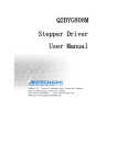
OPERATION AND
SERVICE MANUAL
HOLDING CABINET “N'ICE”
REV. 0 (03/2011)
Dear customer,
We wish to thank you for the trust you have shown us by choosing an IRINOX conservation unit, and we ask you to
carefully read the manual which will provide you with all the necessary information to immediately start optimal
conservation of your products.
We do in any case suggest that you study this manual so as to take advantage of all the potential and benefits that
your IRINOX conservation unit has to offer.
Proper operation of the machine also depends on its proper use.
Keep this manual near your conservation unit, so that it can easily be consulted by you and your operators.
Enjoy working with IRINOX!
Register online with Club Irinox : www.irinox.com
The graphic representation of the commands in this manual makes it easier to understand the operations to be performed, so that you can immediately start satisfactorily using your IRINOX conservation unit.
Legend of symbols
suggestions and details for proper use of the conservation unit
instructions for your safety
Additional information in this manual
Guarantee and service information
Validity of guarantee: for single parts, 12 months from invoice date, as shown in the current price lists.
Contacts:
Customer service:
Assistance for use
Technical service - spare parts
Fax
E-mail
Web site
+39.0438.5844
+39.0438.5844
+39.0438.2020
+39.0438.2023
[email protected]
www.irinox.com
For any request concerning your conservation unit, always specify:
• The model
• The serial number
which are shown on the label on the machine.
CONTENTS
1. GENERAL DOCUMENTATION
4
1.1 GENERAL WARNINGS
4
1.2 INTRODUCTION
4
1.3 TRANSPORT AND HANDLING
4
1.4 UNPACKING AND DISPOSAL OF PACKAGING
5
1.5 BASIC SAFETY INSTRUCTIONS
5
2. INSTALLATION
6
2.1 PLATE DATA
6
2.2 POSITIONING
6
2.3 DIMENSIONAL DATA
7
2.4 AMBIENT TEMPERATURE AND AIR CIRCULATION
8
2.5 COOLING POWERS
8
2.6 ELECTRICAL CONNECTION
8
2.7 REFRIGERATION CONNECTION
9
2.8 CONDENSATION DISCHARGE CONNECTION
10
2.9 CONNECTION OF WATER COOLED UNITS
10
2.10 NOTES FOR INSTALLER
11
2.11 SAFETY AND CONTROL SYSTEMS
11
2.12 R404a GAS SAFETY INFORMATION
12
2.13 DISPOSAL OF MACHINE
12
3. OPERATION
13
3.1 USE
13
3.2 CONTROL PANEL
13
3.3 DESCRIPTION AND OPERATION
14
3.4 SHUTDOWN MODES
17
3.5 SUGGESTIONS FOR USE
17
4. MAINTENANCE / SERVICE
18
4.1 ROUTINE MAINTENANCE
18
4.2 CELL CLEANING
18
4.3 CONDENSER CLEANING
19
4.4 FAULT SEARCH
19
4.5 SPECIAL MAINTENANCE
21
3
1. GENERAL DOCUMENTATION
1.1. GENERAL WARNINGS
• This does not include products that require constant
monitoring and recording of the temperature, such as:
- heat-sensitive chemical products
• - medicines
- blood products
The manufacturer shall not be held liable for any damage
arising from incorrect and unreasonable use, such as:
- improper use by untrained personnel.
- modifications or works which are not specific to the
model.
- use of spare parts which are not original or not specific
to the model.
- failure to comply with even a part of the instructions
in this manual.
• This manual is an integral part of the product. It
provides all information required for correct installation, proper use and maintenance of the machine.
• The user must read this manual and refer to it as
needed. It must be kept in a place that that all authorized workers (installer, user, maintenance technician).
• The conservation unit is intended for professional
use. Therefore, it is to be used only by skilled personnel.
• The conservation unit is intended only for its designed
use, i.e. the conservation of foodstuffs.
1.2 INTRODUCTION
Installation must be performed authorized and specialized personnel, respecting the instructions in this manual.
With each single machine, the manufacturer provides a
declaration of compliance with machinery directive
2006/42 and directive 2006/95.
Should the machine be supplied with a remote condenser
unit, it is the responsibility of the installer to check all
connections and to issue a declaration that the installation was duly performed and is in accordance with the
aforementioned directive.
1.3 TRANSPORT AND HANDLING
• All necessary precautions must be followed when
handling the chiller to prevent damage to it and the
instructions on the package must be respected.
• Loading and unloading of the machine on the means of
transport can be performed using a forklift or pallet truck
with forks that are more than half as long as the cabinet.
The hoisting apparatus must be suitably chosen on the
basis of the size and mass of the packaged machine as
indicated on the package label ( see Table 1).
Table 1
NET
CARDBOARD PACKAGING
WEIGHT
m3
kg
W (mm) H (mm) D (mm)
kg
CRATE PACKAGING
W (mm) H (mm)
D (mm)
m3
kg
Model of conservation units
NICE
165
760
2220
905
1,5
200
840
2270
830
1,6
250
500
650
0,2
40
760
500
760
0,3
50
Model of condensing units (if remote)
Condensing units
26
650
4
1.4. UNPACKING
• Remove the cardboard or wooden packaging or box
from the wooden base on which the machine is
standing,
lift the machine using suitable equipment (forklift),
remove the wooden base and stand the machine in
the chosen place ( see par. 2.2).
• Check the condition of the conservation unit after
having removed the packaging.
• Remove the protective PVC film from all sides (fig. 1).
•
Use protective gloves to handle the packing
and the wooden base.
• N.B.: all the various parts of the packaging must be
disposed of according to the rules of the various
Countries in which the chiller will be used. In any case,
none of the packaging must be left in the environment.
Fig. 1
1.5. BASIC SAFETY INSTRUCTIONS
•
•
•
•
•
If the instructions in this manual are not followed, the
user takes upon himself responsibility for any
operations carried out on the machine.
These are the safety rules in general:
do not touch the machine with damp hands or feet
do not work on the machine barefoot
do not insert screwdrivers, kitchen utensils or other
objects between the guards and moving parts
before cleaning or carrying out routine maintenance,
disconnect the machine from the mains by turning the
main switch off and removing the plug
do not pull at the cable to unplug the machine.
5
2. INSTALLATION
2.1. PLATE DATA
• Check that the data on the plate and the electric
power supply characteristics correspond (V, kW, Hz,
no. of phases and available power).
• The plate with the characteristics of the unit is found
on the right side of the conservation unit (fig.2) and
under the control panel.
31010
CORBANESE (TV)
ITALY
Model
Serial number
mm/yy/progres.
Mod.
y/n
Ph
V
Preparation of machinery rooms for the condensing
units must comply with fire prevention standards in the
country of installation. Contact the local fire department
for instructions.
Hz
Kw
A
Also keep in mind that the intervention of safety
valves or fuse plugs in the refrigerating circuit will result
in the immediate discharge in the environment of all the
coolant used. Please arrange for suitable disposal
methods and emergency measures as shown in the
coolant technical data sheet ( see par. 2.12).
Compressor
HERMETIC
Refrigerant
R404
Frequency
Charge
Power
Design pressure (Low)
KPa
Design pressure (High)
KPa
Class
Volume
Phase
Volt
Rated Load
IP
PED Code
Fig. 2
Climatic classes:
• 4 (environment temperature 30°C with relative humidity
55% not condensing) according to CEI EN 60335-1
regulations, CEI EN 60335-2-89, ISO 23953-2:2005(E).
2.2. POSITIONING
• The machine must be installed and tested by fully
respecting the accident-prevention standards, traditional precautions and the laws in force.
• The installer must check for any fire-prevention rules
(consult the local fire department for instructions).
• Place the machine in its location.
• Permanently level the appliance by means of the
adjustable feet. Use special hoisting apparatus for
the heaviest machines (fig. 3).
Fig. 3
• If the cells are not levelled, their proper functioning and
the drainage of condensation may be jeopardized.
Avoid (Fig.4):
• Places exposed to direct sunlight
• Closed locations that are hot and have poor air circulation ( see table 2).
• Avoid installing the machine near any source of heat.
Fig. 4
6
Power input
2.3. DIMENSIONAL DATA
730mm
B
1942mm
2056mm
E
B
56
1307.5
590mm
821mm
E
675mm
B-B
E-E
7
2.4. AMBIENT TEMPERATURE AND AIR CIRCULATION
For air cooled refrigeration units, the air temperature in
the place of operation must not exceed 30°C. Declared
performance cannot be guaranteed if this temperature
is exceeded.
The remote condensation units must be installed in
special rooms or outdoors, protected against direct
sunlight. If circumstances make it necessary, the installer
must decide whether to provide a covering or shelter.
Sufficient air circulation must however be ensured.
Table 2
MINIMUM AIR CIRCULATION
m3/h
AIR
638
Table 3
MAXIMUM WATER USE (when foreseen)
Well water
(l/h)
119
Values referred to the declared condensation power at -10/+40°C in
accordance with EN12900.
For greater details see table 2.
2.5. COOLING POWERS
Table 4
Cooling yield [W]
Condensation power [W]
1172
1863
Declared values at T.evap=-10°C and T.cond.=+40°C. Superheating in
accordance with EN12900.
2.6. ELECTRICAL CONNECTION
Up the line from each unit it is obligatory to install an
automatic circuit breaker in compliance with the laws
in force in the Country of installation.
The power supply is to be carried to the electrical panel
of each single unit, as per the data in Table 5.
• The electrical power cables must be properly sized
for the units installed;
• The electrical cables must be placed and fastened in
the cable passage, and laid suitably for the place of
installation;
• Each wire must be inserted to the corresponding
terminal.
• The earth wire must be correctly connected to an
efficient earthing system.
Fig. 7
Fig. 6
The manufacturer declines any responsibility
or guarantee obligations if damage occurs to the
unit, persons or things due to installation that is
incorrect and/or does not respect the laws in force.
Table 5
POWER SUPPLY
Voltage Frequency
nominal
POWER SUPPLY
defrosting
ABSORPTION
POWER SUPPLY
CABLE
REMOTE CONDENSING UNIT
CABLES (if foreseen)
Poles
Power
Current
Power
Current
(kW)
(A)
(kW)
(A)
50
1P+N+PE
0,96
5,5
1,9
8,9
FG7OR
3G1,5mm2 FG7OR 2x1,5mm2 + 3G2,5mm2
230
60
1P+N+PE
1,1
6,3
2
9,6
FG7OR
3G1,5mm2 FG7OR 2x1,5mm2 + 3G2,5mm2
200
50
2P+PE
0,94
5,7
1,8
9,8
FG7OR
3G1,5mm2 FG7OR 2x1,5mm2 + 3G2,5mm2
200
60
2P+PE
1,1
6,4
2
10,5
FG7OR
3G1,5mm2 FG7OR 2x1,5mm2 + 3G2,5mm2
(V)
(Hz)
230
NOTE: cable sized for a length of 7m with industrial voltage drop ∆V% ≤ 1%
8
Type
Section
Type
Section
2.7. REFRIGERATION CONNECTION
2.7.1. Installation at same level
General criteria that must be met for the installation of
remote units:
1) Slope of pipes (Fig.8)
2%
CO
MP
RE
2) Tightening of brackets on insulated pipes.
For the quantity of brackets to apply on the refrigeration connecting lines of the remote unit see table 6.
SS
OR
Fig. 8
3) Hermetic welding (Fig.10).
Table 6
4) Creation of vacuum (0.03mBar) in the connection
pipes (delivery and suction). Unless otherwise specified, the condensing unit is charged with freon.
DISTANCE
Cell -> Remote group
5) Check vacuum seal of pipes.
6) Opening of cut-off bibcocks on condensing unit.
7) Check for leaks.
NUMBER OF
BRACKETS
5 metres
2
10 metres
3
15 metres
5
20 metres
7
25 metres
8
8) Check of exact gas charge via the liquid flow indicator
located on the condensing unit.
9) Checking the condensation water circulation and
pressure (system with water condensation).
Fig.9
The criteria listed above are sufficient for installation at the same level (Fig.11)
Fig.10
Suction pipe
Fig.11
9
Installation
at same level
2.7.2. Installation at different levels
If the remote group is installed higher than the unit (fig.
13), it is necessary to fit a siphon at the beginning of each
departure or upward section (a), at intervals of 1.8 metres
of difference in level along the return pipe, and at every
arrival (b).
Installation at
different levels
If the remote unit is installed lower than the unit, siphons
are not necessary (fig. 12).
Suction pipe
Fig.12
Fig. 13
2.7.3. Refrigeration connection of remote groups
Diameters for appliance feed pipes are sized in accordance with the installation distance up to a maximum of
15 metres ( see table 7).
For greater distances please consult the manufacturer.
The insulation of suction and hot gas pipelines
must be carried out using good quality insulators of the
closed-cell type having a minimum thickness of 19 mm.
Table 7
Delivery line
Ø mm
Suction line
Ø mm
Hot gas line
Ø mm
8
10
8
Maximum pipe length: 15m
19 mm
2.8. CONDENSATION DISCHARGE CONNECTION
The conserver is supplied with a supplied condensate
water collection tray. A heater will provide for evaporation of the water contained in the tray.
2.9. CONNECTION OF WATER COOLED UNITS
• When testing (mains water), make sure the machine
is at a standstill, that the water supply is ready and
that water is not coming out of the condenser drain
pipe; in this case, adjust the pressure valve until
water coming out is completely stopped (Fig. 17).
• We suggest you install a gate valve and a viewable
filter on the water delivery pipeline. The condenser
water delivery and discharge pipes are indicated by
special nameplates. Both fittings are threaded 3/4”F.
• See Table 3 for maximum water consumption
CHARACTERISTICS OF THE LINE FOR
WATER COOLED UNIT
Maximum inlet pressure of water
1600 KPa
Minimum inlet pressure of water
50 KPa
Maximum inlet water temperature to
ensure normal operation of the unit
25°C (well water)
Fig. 17
10
2.10. NOTES FOR THE INSTALLER
Checking for correct installation and testing:
• Check for possible gas leaks on welded parts or
joints made during installation.
• Check for proper insulation of pipes connecting the
chiller with the remote condensing unit (when foreseen).
• Check electrical connection.
• Check power inputs.
• Check the standard pressures.
• Check water connection with the pressure valve adjustment during operation as well as proper water condensation circulation (when the condenser is at water).
• Run at least one complete conservation cycle (reach
the set temperature), and a manual defrost cycle.
Instruct the customer on the exact utilisation
of the chiller with specific reference to the use and
requirements of that specific customer.
Installation and commissioning must be
carried out by authorized personnel.
2.11. SAFETY AND CONTROL SYSTEMS
• Door microswitch (A): blocks operation of the fans in
the cell when the door is opened
• Protection fuses (B): protect the circuits against short
circuits and overloads.
• Fuse holders (C): contain the fuses and allow opening
and disconnection of circuits.
• Electronic cards (D): based on acquired parameters,
they control the various devices of the machine that
are connected to them.
• Control of temperature in cell and end of defrosting
(E): managed by the electronic card via probe NTC.
Fig. A
Fig. B
Fig. C
Fig. D
Fig. E
Fig. 19
11
2.12. R404A GAS SAFETY INFORMATION
Contact with the skin
If the product is nebulized or sprayed it can cause
cold burns to the eyes and skin. It does not seem to
be dangerous if absorbed by the skin. Repeated and
prolonged contact can cause loss of natural skin oils
with consequent drying, chapping and dermatitis.
• Identification of hazards
Exposure for long periods by inhalation can cause
anaesthetic effects. Very high levels of exposure may
cause anomalies in heartbeat and cause sudden death.
If the product is nebulized or sprayed it can cause cold
burns to the eyes and skin. It is dangerous for the
ozone layer.
• Ecological information
It breaks down quite quickly in the lower atmosphere
(troposphere). The products or decomposition have high
dispersion features and thus have a low concentration.
It does not promote photochemical smog (i.e. it is not
part of the volatile organic compounds -VOC- in compliance with the UNECE agreement).
Its ozone destruction potential (ODP) is 0.055 measured against a standard ODP of 1 for cfc11 (according
to the uNeP definitions).
This substance is regulated by the Protocol of Montreal
(1992 revision).
Product discharges into the atmosphere do not cause
long-term water contamination.
• First aid measures
Inhalation
Move the injured person away from the source of exposure to a warm place where he can rest. If necessary,
administer oxygen. Practice artificial respiration if the
person has stopped, or seems about to stop, breathing.
In the event of cardiac arrest perform CPR. Call for
medical assistance immediately.
Contact with the skin
Thaw the parts concerned using water.
Remove contaminated clothes.
Attention: in the event of cold burns, clothes can
adhere to the skin. In case of contact with the skin,
wash immediately and thoroughly with warm water. If
symptoms occur (irritation or blisters) ask for medical
assistance.
• Disposal suggestions
The best solution is to collect and recycle the product. If
this is not possible, it must be destroyed in a plant that is
authorised and equipped to absorb and neutralize the
acid gases and other toxic operating by-products.
Contact with the eyes
Wash immediately with an eye-wash or clean water,
keeping the eyelids apart for at least 10 minutes. Ask
for medical advice.
• Measures to be followed in the event of accidental
dispersion
Make sure that the person eliminating the dispersion is
suitably protected (using special apparatus to protect
the respiratory tract) while cleaning up spills.
If it is safe enough to do so, isolate the source of dispersion. If the dispersion is modest and ventilation is
sufficient, simply let it evaporate.
For dispersion of large quantities:
- ventilate the area;
- contain the spilled material using sand, soil or other
suitable absorbing material;
- prevent it from penetrating into drains, sewers, basements and construction excavations because the
vapours can cause suffocation.
Ingestion
Do not induce vomiting.
If the injured person is conscious, make him rinse his
mouth out and drink 200-300 ml of water.
Request medical assistance immediately.
Further medical care
Treatment for symptoms and support therapy where
indicated. Do not administer adrenalin or similar
substances after exposure because of the risk of
cardiac arrhythmia with the possibility of cardiac arrest.
• Fire-prevention measures
Non-flammable.
Thermal decomposition causes the emission of very
toxic and corrosive vapours (hydrogen chloride, hydrogen fluoride). In the event of fire, use breathing apparatus and suitable protective clothes.
• Handling
Avoid inhalation of high concentrations of vapours.
Concentrations in the atmosphere must be reduced to
a minimum and kept at the lowest reasonably possible
level, below the professional exposure limit.
The vapours are heavier than the air and for this
reason it is possible that high concentrations form near
ground level where ventilation is scarce. In these
cases, ensure adequate ventilation and wear protective
apparatus for the respiratory tract with a reserve supply
of air. Avoid contact with open flames and hot surfaces
because irritating and toxic products of decomposition
may form. Avoid contact of the liquid with eyes/skin.
Fire extinguishers
Use extinguishers suitable for the type of fire.
• Toxicological information
Inhalation
High concentrations in the atmosphere can cause an
anaesthetic effect and possible unconsciousness. Very
high levels of exposure may cause anomalies in heartbeat and cause sudden death.
Even higher concentrations can cause suffocation due
to reduced oxygen content in the air.
2.13. DISPOSAL OF THE MACHINE
Demolition and disposal of the machine must be carried
out in accordance with standards currently in effect in
the country of installation, especially concerning the
refrigeration gas and lubrication oil of the compressor.
12
3. OPERATION
3.1. USE
The N'ICE conserver was designed for conservation of
food products.
N’ICE can work at +15 / -25°C.
Especially:
• POSITIVE mode (3°C), suitable for the conservation
of fresh products, or for brief periods, of cooked food;
• NEGATIVE Mode (-20°C), suitable for the conservation of frozen products also for long periods of time;
• CHOCOLATE Mode (14°C), suitable for the conservation of chocolate based products (for example pralines).
3.2. CONTROL PANEL
P1
P2
P5
P6
Fig. 20
P4
P1: Light/humidity key
P2: Manual defrost key
P3: ON/Stand By Key
P4: Value decrease key
P5: Programming Key
P6: Value increase key
13
P3
DATE AND TIME ADJUSTMENT
Phase
Description
1
Press key P4
2
Through keys P4
3
Press key P5
The indicator
4
Select the current year by pressing key P4
5
Press key P5
for 1 second
or P6,
select "rtc" on the display
to confirm and access the clock setting menu.
will flash
or P6
(last 2 digits, i.e. 2011 = 11)
to confirm and move on to the following setting.
- YEAR (display: “YY 01”)
- MONTH (display: “nn 01”)
- DAY (display: “dd 01”)
- TIME (display: “hh 01”) in 24 hour format
- MINUTES (display: “nn 01”)
6
After setting the minutes, press key P5
"rtc" will appear on the display.
The indicator
7
Press key P3
to confirm and save the clock setting.
goes off.
to exit the menu.
3.3. DESCRIPTION AND FUNCTIONING
Conservation cycle
Phase
Description
1
With the conservation system in stand-by, select the operation mode.
See paragraph common functions. ☞ Operation mode selection.
2
Press key P3
for 2 seconds to start up conserving.
– The display will show the detected chamber temperature
3
Change set temperature:
Press key P5
:
– The indicator flashes
– The display shows the set time
Through keys P4
and P6
change the setpoint
– Do not press any key for 15 seconds or press key P5
to exit and save changes.
– The indicator
stops flashing
– The display will show the detected chamber temperature
4
End conserving
Press the key P3
for 2 seconds
– The display switches off ☞ Conservation system in stand-by.
– The indicator
is turned on
14
Common functions
Function
Functioning mode
selection.
Description
Put the conserver in Stand-by by pressing key P3
.
Press key P5
for 4 seconds.
The display shows the set functioning mode.
Through keys P4
and P6
set the desired functioning mode, where:
POS = POSITIVE mode
NEG = NEGATIVE mode
CIOC = CHOCOLATE mode
Press key P5
to confirm the data entered and exit the menu.
If no key is pressed, after a pre-set time,
one automatically exits the menu and the entered data is saved.
Humidity check
(for POSITIVE or
CHOCOLATE
mode)
Press the key P1
for 4 seconds.
Through keys P4
and P6
set the relative humidity level desired, where:
Ur1= low humidity
Ur2= average humidity
Ur3= high humidity
Press key P1
to confirm the data entered and exit the menu.
If no key is pressed, after a pre-set time, one automatically exits the menu
and the entered data is saved.
Overcooling
Press key P6
for 4 seconds to start up the Overcooling cycle.
Manual defrost
Press key P2
for 4 seconds to start up a defrost cycle.
Switching on
of cell light
Upon door opening, the light inside the cell is automatically switched on.
Key locking
With the light off, press key P1
to switch on the light inside the cell.
With the light on, press key P1
to switch off the light inside the cell.
To block the functioning of the keys:
Press keys P3
+P4
simultaneously for 1 second
The display shows "Loc" for 1 second.
To unlock the functioning of the keys:
Press keys P3
+P4
simultaneously for 1 second
The display shows "UnL" for 1 second. .
15
Signals
Meaning
Indicator
Steady
Flashing
Change temperature set point
Compressor run requested but
pending safety time end
Compressor command
Defrosting in progress
Defrosting in progress but pending
compressor safety time end
Evaporating fan command
During evaporating fan stop time
Internal cell light manually
switched on through pressing of key P1
Internal cell light switched on for door opening
Liquid line electrovalve command
NOT USED
NOT USED
Date and time change in progress
All the information regarding HACCP
alarms have been viewed
At least one new HACCP alarm was recorded
NOT USED
NOT USED
NOT USED
NOT USED
OverCooling cycle in progress
NOT USED
Alarm or error is in progress
NOT USED
The temperature measure unit is °C
NOT USED
The temperature measure unit is °F
NOT USED
The instrument is in standby
NOT USED
Indications
Meaning
Display
Key lock activated
Running set point locked
Function required not available
16
3.4. SHUTDOWN MODES
In case of emergency, to switch off the conserver, press
key P3
Fig. 20
for 2 seconds and disconnect power supply.
ATTENTION!
By pressing key P3
with machine running, the
conserver is placed in Stand-by: all the commands are
removed from the various components; the conserver
IS NOT DISCONNECTED FROM POWER SUPPLY.
Fig. 21
3.5. SUGGESTIONS FOR USE
Before putting the machine in operation, it is necessary
to carefully clean the inside of the cell ( see par. 4.2)
3.5.1. Pre-cooling
Before using the conservation unit for the first time, or
after a long period of disuse, pre-cool the cell by running
the machine empty until the set working temperature is
reached.
To obtain good performance from the machine
without altering foods, we suggest the following:
• do not place hot foods or liquids in the cell without a
cover.
• arrange products so as to favour cold air circulation
throughout the cell.
• avoid prolonged and frequent door opening.
OK!
3.5.2. Loading the machine
Take care that there is enough space between pans,
so as to allow sufficient air circulation.
If the machine is not fully loaded, spread the pans
and the load evenly throughout the entire height, avoiding
concentrations.
When using the N'ICE in positive mode (20÷0°C),
run the conservation unit empty for at least four hours so
as to work at the desired relative humidity.
Fig. 22
17
NO!
4. MAINTENANCE
4.1. ORDINARY MAINTENANCE
The information and instructions contained in this chapter
are intended for all personnel who work with the machine:
t h e u s e r, t h e m a i n t e n a n c e t e c h n i c i a n , a n d a l s o
non-specialised personnel.
Basic safety guidelines
To perform cleaning and maintenance in complete safety,
please refer to the standards of safety in par. 1.5 (Fig.23):
• do not touch or work with the machine with damp hands
or feet
• do not insert screwdrivers, kitchen utensils or other
objects between the guards and moving parts
• before cleaning or carrying out routine maintenance,
disconnect the machine from the mains by turning the
main switch off and removing the plug
• do not pull on the power cord to disconnect the machine
from the power supply
It is strictly forbidden to remove guards and safety
devices to effect routine maintenance operations. The
manufacturer declines any responsibility for accidents
caused by not observing the instructions above.
Before putting the machine in operation, it is necessary to carefully clean the inside of the cell as indicated in
paragraph 4.2.
Fig. 23
4.2. CELL CLEANING
To ensure hygiene and to protect the quality of the foods,
the inside of the cell must be cleaned frequently, based on
the types of conserved foods.
We recommend weekly cleaning.
The shape of the cell and of the interior components
make it possible to clean it using a cloth or sponge.
Use water and neutral, non-abrasive detergents.
The cell can be rinsed using a cloth or sponge dipped in
water or a moderate jet of water (having a pressure that
does not exceed the pressure of the system).
Fig. 24
Do not scrape the surface using sharp or abrasive objects.
Do not use abrasive products, solvents or thinners.
When cleaning, always wear protective gloves.
18
4.3. CLEANING THE CONDENSER
In order for the conservation unit to work correctly and
efficiently, the air condenser must be kept clean to allow
free airflow. This operation should be done at least
every 30 days. This can be done by using a non-metal
brush to remove all the dust and lint from the condenser
fins. We suggest you use a vacuum cleaner to prevent
the dust from going into the environment. If there are
any greasy deposits, use a brush soaked in alcohol.
Do not scrape the surface using sharp or abrasive
objects.
Always use protective gloves, glasses and masks
to protect the respiratory tract during cleaning.
Fig. 25
4.4. FAULT SEARCH
The machines' electronic control is supplied with a sound
and visual signal system which signals the presence of
an alarm; press a key to silence the sound alarm.
Diagnostics managed by the electronics:
Meaning
Display
Minimal temperature (HACCP alarm)
Maximum temperature (HACCP alarm)
Open door (HACCP alarm)
No voltage (HACCP alarm)
Defrosting ended due to maximum duration
Faulty chamber probe
Faulty evaporator probe
Clock error
19
Diagnostics NOT managed by the electronics:
MALFUNCTION
POSSIBLE CAUSE
POSSIBLE SOLUTION
No power supply
Check the connection to the electrical line
Intervention of protection fuses
Replacement of fuses by an authorized
technician
No power supply
Check the connection to the electrical line
Faulty fan
Technician required to replace fan
Faulty card
Technician required to replace card
No power supply
Check the connection to the electrical line
The front card of the cell
does not turn on
The cell fans do not run
The compressor does not work
The compressor runs but
does not cool the cell
The condenser fan does
not work
Intervention of internal clixon due to overload Intervention by a technician
No consent from electronic card
Technician required to replace
electronic card
No refrigerant gas
Intervention by a technician
Solenoid valve faulty
Intervention by a technician
Condenser dirty
Clean condensing coil
Liquid line solenoid valve faulty
Technician required to replace solenoid
valve or bobbin
Defrost line solenoid valve faulty
Technician required to replace solenoid
valve or bobbin
No power supply
Check the connection to the electrical line
Fan faulty
Technician required to replace fan
No electronic board consent
Intervention of a technician to replace
the electronic card
Incorrect programming of defrost cycles
Check programming of defrost cycles
Solenoid valve or bobbin of defrost line faulty
Technician required to replace solenoid
valve or bobbin
No evaporator defrost
20
4.5. SPECIAL MAINTENANCE
The information and instructions contained in this paragraph are for the exclusive use of specialized personnel
who are authorized to intervene on the electronic and
refrigeration components of the machine.
Fig. 28
4.5.1. How to access the electronic cards and
the electrical panels.
The electronic cards and the electrical control boards
are located in the top part of the machine, protected by
a plate. Remove the electric power supply before intervening for maintenance. Then remove the steel cover,
unscrewing the locking screws.
At the end of maintenance operations, accurately reassemble the covers and lock the locking screws.
Fig. 29
21
Cod. 443153 - n. rev. 0 - 03/2011 - Printed in Italy
S.p.A.
Via Madonna di Loreto, 6/B
31010 CORBANESE di TARZO (TV) Italy
Tel. +39.0438.5844 r.a. - Fax +39.0438.5843
www.irinox.com
[email protected]
Irinox in the world:
IRINOX D/A/CH/Lux
Mobil: +49 (0) 172 759 77 91
T. +39 0438 584 222
F. +39 0438 584 120
[email protected]
www.irinox.com
IRINOX USA
31 Eastman Street
South Easton | MA 02375
T. +1 508 230-5818
F. +1 508 230-5819
[email protected]
www.irinoxusa.com
For more information visit
www.irinox.com