1
VSCADA User Manual Page 1 VSCADA Vehicle Supervisory Control and Data Acquisition User Manual Lafayette College Lafayette Formula Electric Vehicle Electrical and Computer Engineering ECE 492 Spring 2015 Group Members Adam Cornwell Bikram Shrestha John Gehrig Rameel Sethi Sam Cesario Yiming Chen LAFAYETTE COLLEGE
ELECTRICAL AND COMPUTER ENGINEERING
VSCADA User Manual Page 2 Using This Manual This manual is intended to familiarize the average user with the VSCADA system, and demonstrate the proper operating procedures. The information covered includes System Design and Capabilities, a brief overview of the structure of the system, subsystems and the responsibilities of each part of the system. Operating procedures reviews basic tasks, such as turning on the system on, getting the car into drive mode, and common driver and mechanic interactions with the software. Basic Maintenance and Troubleshooting sections cover how to diagnose and fix common system errors. This document concludes with a “Frequently Asked Questions”. Getting Started If this is the first time the system is being used and it needs to be set up, please refer to the maintenance manual for instructions. Listed below are the manual sections and why you would want to read them. 1. System Design and Layout An overview of the system design and how it works 2. User Interface Pictures of the System screens and descriptions of their functionalities 3. Operational Procedures A primer covering the procedures needed to operate basic functions of the system 4. Troubleshooting Common problems which may occur and troubleshooting steps to help solve them 5. Frequently Asked Questions Common questions about the VSCADA system and their answers LAFAYETTE COLLEGE
ELECTRICAL AND COMPUTER ENGINEERING
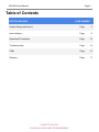
VSCADA User Manual Page 3 Table of Contents SECTION HEADING PAGE NUMBER System Design and Layout Page 4 User Interface Page 8 Operational Procedures Page 12 Troubleshooting Page 14 FAQs Page 16 Glossary Page 17 LAFAYETTE COLLEGE
ELECTRICAL AND COMPUTER ENGINEERING
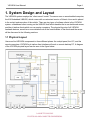
VSCADA User Manual Page 4 1. System Design and Layout The VSCADA system employs the “clientserver” model. The server runs on an embedded computer, the VIA Embedded VAB820, which comes with a customized version of Ubuntu Linux and is placed in the cockpit enclosure box of the vehicle. There are two types of software clients in the VSCADA system: a dashboard client running on the VAB820 itself which handles the incar dashboard screen, and the pit station clients which run on remote computers. The physical layouts of all VSCADA hardware devices, as well as a more detailed look at the functionalities of the clients and the server will be discussed in the following sections. 1.1 Physical Layout Users can find VSCADA components in three different places: the cockpit panel, the VCI, and the remote computers. VSCADA’s pit station client interface will work on remote desktop PC. A diagram of the VSCADA physical layout can be seen in the figure below. LAFAYETTE COLLEGE
ELECTRICAL AND COMPUTER ENGINEERING
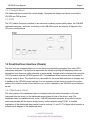
VSCADA User Manual Page 5 1.1.1 Cockpit Panel The dashboard client controls the cockpit display. Alongside the display are buttons connected to VSCADA via CAN protocol. 1.1.2 VCI The VCI (Vehicle Computer Interface) is an enclosure containing system safety relays, the VAB820 embedded computer, and ports connecting to the VAB820’s inputs and outputs. A diagram of the VCI ports is shown below. 1.2 Front End User Interface (Clients) The front end user interfaces which run on the clients are physically segregated from other LFEV subsystems and parts. The clients are responsible for actively acquiring and displaying certain car information from the server, either manually or automatically, through wired or wireless links using the TCP/IP protocols and the VSCADA server’s API. The dashboard client is active when the vehicle is driving or readytodrive. The clients are not responsible for the actual data collection or storage; that is handled in the VSCADA server backend. It is not necessary for the clients to monitor the system states of the vehicle in order for the vehicle to run, as this is handled in the VSCADA server backend as well. 1.2.1 Dashboard Client The sole purpose of the dashboard client is to display limited but useful information to the user (assumed to be the driver) on the dashboard screen placed in front of the driver’s seat. The dashboard client is installed and runs on the VAB820 embedded computer along with the server, and communicates with the server directly (wired) on the hardware using TCP/IP. A detailed explanation of the dashboard client can be found in sections 3.1 and 3.2. The figure below contains a software block diagram of the dashboard client. LAFAYETTE COLLEGE
ELECTRICAL AND COMPUTER ENGINEERING
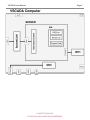
VSCADA User Manual Page 6 1.2.2 Pit Station Client The major functionalities of the pit station clients are: 1. Accessing all data from the server 2. Observing all conditions of the vehicle and its subsystems 3. Adjusting system parameters wirelessly without needing any direct contact with the VSCADA hardware 4. Viewing and testing the operation of the VSCADA system A detailed explanation of the pit station clients can be found in section 3.3. 1.3 VSCADA Back End (Server) The VSCADA back end (server) communicates directly with other LFEV subsystems through a CAN bus. The hardware attached to the CAN bus includes the motor controller, the GLV sensors, the “pacman” computers (TSV’s pack managers) and the cockpit panel buttons. The server starts up and logs in automatically when the VSCADA system turns on; it then constantly listens to the CAN bus to log data and store it in a database. The server is responsible for keeping the entire LFEV system in a sane and stable state; it has the ability to cut off power to the system if fatal errors occur. The server remains passive while communicating with all clients. This means that the server sends out data only when a client requests the server to do so; if no client request is received by the server, none of the data collected will become available to the clients and therefore the users. The figure below contains a software block diagram of the server. LAFAYETTE COLLEGE
ELECTRICAL AND COMPUTER ENGINEERING
VSCADA User Manual Page 7 LAFAYETTE COLLEGE
ELECTRICAL AND COMPUTER ENGINEERING
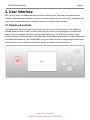
VSCADA User Manual Page 8 2. User Interface Both types of client, the dashboard client and the pit station client, have their own graphical user interface. The dashboard interface uses buttons on the cockpit panel for user inputs. A keyboard and mouse are recommended as the standard user inputs to the pit station interface. 2.1 Dashboard Controls The dashboard controls are used to select options in any menu or dialog boxes on the display, to indicate when the driver is ready to drive, and to stop the vehicle in an emergency or for any other reason. The four navigational buttons used are selfexplanatory. The RTD button which is used stands for Ready to Drive and acts as the secondary confirmation that the driver is ready to drive after the vehicle has started up. The Cockpit BRB, or big red button, acts as an emergency stop and motor shutdown button. All of these buttons and the display are shown in the figure below. LAFAYETTE COLLEGE
ELECTRICAL AND COMPUTER ENGINEERING
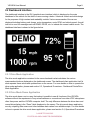
VSCADA User Manual Page 9 2.2 Dashboard Interface The dashboard interface is the GUI (graphical user interface) which is displayed on the main dashboard of the vehicle for the driver or users running a demo. It features a black and white design for the purposes of high contrast and readability outside. Various measurands of the car are displayed including battery pack charge, motor temperature, motor RPM, and vehicle speed. A small text box is used for messages such as DEMO, DRIVE, etc. to indicate the current vehicle mode. The dashboard interface is shown in the figure below. 2.2.1 Drive Mode Application The drive mode application contained in the server backend is what calculates the various measurands which are displayed on the dashboard screen. The dashboard client application itself is what requests those values and updates them on the screen. For more details on how to operate the drive mode application, please read section 3.3, Operational Procedures Dashboard Clients/Drive Mode Application. 2.2.2 Drive Mode Demo Application The drive mode demo runs in a way that makes it possible to see all functions of the VSCADA software without the requirement of any actual hardware or connections from other LFEV subsystems other than power and the VSCADA computer itself. The only difference between the drive demo and normal drive display is the “Demo” label displayed on the screen. The drive mode demo application runs by outputting fake sensor and other hardware data values from editable scripts. For more details on how to operate the drive mode demo application, please read section 3.4, Operational Procedures LAFAYETTE COLLEGE
ELECTRICAL AND COMPUTER ENGINEERING
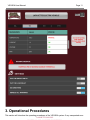
VSCADA User Manual Page 10 Drive Mode Demo Application. 2.3 Pit Station / Desktop Interface (Windows/Mac/Linux) The pit station interfaces contain two separate applications: the drive mode demo application and the maintenance mode application. 2.3.1 Drive Mode Demo Application The drive mode demo on the desktop interface looks the same and has the same functionality as the drive demo application which runs on the vehicle dashboard. Please see section 2.2.2 for a complete description and section 3.4, Operational Procedures Drive Mode Demo Application for operational instructions. 2.3.2 Maintenance Mode Application The maintenance mode application is designed so that it is possible to view and change all settings of the VSCADA software without login to the embedded system. The figure shown on the next page illustrates one screen in the application. The maintenance mode application can view the states of operation of the sensors, the motor controller and the TSV system, while controlling the physical relays connected to the VSCADA system. The maintenance mode application can also be used for calibration of the sensors, testing, debugging, reconfiguring of the system and analyzing data. Finally, the maintenance mode application can be run at the same time as the drive mode or drive mode demo application is running on either the vehicle itself or a pit station; this allows for everything to be inspected as the vehicle is being operated. For more details on how to operate the maintenance mode application, please read section 3.5, Operational Procedures Maintenance Mode Application. LAFAYETTE COLLEGE
ELECTRICAL AND COMPUTER ENGINEERING
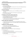
VSCADA User Manual Page 11 3. Operational Procedures This section will introduce the operating procedures of the VSCADA system. If any unexpected error LAFAYETTE COLLEGE
VSCADA User Manual Page 12 occurs during normal operation of the vehicle, please read section 5, Troubleshooting. 3.1 System Startup 1. Check the GLV batteries 2. Turn on the GLV master switch 3. Wait until the dashboard displays the startup screen; the server and the dashboard clients are now in their operating states 4. The VSCADA system should monitor other systems during startup of the car 3.2 System Shutdown 1. If the system goes into a critical state, press one of the BRBs (big red buttons) to open the safety relay. 2. Wait until the car stops moving and all other subsystems are operating safely 3. Turn off the GLV master switch 3.3 Dashboard Clients/Drive Mode Application 1.
2.
3.
4.
Turn the system on per the instructions listed in section 4.1 Wait for the VSCADA system to check other subsystems Push the RTD (Ready to Drive) Button VSCADA should now be showing the drive mode display to the driver on the dashboard screen; measurand values should change and not remain static 3.4 Drive Mode Demo Application 1. Follow all instructions in section 3.3; this can be run from a pit station computer or the car 2. In addition to the results from section 3.3, the message “DEMO” should be clearly displayed on the screen being used. 3.5 Maintenance Mode Application 1. Turn the system on per instructions listed in section 4.1 2. On the remote pit station client start the Maintenance application 3.6 File Transfer and Editing VSCADA system file transfers and editing can be done in the following ways. 3.6.1 Debugging Port 1.
2.
3.
4.
Insert an ethernet cable into the debug port. Connect the other end of the ethernet cable to a remote PC with ssh installed. From the remote PC, open the terminal application. Type the command: ssh user@{vscada server ip address} LAFAYETTE COLLEGE
VSCADA User Manual Page 13 to remotely login to the embedded computer. 5. Files in the embedded computer then can be edited, copied and transferred using commands in the terminal. 3.6.2 SD Card/Flash Drive A copy of all system logs is stored on a removable drive, either an SD card or a flash drive. Remove the device from the car and insert it into a remote PC to access and copy system logs. LAFAYETTE COLLEGE
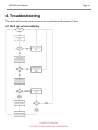
VSCADA User Manual Page 14 4. Troubleshooting This section will introduce some common errors or problems and the steps to fix them. 4.1 Start up error/no display LAFAYETTE COLLEGE
ELECTRICAL AND COMPUTER ENGINEERING
VSCADA User Manual Page 15 4.2 No Connection to the Server Check to ensure that your computer wireless is working. 4.3 System Installation Delete all of the installation files, redownload the installer and restart the installation. 4.4 System Startup Terminate the program and relaunch the system, if need be delete the program and reinstall. 4.5 System Software Updates Check the Lafayette Electric Vehicle website for the most up to date software if there is any. LAFAYETTE COLLEGE
ELECTRICAL AND COMPUTER ENGINEERING
VSCADA User Manual Page 16 5. Frequently Asked Questions The following questions and answers should help while using the VSCADA software. What is VSCADA? VSCADA stands for “Vehicle Supervisory Control and Data Acquisition”. VSCADA acts as the brain of the overall vehicle system. It provides comprehensive control and monitoring of the subsystems in the LFEV. VSCADA implements a “serverclient” model. For more information on the system design, please refer to section 2, System Design and Layout section. How do I start a system or program? Once the GLV battery powers the VSCADA computer hardware and the GLV master switch is on, both the VSCADA backend server and the dashboard client will start up automatically (section 4.1, operational procedures, system startup). A Pit station client can connect to the VSCADA server by running either the driver mode demo application or the maintenance application. How do I stop or power down a system or program? The VSCADA server program and the dashboard client on the car will shut down when GLV is powered off (section 4.2, operational procedures, system shutdown). Other VSCADA programs running on the pit station can be closed in the same manner as a typical computer program. Why is the dashboard not displaying/updating correctly? Referred to section 5.1, Troubleshooting. LAFAYETTE COLLEGE
ELECTRICAL AND COMPUTER ENGINEERING
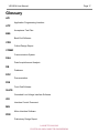
VSCADA User Manual Page 17 Glossary API Application Programming Interface ATP Acceptance Test Plan BES Back End Software CDR Critical Design Report COMM Communication System DAA Data Acquisition and Analysis DB Database DOC Documentation FES Front End Software GLVIS Grounded Low Voltage Interface Software ICD Interface Control Document MIS Motor Interface Software PDR Preliminary Design Report LAFAYETTE COLLEGE
ELECTRICAL AND COMPUTER ENGINEERING
VSCADA User Manual Page 18 SDK Software Development Kit SOC State of Charge TSVIS
Tractive System Voltage Interface Software UI User Interface VSCADA Vehicle Supervisory Control and Data Acquisition LAFAYETTE COLLEGE
ELECTRICAL AND COMPUTER ENGINEERING