1
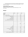
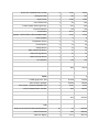
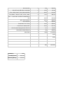
Status Letter Week 5 2/22/15 LFEV Team Milestones: VSCADA: Last week: System block diagrams and the GUI designs are drawn and included in the user manual. Able to run python code automatically after the system startup. This week: We are going to deliver the user manual. We will set up the logging daemon on the virtualbox. Install Linux on the embedded system once it arrives. Place the order for dashboard and microcontrollers. DYNO: Last Week: User manual completed and submitted to the website. Temperature sensor for motor selected and ready to order. Dyno software loaded onto computer. Dyno software works with Dyno sensors. This Week: Computer controllable throttle input to motor controller for safe and accurate out of room testing. Motor controller programmed using the Curtis software. TSV: Last week, we completed the schematic for implementing CAN on the BoB. We also completed schematics for a full system reset and the 24V pack indicator, though due to technical difficulties they are not all integrated into the same DxDesigner file. Additionally, we produced a pack wiring diagram for the TSV packs which was conspicuously missing from last year. For next week, we plan to begin working on the CDR, write the maintainability plan and fix the AMS board schematics. Also we will put out orders for the AMS boards, the new LCD displays and the computers we will be using. GLV: Last week we sketched out all panel interfaces except the Cockpit Panel. We also sketched out the internal layout/circuit diagram sketch of the VCI, TSI, and Side Panel. These sketches were added to our working User Manual. In the upcoming week, the GLV team plans on purchasing components for the GLV Power and VCI subsystems as well as the connectors for system integration. A new user manual will be submitted. Outstanding Action items: Website: Ken has started the process for getting us hosted long term. Steve Morton Papers Budget: Item/Group Quantity Price SCADA Embedden Computer System Total 1 400 400 Dashboard LCD display and controller 1 100 100 Wireless Radio 1 50 50 GPS radio 1 50 50 DCDC converter 1 35 35 Safety Loop Solid State Relay 2 10 20 Slave Sensor Micro Controller Hardware 4 15 60 GLV 0 24V battery 1 185 185 Smart Charger 1 25 25 overvoltage protector LTC4365 1 2 2 PolySwitch LVR055 1 2 2 Container 1 150 150 Board 1 40 40 Red LED McMasterCarr 2779K7 2 9.62 19.24 total 715 Green LED McMasterCarr 2779K2 2 14.52 29.04 Wiring and fuses 1 150 150 Acrylic Frame 1 16.68 16.68 Veam Powerlocks 4 55 220 Tractive System Active Light Lamp 1 44.6 44.6 Physical Container 1 150 150 Circuit Board 1 40.79 40.79 Speaker BUZZ PIEZO CIRC 42.85MM PANEL 1 37.55 37.55 Audio Amplifier 1 8 8 Temperature Sensor 4 6 24 Current Sensor 2 15 30 Voltage Sensor 2 19 38 Rate of Discharge Sesnor 1 15 15 Rate of Charge Sensor 1 15 15 State of Charge Sensor 1 6 6 VCI Container 1 150 150 DYNO 0 0 AWG (gage) wire 50ft 1 $75.00 $75.00 Wire connector package 1 $50.00 $50.00 Temp sensor LM20CIM7/NOPBCTND 3 $1.00 $3.00 4 to 8 pin adapter Motor controller 1 $20 $20.00 TSV Advanced Circuits PCD AMS and BOB boards 32 16 $512.00 parts from Mouser 1 459 $459.00 parts from digikey 1 141.7 $141.70 total total 1397.9 $148.00 Microcontroller 3 308 $924.00 Micro SD card 4GB Class 10 industrial 3 10.54 $31.62 Fuse 200A, Class T, A3A, 300Vac/160VDC 4 28.34 $113.36 Fuse Holder 200A AC, 300V, a Pole, molder 4 71.81 $287.24 Fans 119x25 24DC 100CFM 5W 2900RPM 43 dbA 4 40.95 $163.80 AIR 350A contractor 7 94.35 $660.45 50A miniTactor 7 40 $280.00 Panel Drain, Line 3, Grey 4 51.26 $205.04 Panel Source, Neutral, Blue 4 54.33 $217.32 LCD Character Display Module STN Y/G 4 11.5 $46.00 Galvanically Isolated Ethernet 4 102 $408.00 Other Parts 1 1600 $1,600.00 $0.00 $0.00 Total Money 5000 Total Requested 8310.43 Remaining Money 3310.43 total $6,049.53 2/22/2015 Search Completed pack wiring diagram Asana Tasks due within the last 7 days Printed from Asana Adam Cornwell Adam Cornwell: Finalize system states and define inputs/outputs due Feb 18 Alex Hytha Alex Hytha: Temp Sensor chosen and ordered due Feb 21 Alex Hytha: TSV Safety Plan due Feb 19 TSV safety plan must be written Removing AMS PCBs Removing Batteries Reset AMS PCBs Reset Pacman AIR bypass voltage/current probing High power plugs Aloysius Posillico Aloysius Posillico: TSI Panel Sketches AP due Feb 21 Aloysius Posillico: TSI Circuit Sketches AP due Feb 21 Bikram Shrestha Bikram Shrestha: Design GUI for 3 modes due Feb 20 Brendan Malone Brendan Malone: User manual due Feb 19 Daniel Zakzewski Daniel Zakzewski: Side Panel BOM DZ due Feb 21 Daniel Zakzewski: VCI Circuit Sketches DZ due Feb 21 Daniel Zakzewski: Side Panel Internal Layout Sketch DZ due Feb 21 Daniel Zakzewski: Side Panel Circuit Sketches DZ due Feb 21 Hansen Liang Hansen Liang: Choose new LCD display, interface https://app.asana.com/0/search/27543017738627/27282623335957 due Feb 22 1/3 2/22/2015 Search Completed pack wiring diagram Asana Jaejoon Yang Jaejoon Yang: Proposal for 20V indicator design due Feb 22 John Bloore John Bloore: Dyno to computer integration with sensors due Feb 21 John Gehrig John Gehrig: Place the purchase for embedded system due Feb 23 John Gehrig: Finalize schedule with faculties due Feb 22 Jordan Blake Jordan Blake: Completed pack wiring diagram due Feb 22 Jordan Frank Jordan Frank: TSI Safety loop circuit sketch JF due Feb 21 Kai Ottaway Kai Ottaway: Rearrange top of box due Feb 19 Katie Nellis Katie Nellis: Proposal for full system reset designs due Feb 22 Nate Hand Nate Hand: Motor Controller Cooling system built due Feb 21 Nick DiNino Nick DiNino: GLV Battery Circuit Sketches ND due Feb 21 Significant redesign of the circuit used as a power monitor has pushed back sketching of the circuit. Nick DiNino: GLV Battery Panel Sketches ND due Feb 21 Rameel Sethi Rameel Sethi: Simple startup software on Virtualbox due Feb 20 Sam Sam : Software level CAN outline and library design due Feb 20 Stephen Mazich Stephen Mazich: User Manual https://app.asana.com/0/search/27543017738627/27282623335957 due Feb 19 2/3 2/22/2015 Search Completed pack wiring diagram Asana William Stathis William Stathis : Schematic implementation for CAN bus due Feb 22 Yiming Chen Yiming Chen: Complete User Manual due Feb 20 Zach Helwig Zach Helwig: VCI Panel Sketches ZH due Feb 21 Zach Helwig: GLV Hub Panel Sketches ZH due Feb 21 Zach Helwig: Side Panel Panel Sketches ZH due Feb 21 Unassigned User Manual Update due Feb 21 ATP submission 2 due Feb 21 D011 Calibration and Accuracy due Feb 23 Any data acquisition system design or test plan must be accompanied by a Calibration and Error Analysis document that estimates the uncertainties associated with all system measurands. This document must include both analytical estimates of measurement uncertainty, as well as a justified design of acceptance tests to determine the uncertainty achieved in practice. The testing design from this document shall be incorporated into the system ATP. D004 Acceptance Test Plan due Feb 23 The Acceptance Test Plan (ATP) is a document that describes how the system as a whole will be tested and demonstrated so as to prove compliance with all requirements and specifications. The ATP should include forms that can be filled out by testers during execution. These filled out forms will be used to create the ATR. Compliance must be conclusively proved in any of the following three ways: • Analysis – detailed logical analysis can demonstrate compliance by reasoning from known facts (a priori or empirically) similar to the form of a mathematical proof. Analysis can be used cited research results in conjunction with the documented results of subsystem QA testing, along with generally accepted technical principles to prove system level requirements are met. Analysis memos and relevant data are attached to the ATR. • Test – an explicit test, experiment, or demonstration can be used to prove compliance with a certain requirement by acquiring new empirical facts and combining these with analysis as described above. The comprehensive results of any measurements conducted as part of an ATP test is included in the ATR, along with date and time of the test, the pass/fail criteria, uncertainty, statistical confidence, pass/fail result, witness name, and witness signature.. • Inspection –compliance is made evident by directly examining the system. Photographs with detailed annotations or other evidence gathered in an inspection is included in the ATR. The ATP should be arranged to minimize the work involved in testing. If possible, multiple requirements should be demonstrated by each test. The ATP should include a compliance matrix making it obvious that all requirements have been addressed by the plan. Numerical specifications shall be considered “passed” if the measured value is demonstrated by empirical statistical trials to meet the specification at a 90% confidence interval. https://app.asana.com/0/search/27543017738627/27282623335957 3/3 2/22/2015 Search Asana Incomplete Tasks due within the next 7 days Printed from Asana Adam Cornwell Adam Cornwell: PACMAN Communication Library due Feb 27 Alex Hytha Alex Hytha: Complete and submit ATP Final draft due Feb 28 Aloysius Posillico Aloysius Posillico: TSAL Circuit Schematic AP due Feb 28 Aloysius Posillico: TSAL Approval and Submission AP due Feb 28 Aloysius Posillico: TSAL Component Purchase AP due Feb 28 Brendan Malone Brendan Malone: Model the motor in software due Feb 28 Daniel Zakzewski Daniel Zakzewski: Cockpit Panel BOM DZ due Feb 28 Daniel Zakzewski: Cockpit Panel Panel Sketches DZ due Feb 28 Daniel Zakzewski: Cockpit Panel Internal Layout sketch DZ due Feb 28 Daniel Zakzewski: VCI Internal Layout Sketch DZ due Feb 28 Daniel Zakzewski: VCI Purchase of Components DZ due Feb 28 Hansen Liang Hansen Liang: User Interface Demonstrations due Mar 1 Hansen Liang: Maintainability plan due Mar 1 Jaejoon Yang Jaejoon Yang: Communicate new TSV plan with MechEs due Mar 1 Jaejoon Yang: Put in order for AMS, LCD, and computers due Mar 1 John Bloore John Bloore: Computer controllable throttle input to motor controller due Feb 28 John Gehrig John Gehrig: Embedded Linux Installation (VAB820) https://app.asana.com/0/search/27543017738645/27543017738645 due Feb 27 1/5 2/22/2015 Search Asana John Gehrig: Place the purchase for embedded system due Feb 23 John Gehrig: Place the order for dashboard and microcontrollers due Feb 26 Jordan Blake Jordan Blake: Hardware interface control specification due Mar 1 Jordan Blake: Correct AMS layout errata due Mar 1 Jordan Blake: Completed pack wiring diagram due Feb 22 Jordan Blake: AIR failure sensor for main fuse due Mar 1 Jordan Frank Jordan Frank: Connector Inventory JF due Feb 28 Jordan Frank: Connector BOM JF due Feb 28 Jordan Frank: Connector Order JF due Feb 28 Kai Ottaway Kai Ottaway: Rearrange top of box due Feb 19 Katie Nellis Katie Nellis: Detailed specifications for each subsystem type due Mar 1 Katie Nellis: Updated system design due Mar 1 Katie Nellis: Correct BoB board errata due Mar 1 Nate Hand Nate Hand: Program the motor controller using the Curtis software due Feb 28 Nate Hand: Motor Controller Cooling system built due Feb 21 Nick DiNino Nick DiNino: GLV Battery Circuit Sketches ND due Feb 21 Significant redesign of the circuit used as a power monitor has pushed back sketching of the circuit. Nick DiNino: GLV Power Internal Layout Sketch ND due Feb 28 Nick DiNino: GLV Power Purchase of Components ND due Feb 28 Rameel Sethi Rameel Sethi: System Logging Daemon Yiming Chen: System logging Daemon due Feb 27 due Feb 27 Sam https://app.asana.com/0/search/27543017738645/27543017738645 2/5 2/22/2015 Search Asana Sam : CAN Communication Library Draft due Feb 27 Stephen Mazich Stephen Mazich: Complete and submit Calibration and Error Analysis document due Feb 28 William Stathis William Stathis : Enhanced requirements analysis due Mar 1 William Stathis : Revised WBS due Mar 1 Yiming Chen Yiming Chen: System logging Daemon ‹ System Logging Daemon due Feb 27 Zach Helwig Zach Helwig: Side Panel Design Approval and Submission ZH due Feb 28 Zach Helwig: GLV Hub BOM ZH due Feb 28 Zach Helwig: GLV Hub Internal Layout Sketch ZH due Feb 28 Zach Helwig: Side Panel Panel Drawing ZH due Feb 28 Unassigned User Manual Update and Submission 2 due Feb 28 User Manual Update due Feb 21 ATP submission 2 due Feb 21 A summary of the approved system level Acceptance Test Plan. ‹ D001 CDR Presentation due Mar 2 A safety plan per GPR005 if required for the team’s subsystem. The plan must be approved due Mar 2 by faculty and read and agreed to by all students in all teams. Given the significant addition of a dynamometer, motor, and controller to the design, and the reengineering of the TSV system, it is anticipated that the safety plans from previous years will need revision. ‹ D001 CDR Presentation An updated system design, comprising the final, detailed, and complete hierarchical due Mar 2 subsystem breakdown. This breakdown shall be reflected in all other documentation consistently. BOMs, test plans, ICDs, schedules, etc... shall all use the same breakdown. ‹ D001 CDR Presentation Detailed specifications for each subsystem type, including interface definition, block diagram, state diagram, functional requirements, and QA test plan. ‹ D001 CDR Presentation due Mar 2 An enhanced requirements analysis showing that the detailed design and testing meets all due Mar 2 requirements and constraints. Operation of critical circuits or systems shall be simulated and proven against test benches using SPICE, Modelsim, Simulink, or other simulators. Simulation results shall be presented at CDR. ‹ D001 CDR Presentation A system state demonstration that includes a detailed software simulation of overall system states and state transitions. ‹ D001 CDR Presentation due Mar 2 User interface demonstrations with live computer interactivity that implements as much as due Mar 2 possible the final look, feel, and functionality of every user interface.It is desirable that the state demonstration be integrated with the UI demonstration. ‹ D001 CDR Presentation https://app.asana.com/0/search/27543017738645/27543017738645 3/5 2/22/2015 Search Asana Communication link demonstration that proves operation of any wireless or wired communication links. ‹ D001 CDR Presentation due Mar 2 Hardware interface control specifications captured in an interface control document and due Mar 2 System Drawing that documents the exact way subsystem types are instantiated and interconnected both internally, and project wide. Pinouts of all connectors, conductor assignments in cabling shall be documented in the ICD. ‹ D001 CDR Presentation Detailed software API specifications. ‹ D001 CDR Presentation due Mar 2 A revised cost analysis and detailed program budget that documents costs to date and demonstrates compliance with financial constraints. ‹ D001 CDR Presentation due Mar 2 A revised program schedule that documents progress to date and identifies the tasks due Mar 2 needed to complete the project. The schedule should identify system and software critical path drivers to complete the project on time. ‹ D001 CDR Presentation Report due a week before ‹ D001 CDR Presentation D011 Calibration and Accuracy due Mar 2 due Feb 23 Any data acquisition system design or test plan must be accompanied by a Calibration and Error Analysis document that estimates the uncertainties associated with all system measurands. This document must include both analytical estimates of measurement uncertainty, as well as a justified design of acceptance tests to determine the uncertainty achieved in practice. The testing design from this document shall be incorporated into the system ATP. D012 Maintainability Plan due Mar 2 The Maintainability Plan documents how the team plans to address the general maintainability requirements given in GPR007. Any team that creates or substantially improves software for the project shall deliver a softwarespecific maintainability plan. Others must use the software written for this project over the 5year life of the system. This deliverable documents how software maintainability will be achieved. The software maintainability plan must be delivered in written form and accompanied by an oral presentation. The plan should answer the following questions: What is the design of the system API and how will this design support ongoing reliable operation, maintenance and expansion? How is system configuration maintained? Will the system auto detect hardware configuration changes or will configuration maintenance be required? If the latter, what is the consequence of misconfiguration? What tool chain will be used? Is the tool suite uptodate and actively supported? Is the tool suite mature enough to have stable functionality? Evidence must beprovided to support assertions. What third party software will be incorporated into the system? How will this be maintained, upgraded, or patched during the life of the system. How are requirements in GPR007 met? D004 Acceptance Test Plan due Feb 23 The Acceptance Test Plan (ATP) is a document that describes how the system as a whole will be tested and demonstrated so as to prove compliance with all requirements and specifications. The ATP should include forms that can be filled out by testers during execution. These filled out forms will be used to create the ATR. Compliance must be conclusively proved in any of the following three ways: • Analysis – detailed logical analysis can demonstrate compliance by reasoning from known facts (a priori or empirically) similar to the form of a mathematical proof. Analysis can be used cited research results in conjunction with the documented results of subsystem QA testing, along with generally accepted technical principles to prove system level requirements are met. Analysis memos and relevant data are attached to the ATR. • Test – an explicit test, experiment, or demonstration can be used to prove compliance with a certain requirement by acquiring new empirical facts and combining these with analysis as described above. The comprehensive results of any measurements conducted as part of an ATP test is included in the ATR, along with date and time of the test, the pass/fail criteria, uncertainty, statistical confidence, pass/fail result, witness name, and witness signature.. • Inspection –compliance is made evident by directly examining the system. Photographs with detailed annotations or https://app.asana.com/0/search/27543017738645/27543017738645 4/5 2/22/2015 Search Asana other evidence gathered in an inspection is included in the ATR. The ATP should be arranged to minimize the work involved in testing. If possible, multiple requirements should be demonstrated by each test. The ATP should include a compliance matrix making it obvious that all requirements have been addressed by the plan. Numerical specifications shall be considered “passed” if the measured value is demonstrated by empirical statistical trials to meet the specification at a 90% confidence interval. https://app.asana.com/0/search/27543017738645/27543017738645 5/5