1
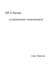
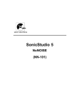
DS 2/4
digital speaker
management system
user manual
Musikhaus Thomann e. K.
Treppendorf 30
96138 Burgebrach
Germany
Telephone: +49 (0) 9546 9223-0
E-mail: [email protected]
Internet: www.thomann.de
26.10.2012
Table of contents
Table of contents
1
General notes............................................................................................................................................... 4
2
Safety notes.................................................................................................................................................. 7
3
Performance characteristics.............................................................................................................. 11
4
Installation and operation.................................................................................................................. 12
4.1 Pin assignment.................................................................................................................................. 13
5
Connectors and controls...................................................................................................................... 14
6
Functions..................................................................................................................................................... 19
7
Technical data........................................................................................................................................... 28
8
Protecting the environment.............................................................................................................. 30
DS 2/4
3
General notes
1
General notes
This user manual contains important information on safe operation of the device. Read and
follow all safety notes and all instructions. Save this manual for future reference. Make sure
that it is available to all persons using this device. If you sell the device to other users, be sure
that they also receive this manual.
Our products are subject to a process of continuous development. We therefore reserve the
right to make changes without notice.
Symbols and signal words
This section provides an overview of the symbols and signal words used in this user manual.
digital speaker management system
4
General notes
Signal word
Meaning
DANGER!
This combination of symbol and signal word
indicates an immediate dangerous situation
that will result in death or serious injury if it is
not avoided.
CAUTION!
This combination of symbol and signal word
indicates a possible dangerous situation that
can result in minor injury if it is not avoided.
NOTICE!
This combination of symbol and signal word
indicates a possible dangerous situation that
can result in material and environmental
damage if it is not avoided.
Warning signs
Type of danger
Warning – high-voltage.
DS 2/4
5
General notes
Warning signs
Type of danger
Warning – danger zone.
digital speaker management system
6
Safety notes
2
Safety notes
Intended use
This device serves sound control and distribution of incoming audio signals to the connected
speakers. Use the device only as described in this user manual. Any other use or use under
other operating conditions is considered to be improper and may result in personal injury or
property damage. No liability will be assumed for damages resulting from improper use.
This device may be used only by persons with sufficient physical, sensorial, and intellectual
abilities and having corresponding knowledge and experience. Other persons may use this
device only if they are supervised or instructed by a person who is responsible for their safety.
Safety
DANGER!
Danger for children
Ensure that plastic bags, packaging, etc. are disposed of properly and are not
within reach of babies and young children. Choking hazard!
Ensure that children do not detach any small parts (e.g. knobs or the like) from
the unit. They could swallow the pieces and choke!
Never let children unattended use electrical devices.
DS 2/4
7
Safety notes
DANGER!
Electric shock caused by high voltages inside
Within the device there are areas where high voltages may be present. Never
remove any covers.
There are no user-serviceable parts inside.
DANGER!
Electric shock caused by short-circuit
Always use proper ready-made insulated mains cabling (power cord) with a pro‐
tective contact plug. Do not modify the mains cable or the plug. Failure to do so
could result in electric shock/death or fire. If in doubt, seek advice from a regis‐
tered electrician.
digital speaker management system
8
Safety notes
CAUTION!
Possible hearing damage
With loudspeakers or headphones connected, the device can produce volume
levels that may cause temporary or permanent hearing impairment.
Do not operate the device permanently at a high volume level. Decrease the
volume level immediately if you experience ringing in your ears or hearing
impairment.
NOTICE!
Risk of fire
Do not cover the device nor any ventilation slots. Do not place the device near
any direct heat source. Keep the device away from naked flames.
DS 2/4
9
Safety notes
NOTICE!
Operating conditions
This device has been designed for indoor use only. To prevent damage, never
expose the device to any liquid or moisture. Avoid direct sunlight, heavy dirt, and
strong vibrations.
NOTICE!
Power supply
Before connecting the device, ensure that the input voltage (AC outlet) matches
the voltage rating of the device and that the AC outlet is protected by a residual
current circuit breaker. Failure to do so could result in damage to the device and
possibly injure the user.
Unplug the device before electrical storms occur and when it is unused for long
periods of time to reduce the risk of electric shock or fire.
digital speaker management system
10
Performance characteristics
3
Performance characteristics
n
n
n
n
n
n
n
n
n
Two inputs, four outputs (2 × 2-way, 3-way, 4-way, 2-way-sub)
Three digital 24-bit signal processors
Parametric five-band equalizers
High- and low-pass filters
Controllable input and output sensitivity
Runtime delay of up to seven seconds
Limiter with adjustable threshold, attack, hold and decay
RS232 interface
Installation in 19-inch racks (1 rack unit)
DS 2/4
11
Installation and operation
4
Installation and operation
Unpack and check carefully there is no transportation damage before using the unit. Keep the
equipment packaging. To fully protect the device against vibration, dust and moisture during
transportation or storage use the original packaging or your own packaging material suitable
for transport or storage, respectively.
Establish all connections as long as the unit is switched off. Use the shortest possible highquality cables for all connections.
Rack mounting
The unit has been designed for rack mounting in a standard 19-inch rack; it occupies one rack
unit.
digital speaker management system
12
Installation and operation
4.1 Pin assignment
XLR-connections for signal in-/
outputs
XLR mounting sockets are provided for signal inputs. XLR mounting plugs are provided for
signal outputs. The figure and the table show the XLR pin assignment for balanced wiring.
1
Ground
2
Positive signal (+)
3
Negative signal (–)
DS 2/4
13
Connectors and controls
5
Connectors and controls
Front panel
digital speaker management system
14
Connectors and controls
1 Display
2 BACK / NEXT
Cursor and navigation buttons. With the help of these buttons, you can place the cursor at the desired point in the
display text and switch between the different menus.
3 MENU
Button to call the menu function.
4 GAIN
Button to activate the parameterisation mode. Operate the button repeatedly to switch between the channels.
5 ENTER
Button to confirm changes and input values and to open the different submenus.
6 QUIT
Button to leave the opened menu or the menu function.
DS 2/4
15
Connectors and controls
7 Jog wheel
The jog wheel can be used to set parameters, enter values and select menu options.
8 LED-display input channel A / B
The LEDs show the signal strength of the input signal. Reduce the output level of the device connected to the
affected channel in the event of overdrive ("CLIP" LED flickers or is permanently lit).
9 LED-display output channel 1 to 4 with MUTE switch
The LEDs show the signal strength of the output signal. In the event of overdrive ("CLIP" LED flickers or is perma‐
nently lit), reduce the output level of the affected channel. The MUTE switch can be used to mute the channels indi‐
vidually; in this case, the associated display LED lights up.
10 Mains switch to activate/deactivate the device.
digital speaker management system
16
Connectors and controls
Rear panel
DS 2/4
17
Connectors and controls
11 Plug for mains cable with fuse holder.
12 RS232 interface, 9-pin D-SUB socket.
13 OUTPUTS
Signal output 4 to 1 (male XLR panel connector).
14 INPUTS
Signal input channel A and B (female XLR panel connector).
digital speaker management system
18
Functions
6
Functions
First switch on the speaker management system and then switch on the connected
devices to avoid activation crackling and possible damage to the connected speakers.
"Xover sub menu"
Operate the [MENU] button to open the "Xover sub menu". The settings of the crossover fre‐
quencies are stored in this menu.
"load a Xover"
This submenu permits calling of a stored configuration.
1.
Operate the [ENTER] button to activate the "load a Xover" option.
2.
Select the desired configuration with the jog wheel (1 to 10).
3.
Confirm your selection with [ENTER]. The display shows ‘loading …’ .
DS 2/4
19
Functions
"design a Xover"
A user configuration can be created in this submenu.
1.
Operate the [ENTER] button and then [NEXT] to activate the "design a Xover" option.
2.
Select the desired mode with the [NEXT] / [BACK] buttons or with the jog wheel, e.g.
"type: 2×2 way crossover“.
3.
Confirm the selection with [ENTER]. The display shows ‘out 3&4 source B’ . Use the [NEXT] /
[BACK] buttons or the jog wheel to select the desired channel assignment.
Since the channels cannot be freely assigned to the controller channels, the
sum formation function "source A+B" should not be assigned here. This can
lead to problems in stereo operation. The controller assigns the channels as fol‐
lows: INPUT A to OUTPUT 1 and 2, INPUT B to OUTPUT 3 and 4.
4.
Confirm your selection with [ENTER]. The display shows ‘stereo links: off’ . Use the [NEXT] /
[BACK] buttons or the jog wheel to select the desired option.
The "stereo links" option can be selected when the channels OP (OUTPUT) 1 and
3 as well as 2 and 4 are parameterised identically. The OUT1+3 and OUT2+4
values are then copied automatically and do not have to be entered repeatedly.
digital speaker management system
20
Functions
5.
"store a Xover"
Confirm the selection with [ENTER]. The display shows ‘new xover, ’ [ENTER] ‘to confirm’ .
This submenu permits saving the user-specific and changed configurations in the device.
1.
Operate the [ENTER] button and then twice the [NEXT] button to activate the "store a
Xover" option. The display shows ‘… store a xover’ .
2.
Operate the [ENTER] button and use the jog wheel to select the desired memory slot
(1 to 10).
3.
Operate the [ENTER] button. You may then select a user-specific designation. Use the jog
wheel and the [NEXT] button for this.
4.
Confirm the selection with [ENTER]. The display shows ‘stored’ .
DS 2/4
21
Functions
"erase a Xover"
"security sub menu"
Use this submenu to delete configurations stored in the device.
1.
Operate the [ENTER] button and then three times the [NEXT] button to activate the
"erase a Xover" option. The display shows ‘… erase a xover’ .
2.
Operate the [ENTER] button and select the memory slot of the configuration you want to
delete with the jog wheel (1 to 10). The display shows the safety prompt ‘erase xover
memory?’ .
3.
Confirm with [ENTER] to delete the configuration.
The "security sub menu" can specify the access rights for different device parameters to pre‐
vent undesired or unauthorised changes. The following options are available:
n
n
n
n
change only (read access to the parameters, MUTE function available)
change + view (no access to parameters, MUTE function available)
change + mute (read access to the parameters, MUTE function not available)
everything (no access to parameters, MUTE function not available)
Select the desired option with the [BACK] and [NEXT] buttons or the jog wheel and confirm the
selection with [ENTER]. The access lock can be revoked by input of a valid password.
digital speaker management system
22
Functions
Password input
Access to the different device parameters is password-protected. Proceed as follows to enter
the password:
n Push the [BACK] and [NEXT] buttons at once.
n Select one character at a time with the jog wheel and confirm each with [ENTER].
n Confirm the input of the last character again with [ENTER].
Then the device parameters can be changed as desired.
"setup“ menu
Different settings can be made in the setup menu.
"stereo Link"
The "stereo Link" function can be used to link two outputs. Confirm your selection with
[ENTER].
"wake up time"
The "wake up time" menu item can be used to determine the activation conduct of the digital
speaker management system. The following options are available:
n fade in (the outputs slowly move up to the set level at activation)
n mute hold (all outputs remain muted)
Confirm your selection with [ENTER].
DS 2/4
23
Functions
"delay time/distance"
The "delay time/distance" menu item can be used to set the runtime delay of the digital
speaker management system. Available units are meter (m), feet (ft) and milliseconds (ms).
Confirm your selection with [ENTER].
"interface“
The "interface" menu item can be used to determine the transfer sped of the RS232 interface
(2400, 4800, 9600, 19200 or 38400 Bd) and the device ID (Remote-ID 1 to 32) of the digital
speaker management system. Confirm your selection with [ENTER].
"name"
The"name" menu item can be used to assign designations from the present list to the outputs.
Select the desired designation with the jog wheel and confirm your selection with [ENTER].
"source“
The "source" menu item can be used to verify assignment of the inputs A and B. Changes are
not possible in this place.
"parameter" menu
In the "parameter" menu, different device parameters can be adjusted. Open the menu with
[GAIN], select the desired option with the [BACK] and [NEXT] buttons and confirm the selection
with [ENTER]. The access lock can be revoked by input of a valid password.
digital speaker management system
24
Functions
Parameter
Function
Value range
Input gain
Input amplification
–40 … +6 dB
Output Gain
Output amplification
–40 … +6 dB
Output Phase
Polarity
+/–
This parameter can be used to com‐
pensate for possible phase errors
(deletion of certain frequency
areas) at the outputs by phase
reversal.
Delay
Runtime delay
0…7s
This parameter can be used to com‐
pensate for constructively caused
different signal runtimes of
speakers or spatially caused run‐
time differences (speaker distance).
High Pass
High-pass filter
< 10 Hz…16 kHz
Low Pass
Low-pass filter
35 Hz … 22 kHz
DS 2/4
25
Functions
Equalizer
A parametric 5-band equalizer is available per output. Additionally, a high- or low-shelf filter
can be set. For this, set the gain to 0 dB and the Q-factor to "Hishelf/Loshelf". To deactivate a
certain EQ-band (bypass mode), push the [ENTER] button.
Parameter
Value range
Frequency
20 Hz … 20 kHz
Q-factor
0,5…10
Gain
±12 dB, ±1 dB
High-Shelf
1 kHz … 20 kHz
Low-Shelf
20 Hz … 1 kHz
digital speaker management system
26
Functions
Limiter
There is a limiter available for each output. These limiters limit the signal level for each channel
to a specific threshold and therefore offer additional protection against overdrive and damage
to the connected speakers.
Parameter
Function
Value range
Threshold
Threshold
–20 … +15 dB
Attack
Attack time
1 … 100 ms
Hold
Holding time
0 … 100 ms
Decay
Decay time
10 … 1000 ms
DS 2/4
27
Technical data
7
Technical data
Input impedance
10 kΩ
Common-mode rejection ratio (CMRR)
> 50 dB (30 Hz…20 kHz)
Output impedance
< 50 Ω
Max. voltage difference between positive and
negative peak voltage
Vpp = 4 V, Vpp = 7.6 V
Frequency response
20 Hz … 20 kHz
Total harmonic distortion (THD)
0,01 %
Maximum runtime delay
7 ms
Output amplification
–40 dB … +6 dB (±0.5 dB)
Input amplification
–40 dB … +6 dB (±0.5 dB)
Mains power supply
90 V … 230 V
(AC), 50/60 Hz
digital speaker management system
28
Technical data
Dimensions (H × W × D)
44 mm × 480 mm × 220 mm (1.73 in. × 19.90 in. × 8.67 in.)
Weight
3.6 kg (7.94 lbs.)
DS 2/4
29
Protecting the environment
8
Protecting the environment
Disposal of the packaging mate‐
rial
For the transport and protective packaging, environmentally friendly materials have been
chosen that can be supplied to normal recycling.
Ensure that plastic bags, packaging, etc. are properly disposed of.
Do not just dispose of these materials with your normal household waste, but make sure that
they are collected for recycling. Please follow the notes and markings on the packaging.
Disposal of your old device
This device is subject to the European directive 2002/96/EC.
Do not dispose of the device with your normal household waste.
Dispose of this device through an approved waste disposal firm or through your local waste
facility. When discarding the device, comply with the rules and regulations that apply in your
country. If in doubt, consult your local waste disposal facility.
digital speaker management system
30
Musikhaus Thomann e.K. · Treppendorf 30 · 96138 Burgebrach · Germany · www.thomann.de