1
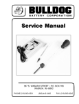
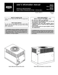
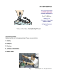
1
Avai
l
abl
eFr
om:
Sol
ar
Panel
St
or
e.
com
USERS MANUAL
Solar-One® Battery System
Table of Contents
Precautions and receiving the battery
Installation and initial charge
Page 2
Pages 3 & 4
General Maintenance
Page 5 –7
Charts and Graphs
Page 8
Specifications
Page 9
Recharge Settings
Page 10
Diagrams
Pages 11 & 12
Troubleshooting
Page 13
Maintenance Guidelines
Page 14
Warranty
Page 15
Water Warning
Page 16
Copyright Northwest Energy Storage Inc. 2011-2012 Revised 08/22/11
Tech support 941-474-0110 M-F 9am-5pm central time.
2
Precautions and Warnings
Batteries contain sulfuric acid (which causes severe burns) and while being charged, emit hydrogen gas which is
explosive. You must always assume the battery is emitting hydrogen gas. Batteries are always electrically live
and will deliver very large amounts of current if shorted. To reduce the risk of personal injury and/or harm to
property and the environment follow the precautions below.
Do not smoke, use open flames, or create an electrical arc or spark in the vicinity of the battery.
Use insulated tools, remove all jewelry, wear protective clothing and eye/face protection when working on
batteries.
If you get battery acid in your eyes immediately flush with clear water for 15 minutes and seek medical
attention. Do not use neutralizing agent in your eyes.
Always keep a solution of neutralizing agent on hand. (1 gal. Of water thoroughly mixed with 1 lb. Of baking soda) use this agent to neutralize any acid that may get on your skin or clothing and for general battery cleaning. Rinse with clear water when bubbling stops.
Ensure the battery compartment is well ventilated. When powerventing devices are used, ensure that they
are functioning properly.
Only use the cell lifting strap provided to remove cells from the tray. If the battery is to be installed with
all cells in the tray, cover the cell terminals with a non conductive material such as plywood or a thick rubber material.
Only persons who are trained to maintain, install and care for batteries should be allowed to work with
the battery.
Only use distilled or deionized water and do not over fill.
Receiving the Battery
Immediately inspect the exterior of the packaging,
including the pallet. Look for wet spots or stains that
would indicate the battery was damaged or tipped over
during transit. If there is visible evidence of damage
you should make a note on the shipping papers
“SHIPMENT RECEIVED DAMAGED”. Refuse the
shipment and notify your Solar-One dealer. Shipping
damage is not covered under the battery warranty.
Photographs of the damage will be very helpful.
When the shipment is received and there is no visible
damage, but damage is found during unpacking,
immediately file a “CONCEALED DAMAGE
REPORT” with the shipper and notify your Solar-One
dealer. Shipping damage is not covered under the
battery warranty. Photographs of the damage will be
very helpful.
Your Solar-One Battery is packaged by professionals using quality materials to DOT specifications. If the
condition of your shipment is not received reasonably close to the above photo, contact your Solar-One Dealer or
call 941-474-0110.
Tech support 941-474-0110 M-F 9am-5pm central time.
3
Installation
Step 1
Acquire the following safety items: safety glasses or face shield, acid resistant apron, insulated
1/2” wrench, insulated ratchet with 1/2” socket, 1 gal neutralizing agent, ( 1 lb baking soda to 1 gal. water, mix this
solution thoroughly) rubber gloves
Step 2
Inspect the battery tray (steel case) for evidence of damage, if damage has occurred file a claim
with the carrier immediately. If you see liquid on the top of the cells pour some neutralizing agent into a small
container and apply with a clean paint brush. Be extra careful not to get any of this agent into the cell. Apply
this agent to the terminals and the cell tops until bubbling stops. Rinse with clear water and wipe dry.
Note: If the battery can be installed without removing the cells, connect a chain to the holes on the end of the
tray. Be sure the lid is closed and that a non conductive material such as plywood or thick rubber covers
the terminals. Use a 2x4 wood spreader that is approx. 1/2” shorter than the tray. The spreader will
prevent end pressure on the tray.
If the battery cannot be installed without removing the cells because of weight concerns proceed
to step 3 skipping step 6.
Step 3
Remove the tray lid by tapping one hinge back into the lid hinge, or remove the internal hex bolts.
Warning:
Do not allow the lid to fall onto the terminals as this could cause shorting from terminal to
terminal. Cover the cell terminals with a nonconductive material such as plywood or a
thick rubber material, etc.
Step 4
Remove the buss bars.
Caution:
These cells can be extremely heavy, a comealong or block and tackle may be needed to
do the lifting. Do not try lifting these cells by
yourself, serious injury could occur.
Note: As you remove the cells from the tray you may notice
the electrolyte level is low. DO NOT add water to
the cells, this condition is normal. See “Initial Charge”
section on the next page.
Step 5
Connect the cell lifting strap into the holes of the terminals that are inline with the round post
that protrude from the case. (see photo below) Lift the cells out of the tray. The first cell out of the tray will be
harder than the remaining cells. If you find the first cell very hard to remove try another cell or lubricate with
soapy water. If the clevis on the cell lifting strap will not slide over the terminal, slightly spread the clevis.
Warning:
The weight of the cells will cause the sides to bulge when removed from the tray, this
is normal, however use caution when handling the cells. Any pressure on the sides will cause the
cells to “breathe” and can release small droplets of electrolyte in the area of the cap. Placing a
cloth over the vent cap will reduce this hazard. To prevent serious and permanent damage to the
battery, do not leave the cells out of the “tray” for more than 24 hours.
Tech support 941-474-0110 M-F 9am-5pm central time.
4
Installation cont.
Warning:
Never allow tools or other conductive objects to make contact with two or more battery
terminals.
Step 6
Neutralize the sides of the cells and the steel tray. Rinse and dry thoroughly.
Step 7
Move the steel tray to the desired location.
Step 8
Install the cells back into the tray using the diagram on page 12 to ensure the cells are correctly
installed. The cells must be completely seated in the tray to properly install the cell interconnects. All plastic
spacers must be reinstalled when the battery is reassembled.
Step 9
Referring to the diagrams on page 12 install the nuts and bolts in the exact pattern as shown.
Torque all bolts to 40 in. lbs. and re-torque annually.
Step 10
Install the lid by tapping the hinge pin back into the tray hole. When you install the lid you have
a choice of where the hinges are located. Some lid hinges use a internal hex head bolt, use an Allen wrench to
remove and replace the lid.
Initial Charge
The battery ships from the factory with a minimum specific gravity of 1.265. However when received, the electrolyte level may be low and have a lower than 1.265 reading. This has to do with shipping, handling and hot temperatures in trucks. Prior to adding water, charge the battery at 15 volts for a 12 volt system, 30 volts for a 24 volt
system, and 60 volts for a 48 volt system. The charge should be applied until the electrolyte level rises to the normal level or slightly lower, and a full gravity of 1.280 is achieved. Label each cell, check the specific gravity and
voltage of all cells, and enter the information in the area provided below.
Cell ID.
Volts
Specific Gravity
Cell ID.
Volts
Tech support 941-474-0110 M-F 9am-5pm central time.
Specific Gravity
5
General Maintenance
Warning:
Always wear protective clothing and eye/face protection when working around batteries. If you
should get acid in your eyes or on your skin, flush with clear water for 15 minutes and seek
medical help. Do Not use neutralizing agent to flush your eyes!
Adding Water
Fill to: 1/4" (+/-) from the bottom of the filler neck throat. (See cell drawing below) A flashlight will make adding
water much easier. Putting a full level mark on the hydrometers rubber tube will be helpful too.
A certain amount of fluid loss is normal in all batteries, and must be replaced at regular intervals with distilled or
deionized water. Over-filling is one of the most common errors made during battery maintenance and will cause
gradual lowering of the specific gravity and a subsequent loss of capacity, corrosion to the tray and the intercell
connectors. Add water after the battery has finished charging and after taking hydrometer readings. If the battery
is subjected to freezing temperatures it is a good idea to add water when the battery is reaching appx. 75% charged
or 1 hour before ending an equalize charge. It can take up to several days for the newly added water to mix with
the rest of the acid, this water could freeze before mixing with the electrolyte.
Warning:
Do Not Overfill. Do Not Use Tap Or Well Water they may contain small amounts of nickel,
iron, manganese, copper, chlorine, nitrates, etc. These and other minerals can seriously affect
battery life and may void your warranty.
Flip Top
Filler Cap
Cell Lid
1” +/1/4” +/-
Filler Neck Throat
Cell Jar
1/4” +/-
Full
Low
1 1/4” +/-
Approx. 25”
Electrolyte
3 1/4”
1/2” +/-
3/4” +/-
Tech support 941-474-0110 M-F 9am-5pm central time.
6
General Maintenance
Using a Hydrometer:
Insert the rubber tube into the cell, but not into the electrolyte. Squeeze the bulb and lower the rubber tip
into the electrolyte, now release the pressure from the bulb. The barrel will fill up and the float will rise. It is very
important for the float to be freely suspended in the electrolyte. Gently move the hydrometer back and forth until
the float is not in contact with the barrel. Where the numbers on the float intersect with the top of the electrolyte is
the specific gravity. See the following section for interpreting your hydrometer readings. With the rubber tip in
the cell, but not submersed into the electrolyte squeeze the bulb and drain the electrolyte back into the cell. Wipe
dry any spilled electrolyte. We recommend the NAPA 700-1145 hydrometer.
Specific Gravity:
The standard fully charged specific gravity for the Solar-One is 1.275-1.285 @ 77° F the 100%
discharged gravity is 1.140 @ 77° F. Since the acid content of the electrolyte decreases linearly as the cell is
discharged, the decrease in gravity is directly proportionate to the amount in ampere-hrs taken out. The specific
gravity at any point in the discharge indicates the depth of discharge, and can be translated into ampere-hrs taken
out. Knowing that the fully charged specific gravity is 1.280 and the discharged specific gravity is 1.140 we can
find our state of discharge.
Example: Assume the specific gravity is 1.180. 1.180 is 100 points below the fully charged specific
gravity of 1.280. With a difference of 140 points from 100% charged to 100% discharged we can divide 100/140 =
71% discharged. Use this formula to help keep your Amp/Hr meter synchronized with your battery.
Warning:
All Lead-Acid batteries are considered discharged when 80% of the capacity has been removed.
Never remove more than 80% of the battery capacity.
Temperature:
Lead-acid batteries are a chemical reaction, and when subjected to different temperatures will produce
different results. The normal operation temperature 77-80°F. Lower than normal temperatures will reduce
capacity, slightly extend life, require a higher recharge voltage, and cause specific gravity readings to be adjusted
down, from the actual reading. Higher temperatures have the opposite effect. Correction tables can be found on
page 8 of this manual.
Note:
Most inverters or charge controllers use a battery temperature sensor, secure the probe to the
lead interconnect where the terminals penetrate the cell. Use the most central cell of your
battery.
Equalize Charge:
The term “equalize” simply means a controlled overcharge. This procedure is used to adjust the
difference between cells that develop due to temperature variations within the battery, manufacturing, and cycling
of the battery. The equalize charge will also help scrub off sulfate particles that tend to build-up on the positive
plate of the battery. When to equalize: If a cell has a .020 difference in specific gravity or at least once a month.
How to equalize: Generally you continue the bulk charge for an additional 2-3 hours after the battery has become
full. The equalize charge rate should be appx. 2% - 5% of the battery capacity. This will tend to raise the battery
voltage 1-1.5 volts above the bulk setting. Ensure that any sensitive loads can accept this higher voltage.
Tech support 941-474-0110 M-F 9am-5pm central time.
7
General Maintenance
Voltage
There is a definite relationship between the cell voltage and the specific gravity of a cell that is open
circuit (no charging or discharging for at least 24 hours). These open circuit voltage readings are useful in
determining uniformity. A fully charged open circuit with a specific gravity of 1.260 - 1.280 will read 2.10 volts
per cell to 2.12 volts per cell at 77°F. This spread of .02 vpc is considered normal for a new battery As the battery
ages the spread will increase to about .03 to .05 vpc.
If all cells of a battery show similar full-charge voltages, they are equally healthy. The uniformity and
value of the individual cell voltage readings vary with the overall condition of the battery. A battery with an oncharge voltage of 2.45 to 2.50 volts per cell has more uniformly healthy cells than a battery having an on-charge
voltage spread of 2.40 to 2.50 volts per cell. The age and service duty of the battery must be considered in the
interpretation of the on-charge voltage readings. An example would be an older battery which has on-charge cell
voltage readings of 2.45 volts to 2.65 volts. The reason may very well be that the inside cells operate at higher
than average temperatures causing higher local action, which would result in lower voltage. Regular equalize
charging will compensate for the higher self-loss of the inside cell. Any wide spread in on-charge voltage that
could not be attributed to the service life or age of the battery, is a sign that something is wrong and attention is
necessary. Some causes of abnormally wide spread or charge voltages are: Abnormal temperature differential,
internal shorts, acid loss causing overdischarge, insufficient charging, and insufficient equalize charging.
Sulfation
All lead-acid batteries sulfate when discharged. The active material must convert to lead sulfate in order for the
cells to produce energy. The term sulfated battery means that the battery has developed abnormal sulfate and has
its capacity reduced as a result. The most common causes of sulfation are:
1.
2.
3.
4.
5.
6.
Under charging or neglect of equalize charge.
Standing in a partially or completely discharged condition.
Low electrolyte level.
Adding battery acid.
High specific gravity.
High temperature.
Cells of a sulfated battery give a low specific gravity and voltage readings and the battery will not become fully
charged after a regular equalize charge. Before assuming that the battery is sulfated, rule out the possibility that
low specific gravity may be due to acid loss. If the sulfation has not progressed too far, it may be possible to return
the battery to a serviceable condition by paying careful attention to the following:
(A) Neutralize, wash and dry the battery.
(B) Add distilled or deionized water to the proper level.
(C) Charge the battery at 2% of its 6 hr capacity until 100% of the battery’s capacity has been restored. The 6 hr
capacity is on the label on one end of your battery.
(D) Discharge the battery to 1.75 volts per cell (10.5 for 12 volt systems, 21 for 24 volt systems or 42 for 48 volt
systems) making sure not to allow any cells to drop below 1.75 volts or cell reversal may occur. Cell reversal can
be identified by very high cell voltage (3-4 volts) while on charge, or very low cell voltage (1 volt or less) while
being discharged.
(E) Recharge until the specific gravity is the same for 3 hours.
(F) Repeat the process until the specific gravity remains constant. If the battery gives 80% or more you have
succeeded, if not, replace the battery.
Warning:
Do not let your battery stand in a discharged state for more than 24 hours or when temperatures
are below freezing.
Tech support 941-474-0110 M-F 9am-5pm central time.
8
Charts and Graphs
Specific Gravity Vs.
Percent Discharged
1.280
Specific Gravity
Temperature Correction
Cell Voltage
Temperature Correction
Freezing points of
battery Electrolyte
Electrolyte
Temperature
Hydrometer
Correction
Electrolyte
Temperature
Cell Voltage
Correction
Electrolyte
Temperature
Specific
Gravity
1.260
49-51 °F
-.009
49-51 °F
-.09
32 °F
1.000
1.240
52-54 °F
-.008
52-54 °F
-.08
25 °F
1.050
55-57 °F
-.007
55-57 °F
-.07
18 °F
1.100
58-60 °F
-.006
58-60 °F
-.06
14 °F
1.125
61-63 °F
-.005
61-63 °F
-.05
5 °F
1.150
64-66 °F
-.004
64-66 °F
-.04
-4 °F
1.175
1.220
1.200
1.180
67-69 °F
-.003
67-69 °F
-.03
-15 °F
1.200
1.160
70-72 °F
-.002
70-72 °F
-.02
-23 °F
1.210
1.140
73-75 °F
-.001
73-75 °F
-.01
-33 °F
1.220
76-78 °F
No Correction
76-78 °F
No Correction
-42 °F
1.230
79-81 °F
+.001
79-81 °F
+.01
82-84 °F
+.002
82-84 °F
+.02
85-87 °F
+.003
85-87 °F
+.03
Temperature
Capacity
88-90 °F
+.004
88-90 °F
+.04
77 °F
100%
91-93 °F
+.005
91-93 °F
+.05
60 °F
95%
94-96 °F
+.006
94-96 °F
+.06
50 °F
91%
97-99 °F
+.007
97-99 °F
+.07
40 °F
87%
100-102 °F
+.008
100-102 °F
+.08
30 °F
81%
20 °F
74%
1.120
0 10 20 30 40 50 60 70 80 90 100
% Discharged
Tech support 941-474-0110 M-F 9am-5pm central time.
Temperature Effects on
Battery Capacity
Solar-One Specifications
9
Rated
A/H
(20 hr)
Rated
A/H
(6 hr)
Usable
A/H
(20 hr)
Rated
Watt/hrs
(20 hr)
Usable
Watt/hrs
(20 hr)
SO-6-85-17/12
845
680
676
10,140
8,112
68 amps
SO-6-85-19/12
950
765
760
11,400
9,120
SO-6-85-21/12
1055
850
844
12,660
SO-6-85-23/12
1160
935
928
SO-6-85-25/12
1270
1020
SO-6-85-27/12
1375
SO-6-85-31/12
LxWxH
in Inches
Weight
in Lbs.
Short Circuit
Ratings in Amps
@ 104°F
136 amps
40 x 7.75 x 25
742
9,600
76.5 amps
153 amps
40 x 8.55 x 25
808
10,800
10,128
85 amps
170 amps
40 x 8.75 x 25
880
12,000
13,920
11,136
93.5 amps
187 amps
40 x 9.00 x 25
959
13,300
1016
15,240
12,192
102 amps
204 amps
40 x 10.25 x 25
1036
14,400
1105
1100
16,500
13,200
110.5 amps 221 amps
40 x 11.25 x 25
1102
15,600
1585
1275
1268
19,020
15,216
127.5 amps 255 amps
40 x 12.75 x 25
1252
18,000
SO-6-85-33/12
1690
1360
1352
20,280
16,224
136 amps
272 amps
40 x 13.5 x 25
1336
19,200
SO-6-100-33/12
1990
1600
1592
23,880
19,104
160 amps
320 amps
40 x 13.5 x 28
1550
22,600
SO-6-125-33/12
2490
2060
1992
29,880
23,904
206 amps
412 amps
40 x 13.5 x 33
1698
29,100
Rated
A/H
(20 hr)
Rated
A/H
(6 hr)
Usable
A/H
(20 hr)
Rated
Watt/hrs
(20 hr)
Usable
Watt/hrs
(20 hr)
*Min.
Charging
System
*Max.
Charging
System
L x W x H in Inches
Depending on how configured
Weight
in Lbs.
Short Circuit
Ratings in Amps
@ 104°F
SO-6-85-17/24
845
680
676
20,280
16,224
68 amps
136 amps
80 x 7.75 x 25 or 40 x 15.5 x25
1484
9,600
SO-6-85-19/24
950
765
760
22,800
18,240
76.5 amps
153 amps
80 x 8.25 x 25 or 40 x 16.5 x 25
1616
10,800
SO-6-85-21/24
1055
850
844
25,320
20,256
85 amps
170 amps
80 x 8.75 x 25 or 40 x 17.5 x 25
1760
12,000
SO-6-85-23/24
1160
935
928
27,840
22,272
93.5 amps
187 amps
80 x 9.00 x 25 or 40 x 18.00 x 25
1918
13,300
SO-6-85-25/24
1270
1020
1016
30,480
24,384
102 amps
204 amps
80 x 10.25 x 25 or 40 x 20.5 x 25
2072
14,400
SO-6-85-27/24
1375
1105
1100
33,000
26,400
110.5 amps 221 amps
80 x 11.25 x 25 or 40 x 22.5 x 25
2204
15,600
SO-6-85-31/24
1585
1275
1268
38,040
30,432
127.5 amps 255 amps
80 x 12.75 x 25 or 40 x 25.5 x 25
2504
18,000
SO-6-85-33/24
1690
1360
1352
40,560
32,448
136 amps
272 amps
80 x 13.5 x 25 or 40 x 27.0 x 25
2672
19,200
SO-6-100-33/24
1990
1600
1592
47,760
38,208
160 amps
320 amps
80 x 13.5 x 28 or 40 x 27.0 x 28
3100
22,600
SO-6-125-33/24
2490
2060
1992
59,760
47,808
206 amps
412 amps
80 x 13.5 x 33 or 40 x 27 x 33
3396
29,100
Rated
A/H
(20 hr)
Rated
A/H
(6 hr)
Usable
A/H
(20 hr)
Rated
Watt/hrs
(20 hr)
Usable
Watt/hrs
(20 hr)
*Min.
Charging
System
L x W x H in Inches
Depending on how configured
Weight
in Lbs.
Short Circuit
Ratings in Amps
@ 104°F
SO-6-85-17/48
845
680
676
40,560
32,448
68 amps
136 amps
160 x 7.75 x 25 or 80 x 15.5 x 25
Or 40 x 31 x 25
2968
9,600
SO-6-85-19/48
950
765
760
45,600
36,480
76 amps
153 amps
160 x 8.25 x 25 or 80 x 8.25 x 25
or 40 x 33 x 25
3232
10,800
SO-6-85-21/48
1055
850
844
50,640
40,512
85 amps
170 amps
160 x 8.75 x 25 or 80 x 18.00 x 25
or 40 x 36.00 x 25
3520
12,000
SO-6-85-23/48
1160
935
928
55,680
44,544
93 amps
187 amps
160 x 9.00 x 25 or 80 x 18.00 x 25
or 40 x 35.00 x 25
3836
13,300
SO-6-85-25/48
1270
1020
1016
60,960
48,768
102 amps
204 amps
160 x 10.25 x 25 or 80 x 20.5 x 25
or 40 x 41.0 x 25
4144
14,400
SO-6-85-27/48
1375
1105
1100
66,000
52,800
110 amps
221 amps
160 x 11.25 x 25 or 80 x 22.5 x 25
or 40 x 45.0 x 25
4408
15,600
SO-6-85-31/48
1585
1275
1268
76,080
60,864
127 amps
255 amps
160 x 12.75 x 25 or 80 x 25.5 x 25
or 40 x 51.0 x 25
5008
18,000
SO-6-85-33/48
1690
1360
1352
81,120
64,896
136 amps
272 amps
160 x 13.5 x 25 or 80 x 27.0 x 25
or 40 x 54.0 x 25
5344
19,200
SO-6-100-33/48
1990
1600
1592
95,520
76,416
160 amps
320 amps
160 x 13.5 x 28 or 80 x 27.0 x 28
0r 40 x 54.0 x 28
6200
22,600
SO-6-125-33/48
2490
2060
1992
119,520
95,616
206 amps
412 amps
160 x 13.5 x 3 or 80 x 27 x 33
or 40 x 27 x 33
6792
29,100
Model #
12 Volts
Model #
24 Volts
Model #
48 Volts
*Min.
Charging
System
*Max.
Charging
System
*Max.
Charging
System
* The Charging System is the sum of all charging sources including, but not limited to: Solar, Wind, Hydro generator, Inverter/
support
941-474-0110 M-F 9am-5pm central time.
Charger, DC generator, or stand aloneTech
battery
charger.
10
Solar-One® Specifications
24 hr. Open Circuit Volts vs. Depth of Discharge (DOD)
DOD
12 volts
24 volts
48 volts
Specific Gravity
12.75
25.50
51.00
1.275-1.285
30%
12.36
24.72
49.44
1.236
50% (Half Discharged)
12.12
24.24
48.48
1.205
70%
11.88
23.76
47.52
1.181
80% (Considered Dead)
11.76
23.52
47.04
1.168
0%
(Full Charged)
The above values must be taken with no charge or discharge (Open Circuit) on the battery for a
minimum of 24 hours. The temperature must be at 77°F and you must use a very accurate Digital Multi Meter.
Recharge Settings
12 volt
24 volt
48 volt
Bulk
14.4—14.8
28.8—29.6
57.6—59.2
Equalize
15.0—15.5
30.0—31.00
60—62
Float
13.50
27.0
54.0
Absorption time
2 hrs.
2 hrs.
2 hrs.
Equalize time
2 hrs.
2 hrs.
2 hrs.
These recharge voltage settings are ball park settings that will work for most systems. Use the
lower values if cycling is shallow and/or infrequent, use the higher values if the cycling is moderate to deep and frequent. If you find your specific gravity is not reaching 1.275-1.285 raise
the voltage settings by .1 volt increments until the specific gravity readings indicate a fully
charged battery. You can also increase the absorption time to correct low specific gravity. If the
battery uses an excessive amount of water or is overheating lower the settings by .1 volt
increments until the overcharge is removed.
Warranty
Cycles To 80% DOD
Battery Type
Positive Plate
Positive Plate Thickness
Post-to-Cover Seal
Cell “Jar” Material
Cell Cover Material
Tray Material
Intercell Connectors
Specific Gravity @ 77°F
Maximum Temperature
10 Years 7 years free replacement 3 years prorated
2100 Over 10 Years
Flooded Lead-Acid
Tetrafluoroethylene (Teflon®) /Lead Antimony
.031”
Burned Post to Cover
Injection Molded Polypropylene
Polypropylene
Epoxy Coated Steel
Lead-Plated Copper Rated @ 230 Amps
1.285-1.275 Fully Charged 1.160 80% Discharged
105°F
Gallons of Electrolyte Per Cell
6-85-17=1.7 6-85-19=1.9 6-85-21=2.1 6-85-23=2.2 6-85-25=2.5
6-85-27=2.7 6-85-31=3.1 6-85-33=3.3 6-100-33=3.7 6-125-33=4.2
Tech support 941-474-0110 M-F 9am-5pm central time.
11
Diagrams
12 Volt All Models
12 V Neg.
12 V Pos.
2 (Two Paralleled) 12 Volt All Models
12 V Neg.
12 V Pos.
Note:
Each tray of Solar-One® batteries comes with an extra lead coated copper buss bar. This
bar is to be used for making a parallel connection as shown above, or a series connection as
seen on the next page. This bar is bent on site and can be a “horse shoe” (above) or a
“Z” (next page) configuration. When bending the bar use a smooth radius instead of sharp
bends. Sharp bends tend to stretch the backside of the copper making it less effective in the
transfer of energy.
Tech support 941-474-0110 M-F 9am-5pm central time.
12
Diagrams
24 Volt All Models
48 Volt All Models
4/0 Series Cable
48 Volt Positive
Tech support 941-474-0110 M-F 9am-5pm central time.
13
Troubleshooting
Problem
Probable Cause
Remedy
Battery not performing as
expected
Battery is undersized.
Replace with a larger battery.
Battery not fully charged
Check charger and controller.
Weak or defective cells.
Perform a load test
Grounds or shorts.
Clean battery and all connections in the system
Phantom loads in system
Find and eliminate loads.
Battery is spent.
Replace battery.
Improper equipment settings
Adjust charging equipment.
Malfunction of charging equipment
Verify charging equipment output.
Battery too deeply discharged
Limit discharge to 80% DOD.
High resistance connection.
Check for hot connections.
Battery room too warm.
Provide cooler battery room.
Low electrolyte level
Add water to correct level allow to cool and recharge
Weak or defective cells.
Repair or replace cell
Battery is spent
Replace battery
Excessive load.
Reduce loads. Need larger battery
Battery not fully recharged
Let battery cool. Do a load test
Battery over discharged
Limit discharge to 80% DOD
Battery room too warm.
Provide cooler battery room
Lack of watering.
More care required
Frequent overcharging
Adjust/check charging system
Spilled electrolyte
Add water, equalize and adjust specific gravity
(contact dealer)
Cracked or broken jars
Replace jars.
Overdischarging
Perform equalize charge
Acid loss due to over-watering or spillage
Perform equalize charge and adjust specific gravity
Corroded or dirty tops
Neutralize and clean tops
Grounds in battery
Clean battery
Impurities in electrolyte
Use only distilled water
Battery used infrequently
Deep discharge and equalize
Weak or defective cells.
Repair or replace battery
Lack of equalize charges
Equalize more often
All the above
All the above
Recently added water
Gassing will mix new water
Improper gravity adjustment after cell
replacement
Adjust specific gravity (contact your dealer)
Battery overheats on charge.
Battery overheats on discharge
Low electrolyte level
Unequal cell voltages.
Unequal Specific Gravity
Tech support 941-474-0110 M-F 9am-5pm central time.
14
Maintenance
Below are guidelines for maintenance of the Solar-One® Battery. Your previous knowledge of lead-acid batteries
may not require this much attention, but remember, the more interaction you have with the battery (The Heart of
the system) the better service life you can expect from your investment.
The Solar-One® warranty as it pertains to records, only requires that "reasonable records be kept". Use your best
judgement.
Bi-Weekly
(Every other week)
1.
2.
3.
4.
5.
Record hydrometer reading of pilot cell (the cell with the lowest specific
gravity when you first received the battery. Once a year select a different
cell to be the pilot cell)
Check the electrolyte level (add distilled or deionized water as needed.)
Record Amp/Hrs Consumed from your A/H Meter
Inspect for loose or corroded connections (clean and tighten as needed)
Ensure the battery has been fully charged at least two (2) times per week
Monthly
1.
2.
3.
4.
Clean battery with a damp cloth. (If battery tops are wet with acid
use neutralizing agent with a clean paint brush, dry thoroughly.)
Equalize the battery
Check the electrolyte level (add distilled or deionized water as needed.)
Inspect for loose or corroded connections (clean and tighten as needed)
Bi-Monthly
(Every Other Month)
1.
Record hydrometer readings of all cells (after the battery is fully charged.)
A. If the average readings are less than 1.275 - 1.285 check all
charging sources and adjust as needed.
B. If one or two cells read .020 points less than the average,
circle those readings and check for improvement the next time the
battery becomes fully charged. If the low cells do not improve, the
cells are in need of an equalize charge.
Yearly
1.
Torque all terminal bolts.
Tech support 941-474-0110 M-F 9am-5pm central time.
15
IND-262 REV D 07/05
Hup.® Solar-One®
WARRANTY AND ADJUSTMENT AGREEMENT COVERING
HUP® SOLAR ONE®BATTERIES FOR RENEWABLE ENERGY
Sold to
__________________________________________
Shipped To _____________________________________________
Charger Type
__________________________________________
Locaon
Date Shipped
__________________________________________
Serial Number___________________________________________
_____________________________________________
®
EnerSys® Delaware Inc. (“EnerSys”) warrants all General Baery™ Hup® Solar-One baeries to be free from defects in workmanship and
materials for the period stated in the following table, from the date of installaon or no more than three (3) months from date of shipment, whichever comes first.
1
2
Total Warranty Period
Full Credit,
Parts, Labor1, Freight2
Full Credit,
Parts Only
Prorated Credit
120 Months
First 12 Months
13 Through 84 Months
85 Through 120 Months
Service Center labor only. On-site labor is not covered.
Covers freight to and from the Service Center or part replacement shipment to user. It does not include transportation charges for on-site service.
If the battery fails to deliver 80% of its rated capacity at the 20-hour rate within 84 months due to defects in workmanship or materials, the defective parts will be replaced by EnerSys® exclusive of labor and freight.
In addition, if the battery fails to deliver 80% of its rated capacity at the 20-hour rate after 84 months, EnerSys ® will credit Northwest Energy an amount equal in dollars
to the net purchase price of the original battery, multiplied by the months of unexpired life, divided by the number of months in the period stated above. Credit will be against the
purchase of another Hup® Solar-One® battery of equal or greater KWH capacity.
This warranty is subject to the following terms and limitations.
1. The User, Northwest Energy Storage and EnerSys ® mutually agree the battery identified above must be sized properly to perform the duty cycle originally intended.
The battery must not be required to perform a duty cycle in excess of the originally intended one.
2. The battery must be maintained in accordance with Northwest Energy Storage’s current published Operating and Maintenance instructions. The operator of the Renewable Energy (RE) system must keep reasonable records of use and maintenance. Failure to monitor watering intervals, discharges and full recharge may void
warranty coverage.
3. Use of each battery must be limited to no more than four (4) 80% depth of discharge cycles per 7-day week and no more than 210 cycles per calendar year. If these
amounts are exceeded, the months of warranty will be reduced.
4. The battery must be charged on a properly sized charging system capable of delivering 10% to 20% of the battery AH charge rate. The “charging system” is defined
as the sum total of all charging sources. Use of a constant voltage charge controller is prohibited.
5. All RE systems must have an AH metering device installed in accordance with the manufacturer’s installation manual.
6. Use only distilled or deionized water. The use of electrolyte additives or compounds voids all warranty coverage.
7. This warranty does not cover physical damage due to acts of nature or man, which stress the battery beyond design limits and exert undesirable influence aside from
normal wear and tear. This warranty is void if the battery is subjected to misuse, physical damage or abuse other than normal wear and tear.
8. EnerSys assumes no responsibility for any work accomplished or expenses incurred except with express written consent.
9. This warranty applies to the original purchaser (User) of the battery and is nontransferable. This warranty covers products situated only in North America.
10. EnerSys, at its option, may require proof of purchase consisting of a copy of the original invoice.
EnerSys® shall not be liable for indirect, incidental or consequential damages arising out of sale or relating to the use of this product. The purchaser assumes responsibility for all
personal injury and property damage resulting form the handling, possession or use of the product. In no event shall the liability of EnerSys for any and all claims, including claims
of breech of warranty or negligence, exceed the purchase price of the product.
THE ABOVE WARRANTY IS IN LIEU OF ALL OTHER REMEDIES, INCLUDING ACTIONS FOR CONTRACT OR NEGLIGENCE. ALL OTHER WARRANTIES, EXPRESS OR IMPLIED, INCLUDING BUT NOT LIMITED TO THE IMPLIED WARRANTIES OF MERCHANTABILITY AND FITNESS FOR A PARTICULAR PURPOSE, ARE HEREBY EXCLUDED.
This warranty is understood to be the exclusive agreement between the pares relang to the subject maer hereof. Only an EnerSys Corporate Markeng Representave may make signed, wrien changes to the warranty made in this agreement.
Signed___________________________
Date_____________________________
P.O. Box 14145 / Reading, PA 19612-4145
www.enersys.com / 1-800-538-3627
© 2005 EnerSys Delaware Inc. All rights reserved. Trademarks are the property of EnerSys and its affiliates unless otherwise noted.
Tech support 941-474-0110 M-F 9am-5pm central time.
16
Do Not add water to
®
your new Solar-One
battery until you have
completed the initial
charge. See page 4.
Tech support 941-474-0110 M-F 9am-5pm central time.