1
POWERLINE
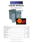
PVPV-1
Solar Battery
User’s Manual
SolarUM.2/05.Rev.0
Table of Contents
Precautions ................................................................................................... 2
Installation ..................................................................................................... 3
Adding Water................................................................................................. 5
Hydrometer.................................................................................................... 6
Voltage .......................................................................................................... 6
Specific Gravity ............................................................................................. 8
Record Keeping............................................................................................. 8
Equalize Charge............................................................................................ 9
Sulfated Batteries .......................................................................................... 9
Battery Characteristics ................................................................................ 11
Diagrams ..................................................................................................... 12
Figures ........................................................................................................ 13
Troubleshooting........................................................................................... 14
Specifications .............................................................................................. 15
Maintenance................................................................................................ 16
Records ....................................................................................................... 17
PRECAUTIONS
2
NEVER smoke or produce a spark in the battery area.
When performing battery maintenance wear safety glasses, rubber gloves and
protective clothing.
When using a hydrometer avoid letting the rubber tube shake as this can cause
drops of electrolyte to splash onto your clothing or into your eyes. Store your
hydrometer in a clean dry place.
DO NOT OVERFILL Excessive water may spill out while battery is charging.
USE ONLY DISTILLED WATER! Using tap or well water will void your warranty.
DO NOT let foreign objects enter the cells.
INSTALLATION
STEP 1
Acquire the following safety items:
Safety glasses or face shield
Acid resistant apron
Insulated 7/16 wrench
Insulated ratchet with 7/16 socket
1 gal. neutralizing agent (1# baking soda to gal. water,
mix this solution thoroughly)
Rubber gloves
NOTE:
Wrapping your tools with several layers of electrical tape will reduce the
hazard of shorting from cell to cell. You should also remove any jewelry
that may be at risk of shorting.
INSTALLATION – Continued
3
STEP 2
Inspect the battery and tray for evidence of damage, if damage has
occurred file a claim with the carrier immediately. If you see liquid on the
top of the cells pour some neutralizing agent into a small container and
apply with a clean paint brush. Be extra careful not to get any of this
agent into the cell. Apply this agent to the terminals as well as the cell
tops then rinse with clear water and wipe dry.
CAUTION:
If you should get battery acid in your eyes, flush with clear water for 15
minutes and seek medical attention. DO NOT use the neutralizing agent
in your eyes.
STEP 3
Remove the tray lid by tapping one hinge back into the lid hinge; or
remove the internal hex-head bolts.
STEP 4
Remove the buss bars.
STEP 5
Connect the cell lifting strap into the holes of the terminals and lift the
cells out of the tray. If the clevis on the cell lifting strap will not slide over
the terminal slightly spread the clevis.
NOTE:
If you move the battery fully assembled skip the remaining steps.
WARNING:
Do not let the lid fall onto the cells as this could cause shorting from
terminal to terminal.
CAUTION:
These cells can be extremely heavy, a come-along or block and tackle
may be needed to do the lifting. Do not try lifting these cells by yourself.
Serious injury could occur.
INSTALLATION – Continued
4
WARNING:
The weight inside the plastic cells will cause the sides to bulge when
removed from the tray. This is normal, however, use caution when
handling the cells. Any pressure on the sides will cause the cells to
“breathe” and can release small droplets of electrolyte in the area of the
cap. Placing a rag over the vent cap will reduce this hazard.
NOTE:
As you remove the cells from the tray you may notice the electrolyte
level is very low. DO NOT add water to the cells, this condition is
normal. As soon as the battery is reassembled, charge the battery at 2%
of its rated capacity. After approximately 2 hours, the electrolyte level
will return to normal. If the electrolyte level does not rise as expected,
contact your dealer.
STEP 6
Neutralize the sides of the cells and the steel tray. Rinse and dry
thoroughly.
STEP 7
Move the steel tray to the desired location.
STEP 8
Install the cells back into the tray using the diagram on page 12 to
ensure the cells are correctly installed. The cells must be completely
seated in the tray to properly install the cell interconnects. All plastic
spacers MUST be reinstalled when the battery is assembled.
STEP 9
Referring to the diagrams on page 12 or 13, install the nuts and bolts in
the exact pattern as shown. If your installation requires the inverter
connections to be on the opposite side of what is shown, turn the book
over and proceed. Torque all bolts to 115-135 inch lbs.
WARNING:
Never allow tools or other conductive objects to make contact with
two or more battery terminals.
INSTALLATION – Continued
STEP 10
5
Install the lid by taping the hinge pin back into the can hole. When you
install the lid you have a choice of where the hinges are located. Some
lid hinges use an internal hex head bolt, use an Allen wrench to remove
and replace the lid.
ADDING WATER
Fill to ¼” from the bottom of the cap (throat). A flashlight will make adding water
much easier. A certain amount of water loss is normal in all batteries, and must be
replaced at regular intervals with distilled or deionized water. Over filling is one of
the most common errors made during battery maintenance and will cause gradual
lowering of the specific gravity and a subsequent loss of capacity, corrosion to the
can and intercell connectors. Add water after the battery is done charging and
after taking hydrometer readings. If the battery is subjected to freezing
temperatures it is a good idea to add water when the battery is reaching
approximately ¾ charged or 1 hour before ending an equalize charge. It can take
up to several days for the fresh water to mix with the rest of the acid. This fresh
water could freeze before mixing with the electrolyte.
WARNING:
Do NOT over fill. Do NOT use tap or well water. They can contain
small amounts or nickel, iron, manganese, copper, chlorine, nitrates, etc.
These and other minerals can seriously affect battery life.
HYDROMETER
6
Insert the rubber tip into the cell but not into the electrolyte. Squeeze the bulb and
lower the rubber tip into the electrolyte and release the pressure from the bulb. The
barrel will fill up and the float will rise. It is very important for the float to be freely
suspended in the electrolyte. Gently move the hydrometer back and forth until the float
is not in contact with the barrel, where the numbers on the float intersect with the top of
the electrolyte, this is the specific gravity. See the following section for interpreting your
hydrometer readings. With the rubber tip in the cell, but not submersed into the
electrolyte, squeeze the bulb and drain the electrolyte back into the cell. Wipe dry any
spilled electrolyte.
WARNING:
Always wear protective clothing and eye/face protection when working
around batteries. If you should get acid in your eyes or on your skin,
flush with clear water for 15 minutes and see a physician. Do not use
neutralizing agent in your eyes.
VOLTAGE
OPEN CIRCUIT READINGS There is a definite relationship between the cell
voltage and the specific gravity of a cell that is on open circuit (no charging or
discharging). These open circuit voltage readings are useful in determining
uniformity. A fully charged battery on open circuit, with a specific gravity of 1.260
– 1.280 will read 2.10 volts per cell to 2.12 volts per cell at 77˚ F. This spread of
.02 vpc is considered normal for a new battery. As the battery ages, the spread will
increase to about .03 vpc.
DOD (Depth of Discharge)
0%
50%
80%
100%
NOTE:
(Full Charged)
(Half Discharged)
(Considered Dead)
(Over Discharged)
Total Battery Volts
12 v / 24 v / 48 v
12.78 / 25.56 / 51.12
12 / 24 / 48
10.5 / 21 / 42
9.3 / 18.6 / 37.2
Specific Gravity
1.275 – 1.285
1.205
1.175
1.140
You must take the electrolyte temperature into consideration when using
voltage readings (see Pg. 13).
VOLTAGE – Continued
7
FULLY CHARGED VOLTAGE READINGS On-charge voltage readings are most
informative and are good indicators of battery condition. These readings should be
taken when the battery is approaching full charge with 2% of the battery capacity
flowing into the battery. New batteries, when fully charged and 2% of the battery
capacity flowing into the battery, will have cell voltages between 2.55 – 2.65 vpc.
Older batteries with the same circumstances will have voltages about 2.45 – 2.55 vpc.
Multiplying the battery capacity times .02 will give you 2% of capacity.
Example: 6-85F-17S 845 x .02 = 16.9 amps.
VARIATIONS IN ON-CHARGE VOLTAGE If all cells of a battery show similar fullcharge voltages, they are equally healthy. The uniformity and value of the individual
cell voltage readings vary with the overall condition of the battery. A battery with an oncharge voltage of 2.45 to 2.50 volts per cell has more uniformly healthy cells than a
battery having an on-charge voltage spread of 2.40 to 2.50 volts per cell. The battery’s
age and service duty must be considered in the interpretation of the on-charge voltage
readings. An example would be an older battery which has on-charge cell voltage
readings of 2.45 volts to 2.65 volts. The reason may very well be that the inside cells
operate at higher than average temperatures causing higher local action, which would
result in lower voltage. Regular equalize charging will compensate for the higher selfloss of the inside cell. Any wide spread in on-charge voltage that could not be
attributed to the battery’s service life or age is a sign that something is wrong and
attention is necessary. Some cause of abnormally wide spread or charge voltages are:
1.
2.
3.
4.
5.
Abnormal temperature differential
Internal shorts
Acid loss causing over-discharge
Insufficient charging
Insufficient equalize charging
General Settings for Trace Inverter/Charger
Bulk
Equalize
Float
12 Volt
14.8
15 – 15.5
13.5
24 Volt
29.6
30 – 31
27
48 Volt
59.2
60 – 62
54
These voltage settings are ball park settings that will work for most systems. If you find your specific
gravity is not reaching 1.275-1.285 raise these settings by .1 volt increments until the specific gravity
readings indicate a fully charged battery. If the battery uses an excessive amount of water or is
overheating, lower the settings by .1 volt increments until the overcharge is removed.
SPECIFIC GRAVITY
8
The standard fully charged specific gravity for the HAWKER PV-1 Solar Battery is
1.275 – 1.285 at 77˚ F (see Fig. 4 and Fig. 5 on page 14) and the 100% discharged
gravity is 1.140. Since the acid content of the electrolyte decreases linearly as the cell
is discharged, the decrease in gravity is directly proportionate to the amount in
ampere-hrs taken out. The specific gravity at any point in the discharge indicates the
depth of discharge, and can be translated into ampere-hrs taken out. Knowing that the
fully charged gravity is 1.280 and the final specific gravity is 1.140 we can find our state
of discharge.
EXAMPLE: Assume the specific gravity is 1.180 that is 100 points below the
fully charged specific gravity of 1.280. With a difference of 140 points from 100%
charged to 100% discharged we can divide 100/140 = 71% discharged. Use this
formula to help keep your Amp/Hr meter synchronized with your battery. (See Fig
1 on Page 14)
WARNING:
All lead-acid batteries are considered discharged when 80% of the
capacity has been removed. NEVER remove more than 80% of the
battery capacity.
RECORD KEEPING
This simple task is required for your warranty and will be of great assistance in
determining the health of your battery. Record keeping is the single most
important tool in good battery maintenance. As the battery ages you can see
trends, spot possible problems before they become permanent and make any
adjustments to your charging systems. Without records it is almost impossible to
know how your system is functioning. While instrumentation in Renewable Energy
has made leaps and bounds, they are only another tool in the proper operation of
your battery. By using the records and instrumentation together, your battery
system can provide you with years of trouble-free service.
EQUALIZE CHARGE
9
The term “equalize” simply means a controlled overcharge. This procedure is used
to adjust the difference between cells that develop due to temperature variations
within the battery, manufacturing, and cycling of the battery. The equalize charge
will also help scrub off sulfate particles that tend to build up on the battery’s
positive plate. When to equalize: If a cell has a .020 difference in specific gravity or
at least once a month. How to equalize: Generally you continue the bulk charge for
an additional 3 hours after the battery has become full. The equalize charge rate
should be approximately 2% of the battery capacity. This will tend to raise the
battery voltage 1-1.5 volts above the bulk setting. Ensure that any sensitive loads
can accept this higher voltage.
SULFATED BATTERIES
All lead acid batteries sulfate when discharged. The active material must convert to
lead sulfate in order for the cells to produce energy. The term sulfated battery
means that the battery has developed abnormal sulfate and has its capacity
reduced as a result. The most common cause of sulfation are:
1.
2.
3.
4.
5.
6.
Under charging or neglect of equalize charge
Standing in a partially or completed discharged condition
Low electrolyte level
Adding acid
High specific gravity
High temperature
WARNING:
Do not let your battery stand in a discharged state for more than 24
hours or when temperatures are below freezing.
SULFATED BATTERIES – Continued
10
Cells of a sulfated battery give a low specific gravity and voltage reading and the
battery will not become fully charged after a regular equalize charge. Before assuming
that the battery is sulfated, rule out the possibility that low specific gravity may be due
to acid loss. If the sulfation has not progressed too far, it may be possible to return the
battery to a serviceable condition by paying careful attention to the following:
1. Neutralize, wash and dry the battery.
2. Add water to the proper level
3. Charge the battery at 2% of its capacity using the 6 hr. rate until 100% of the
battery’s capacity has been restored.
Example: 6-85F-23S
1160 A/H x .77 = 893 A/H at the 6 hr. rate
893 A/H x .02% = 17.86 amps
17.86 amps x 50 hrs = 100% of the 6 hr. capacity
4. Discharge the battery to 1.75 volts per cell (10.5 for 12 volt systems or 21 volts
for 24 volt systems) making sure not to allow any cells to go into reversal. Cell
reversal can be identified by very high cell voltage (3-4 volts) while on charge, or
very low cell voltage (1 volt or less) while being discharged.
5. Recharge until the specific gravity is the same for 3 hours.
6. Repeat the process until the specific gravity remains constant. If the battery gives
80% or more you have succeeded; if not, replace the battery.
BATTERY CHARACTERISTICS
11
DIAGRAMS
12
FIGURES
13
Freezing Points of
Battery Electrolyte
Specific
Centigrade Fahrenheit
Gravity
1.000
0
+32
1.050
-3.3
+25
1.100
-7.7
+18
1.125
-10
+14
1.150
-15
+5
1.175
-20
-4
1.200
-26
-15
1.210
-31
-23
1.220
-36
-33
1.230
-41
-42
1.260
-57
-71
1.270
-62
-80
1.280
-66
-87
1.290
-69
-92
Specific Gravity vs.
Percent Discharged
Specific Gravity @ 77˚ F
1.280
1.260
1.240
1.220
1.200
1.180
1.160
1.140
1.120
0
10
20 30 40
50 60 70
80 90 100
% Discharged
Cell Voltage Correction Factors
Electrolyte
Temperature
˚F
49-51
52-54
55-57
58-60
61-63
64-66
67-69
70-72
73-75
Cell Voltage
Correction To
Be Subtracted From
Measured Volts
-0.09
-0.08
-0.07
-0.06
-0.05
-0.04
-0.03
-0.02
-0.01
Temperature Effect
On Batteries
Electrolyte
Temperature
˚F
77˚
60˚
50˚
40˚
30˚
Percent
Capacity
100%
95%
91%
87%
81%
Electrolyte
Temperature
˚F
76-78
79-81
82-84
85-87
88-90
91-93
94-96
97-99
100-102
Cell Voltage
Correction
To Be Added
To Measured Volts
None Needed
+0.01
+0.02
+0.03
+0.04
+0.05
+0.06
+0.07
+0.08
Cell Specific
Gravity
Temperature
Correction
Temp.
Correction
Fahrenheit
Factor
39-41
-.012
42-44
-.011
45-47
-.010
48-50
-.009
51-53
-.008
54-56
-.007
57-60
-.006
61-63
-.005
64-66
-.004
67-69
-.003
70-72
-.002
73-75
-.001
76-78
0
79-81
+.001
82-84
+.002
85-87
+.003
88-91
+.004
92-94
+.005
TROUBLESHOOTING
PROBLEM
14
PROBABLE CAUSE
REMEDY
Battery not
performing as
expected.
1.
2.
3.
4.
5.
6.
Battery is undersized
Battery not fully charged
Weak or defective cells
Grounds or shorts
Phantom loads in system
Battery is spent
1.
2.
3.
4.
Replace with a larger battery
Check charger and controller
Perform a load test
Clean battery and all connections in
the system
5. Find and eliminate loads
6. Replace battery
Battery
overheats on
charge.
1.
2.
3.
4.
5.
6.
7.
8.
Improper equipment settings
Malfunction of charging equipment
Battery too deeply discharged
High resistance connection
Low electrolyte level
Battery room too warm
Weak or defective cells
Battery is spent
1.
2.
3.
4.
5.
Battery
overheats on
discharge
1.
2.
3.
4.
Excessive load
Battery not full recharged
Battery over discharged
Battery room too warm
1.
2.
3.
4.
Low
electrolyte
level
1.
2.
3.
4.
Lack of watering
Frequent overcharging
Spilled electrolyte
Cracked or broken jars
1. More care required
2. Adjust/check charging system
3. Add water, equalize and adjust
specific gravity (contact dealer)
4. Replace jars
Unequal cell
voltages
1. Overdischarging
2. Acid loss due to over-watering or
spillage
3. Corroded or dirty tops
4. Grounds in battery
5. Impurities in electrolyte
6. Battery used infrequently
7. Weak or defective cells
8. Lack of equalize charges
1. Give equalize charge
2. Give equalize charge and adjust
specific gravity
3. Neutralize and clean tops
4. Clean battery
5. Use only distilled water
6. Deep discharge and equalize
7. Repair or replace battery
8. Equalize more often
Unequal
Specific
Gravity
1. All of the above
2. Recently added water
3. Improper gravity adjustment after cell
replacement
1. All of the above
2. Gassing will mix new water
3. Adjust specific gravity(see your
dealer)
Adjust charging equipment
Verify charging equipment output
Limit discharge to 80% DOD
Check for hot connections
Water battery to correct level and
allow to cool and recharge
6. Provide cooler battery room
7. Repair or replace battery
8. Replace battery
Reduce loads. Need larger battery
Let battery cool. Do a load test
Limit discharge to 80% DOD
Provide cooler battery room
TROUBLESHOOTING
15
Dimensions
LxWxH in
Inches @ 12 V
38.25 x 6.94 x 25
Weight in
Lbs.*
6-85F-17S
Rated
Amp Hrs @
20 hr. Rate
845
666
Short Circuit
Ratings Amps
@ 104˚ F
9,600
6-85F-19S
950
38.25 x 7.69 x 25
738
10,800
6-85F-21S
1055
38.25 x 8.44 x 25
816
12,000
6-85F-23S
1160
38.25 x 9.19 x 25
888
13,300
6-85F-25S
1270
38.25 x 9.94 x 25
966
14,400
6-85F-27S
1375
38.25 x 10.69 x 25
1044
15,600
6-85F-29S
1482
38.25 x 11.44 x 25
1116
16,800
6-85F-31S
1585
38.25 x 12.19 x 25
1194
18,000
6-85F-33S
1690
38.25 X 12.94 x 25
1272
19,200
Model #
(12 Volt)
*Weights +/-5%
Warranty
Cycles to 80% DOD
Battery Type
Positive Plate
Post-to-Cover Seal
Cell “Jar” Material
Cell Cover Material
Tray Material
Intercell Connectors
Specific Gravity @ 77˚ F
Model # Breakdown
Example:
10 years
2100 over 10 years
Flooded Lead-Acid
Tetrafluoroethylene (Teflon®)/Lead Antimony)
Burned Post to Cover
Injection Molded Polypropylene
Polypropylene
Epoxy Coated Steel
Lead Plated Copper Rated @ 700 Amps
1.285-1.275 Fully Charged 1.160 80% Discharged
6-85F-17S
6 cells per Tray
85 amps per positive plate
F represents Powerline
17 plates total (8 pos. & 9 neg)
PV-1 Solar Battery
Photo is a 12-85F-13 battery.
MAINTENANCE
16
WEEKLY
1. Record hydrometer reading of pilot cell (the cell with the lowest specific gravity
when you first received the battery). Once a year select a different cell to be the
pilot cell.
2. Check the water level (add as needed).
3. Record Amp/Hrs consumed.
4. Inspect connections for corrosion (clean as needed).
MONTHLY
1. Record hydrometer readings of all cells (after the battery is fully charged).
2. Check water level (add as needed).
a. If the average readings are less than 1.275 – 1.285 check all charging
sources and adjust as needed.
b. If one or two cells read 20 points more or less than the average, circle
those readings and check for improvement at next monthly reading. If the
low cells do not improve, the cells are in need of an equalize charge,
specific gravity adjustment or internal inspection.
3. Record Amp/Hrs consumed.
4. Record battery temperature.
5. Clean battery with a damp cloth. (If battery tops are wet with acid use neutralizing
agent with a clean paint brush, dry thoroughly.)
6. Equalize the battery (see Page 5).
7. Inspect connections for corrosion (clean as needed).
YEARLY
1. Torque all terminal bolts.
RECORDS
17
ENTERING DATA IN THE WEEKLY FORMS
It is essential that you label each cell for these records to aid in the operation of your battery. This
form is designed to enter general battery information on a weekly basis and will, at a glance, show
any abnormalities in the battery’s health.
Select a pilot cell, this should be the cell with the lowest specific gravity after you do your initial
charge after installation. It is suggested that the pilot be rotated annually to a different cell in the
battery.
Step 1.
Step 2.
Step 3.
Step 4.
Step 5.
Step 6.
Enter the date.
Enter the pilot cells voltage.
Enter the specific gravity of the pilot cell.
Check your A/H meter and enter the amp/hrs reading.
Enter the cell temperature.
Enter a “W” if water has been added in the previous week. Enter an “E” if the
battery has been equalized in the previous week. Enter a “C” if the battery was
cleaned in the previous week.
ENTERING DATA IN THE MONTHLY FORMS
Once a month enter the specific gravity and cell volt ages of all cells in the appropriate columns. If
your battery has more than 12 cells you can identify these cells as “AA, BB, CC” , etc.
WEEKLY
DATE
CELL
VOLTAGE
SP. GR.
A/H USED
CELL TEMP.
W.E.C.
WEEKLY
DATE
CELL
VOLTAGE
SP. GR.
A/H USED
CELL TEMP.
W.E.C.
WEEKLY
DATE
CELL
VOLTAGE
SP. GR.
A/H USED
CELL TEMP.
W.E.C.
WEEKLY
DATE
CELL
VOLTAGE
SP. GR.
A/H USED
CELL TEMP.
W.E.C.
WEEKLY
DATE
CELL
VOLTAGE
SP. GR.
A/H USED
CELL TEMP.
W.E.C.
WEEKLY
DATE
CELL
VOLTAGE
SP. GR.
A/H USED
CELL TEMP.
W.E.C.
WEEKLY
DATE
CELL
VOLTAGE
SP. GR.
A/H USED
CELL TEMP.
W.E.C.
WEEKLY
DATE
CELL
VOLTAGE
SP. GR.
A/H USED
CELL TEMP.
W.E.C.
WEEKLY
DATE
CELL
VOLTAGE
SP. GR.
A/H USED
CELL TEMP.
W.E.C.
WEEKLY
DATE
CELL
VOLTAGE
SP. GR.
A/H USED
CELL TEMP.
W.E.C.
WEEKLY
DATE
CELL
VOLTAGE
SP. GR.
A/H USED
CELL TEMP.
W.E.C.
MONTHLY
CELL
SP. GR.
Cell Voltage
CELL
A
A
B
B
C
C
D
D
E
E
F
F
G
G
H
H
I
I
K
K
K
K
L
L
CELL
SP. GR.
Cell Voltage
CELL
A
A
B
B
C
C
D
D
E
E
F
F
G
G
H
H
I
I
K
K
K
K
L
L
SP. GR.
Cell Voltage
SP. GR.
Cell Voltage
MONTHLY
CELL
SP. GR.
Cell Voltage
CELL
A
A
B
B
C
C
D
D
E
E
F
F
G
G
H
H
I
I
K
K
K
K
L
L
CELL
SP. GR.
Cell Voltage
CELL
A
A
B
B
C
C
D
D
E
E
F
F
G
G
H
H
I
I
K
K
K
K
L
L
SP. GR.
Cell Voltage
SP. GR.
Cell Voltage
MONTHLY
CELL
SP. GR.
Cell Voltage
CELL
A
A
B
B
C
C
D
D
E
E
F
F
G
G
H
H
I
I
K
K
K
K
L
L
CELL
SP. GR.
Cell Voltage
CELL
A
A
B
B
C
C
D
D
E
E
F
F
G
G
H
H
I
I
K
K
K
K
L
L
SP. GR.
Cell Voltage
SP. GR.
Cell Voltage
MONTHLY
CELL
SP. GR.
Cell Voltage
CELL
A
A
B
B
C
C
D
D
E
E
F
F
G
G
H
H
I
I
K
K
K
K
L
L
CELL
SP. GR.
Cell Voltage
CELL
A
A
B
B
C
C
D
D
E
E
F
F
G
G
H
H
I
I
K
K
K
K
L
L
SP. GR.
Cell Voltage
SP. GR.
Cell Voltage
MONTHLY
CELL
SP. GR.
Cell Voltage
CELL
A
A
B
B
C
C
D
D
E
E
F
F
G
G
H
H
I
I
K
K
K
K
L
L
CELL
SP. GR.
Cell Voltage
CELL
A
A
B
B
C
C
D
D
E
E
F
F
G
G
H
H
I
I
K
K
K
K
L
L
SP. GR.
Cell Voltage
SP. GR.
Cell Voltage
MONTHLY
CELL
SP. GR.
Cell Voltage
CELL
A
A
B
B
C
C
D
D
E
E
F
F
G
G
H
H
I
I
K
K
K
K
L
L
CELL
SP. GR.
Cell Voltage
CELL
A
A
B
B
C
C
D
D
E
E
F
F
G
G
H
H
I
I
K
K
K
K
L
L
SP. GR.
Cell Voltage
SP. GR.
Cell Voltage
MONTHLY
CELL
SP. GR.
Cell Voltage
CELL
A
A
B
B
C
C
D
D
E
E
F
F
G
G
H
H
I
I
K
K
K
K
L
L
CELL
SP. GR.
Cell Voltage
CELL
A
A
B
B
C
C
D
D
E
E
F
F
G
G
H
H
I
I
K
K
K
K
L
L
SP. GR.
Cell Voltage
SP. GR.
Cell Voltage
MONTHLY
CELL
SP. GR.
Cell Voltage
CELL
A
A
B
B
C
C
D
D
E
E
F
F
G
G
H
H
I
I
K
K
K
K
L
L
CELL
SP. GR.
Cell Voltage
CELL
A
A
B
B
C
C
D
D
E
E
F
F
G
G
H
H
I
I
K
K
K
K
L
L
SP. GR.
Cell Voltage
SP. GR.
Cell Voltage
MONTHLY
CELL
SP. GR.
Cell Voltage
CELL
A
A
B
B
C
C
D
D
E
E
F
F
G
G
H
H
I
I
K
K
K
K
L
L
CELL
SP. GR.
Cell Voltage
CELL
A
A
B
B
C
C
D
D
E
E
F
F
G
G
H
H
I
I
K
K
K
K
L
L
SP. GR.
Cell Voltage
SP. GR.
Cell Voltage
MONTHLY
CELL
SP. GR.
Cell Voltage
CELL
A
A
B
B
C
C
D
D
E
E
F
F
G
G
H
H
I
I
K
K
K
K
L
L
CELL
SP. GR.
Cell Voltage
CELL
A
A
B
B
C
C
D
D
E
E
F
F
G
G
H
H
I
I
K
K
K
K
L
L
SP. GR.
Cell Voltage
SP. GR.
Cell Voltage
MONTHLY
CELL
SP. GR.
Cell Voltage
CELL
A
A
B
B
C
C
D
D
E
E
F
F
G
G
H
H
I
I
K
K
K
K
L
L
CELL
SP. GR.
Cell Voltage
CELL
A
A
B
B
C
C
D
D
E
E
F
F
G
G
H
H
I
I
K
K
K
K
L
L
SP. GR.
Cell Voltage
SP. GR.
Cell Voltage
MONTHLY
CELL
SP. GR.
Cell Voltage
CELL
A
A
B
B
C
C
D
D
E
E
F
F
G
G
H
H
I
I
K
K
K
K
L
L
CELL
SP. GR.
Cell Voltage
CELL
A
A
B
B
C
C
D
D
E
E
F
F
G
G
H
H
I
I
K
K
K
K
L
L
SP. GR.
Cell Voltage
SP. GR.
Cell Voltage