1
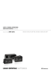
Safety, Storage, Operating and
Maintenance Manual
VRLA Battery Systems
mSeries, DDm, DDS, DGX, DDV
and SC
Publication No. US-VR-OM-002 March 2008
Safety, Storage, Operating and
Maintenance Manual
VRLA Battery Systems
mSeries, DDm, DDS, DGX, DDV
and SC
When working with any EnerSys® Modular Battery System, be
sure to refer to the Installation Manual specified for that system
and Rack Assembly Instructions included in the rack shipment.
Publication No. US-VR-OM-002 March 2008
This manual provides full instructions regarding safety, storage, operation, and maintenance for
EnerSys® valve-regulated lead acid batteries, as well as certain installation considerations. To
maximize safety and performance, read the accompanying Installation Manual thoroughly.
Failure to observe the precautions as presented may result in injury or loss of life.
© 2008 by EnerSys. All rights reserved.
This document is proprietary to EnerSys. This document cannot be copied or reproduced in
whole or in part, without the express written permission of EnerSys.
Please check our website for literature updates.
www.enersys.com
www.enersys.com
Publication No. US-VR-OM-002
March 2008
GENERAL SAFETY INSTRUCTIONS
Warnings in this manual appear in any of three ways:
Danger
The danger symbol is a lightning bolt mark enclosed in
a triangle. The danger symbol is used to indicate
imminently hazardous situations, locations and
conditions which, if not avoided, WILL result in death,
serious injury and/or severe property damage.
Warning
The warning symbol is an exclamation mark in a
triangle. The warning symbol is used to indicate
potentially hazardous situations and conditions, which
if not avoided COULD result in serious injury or death.
Severe property damage COULD also occur.
Caution
The caution symbol is an exclamation mark enclosed
in a triangle. The caution symbol is used to indicate
potentially hazardous situations and conditions, which
if not avoided may result in injury. Equipment damage
may also occur.
Other warning symbols may appear along with the Danger and Caution symbol and are used to
specify special hazards. These warnings describe particular areas where special care and/or
procedures are required in order to prevent serious injury and possible death:
Electrical
warnings
The electrical warning symbol is a lightning bolt mark
enclosed in a triangle. The electrical warning symbol is
used to indicate high voltage locations and conditions,
which may cause serious injury or death if the proper
precautions are not observed.
Explosion
warnings
The explosion warning symbol is an explosion mark
enclosed in a triangle. The explosion warning symbol is
used to indicate locations and conditions where
molten, exploding parts may cause serious injury or
death if the proper precautions are not observed.
Publication No. US-VR-OM-002
March 2008
i
www.enersys.com
IMPORTANT SAFETY INSTRUCTIONS
DANGER
A battery can present a risk of electrical shock and high short circuit current.
The following precautions should be observed when working with batteries.
1. Verify that the Uninterruptible Power Supply (UPS) is off and that power cord is
disconnected from the power source.
2. Remove watches, rings or other metal objects.
3. Use tools with insulated handles to prevent inadvertant shorts.
4. Wear rubber gloves and boots.
5. Do not lay tools or metal parts on top of batteries.
6. Determine if the battery is inadvertently grounded. If inadvertently grounded, remove
source of ground. Contact with any part of a grounded battery can result in electrical
shock. The likelihood of such shock will be reduced if such grounds are removed
during installation and maintenance.
7. Verify circuit polarities before making connections.
8. Disconnect charging source and load before connecting or disconnecting terminals.
9. Valve-regulated lead-acid (VRLA) batteries contain an explosive mixture of hydrogen
gas. Do not smoke, cause a flame or spark in the immediate area of the batteries. This
includes static electricity from the body.
10. Use proper lifting means when moving batteries and wear all appropriate safety clothing
and equipment.
11. Do not dispose of lead acid batteries except through channels in accordance with local,
state and federal regulations.
ii
www.enersys.com
Publication No. US-VR-OM-002
March 2008
IMPORTANT SAFETY INSTRUCTIONS
SAVE THESE INSTRUCTIONS
This manual contains important instructions for PowerSafe™ mSeries Lead-Acid Battery Systems
that should be followed during the installation and maintenance of the battery system.
Only a qualified EnerSys® service representative who is knowledgeable in batteries and
the required precautions should perform servicing of the batteries. Keep unauthorized
personnel away from batteries.
CAUTION
Misuse of this equipment could result in human injury and
equipment damage. In no event will EnerSys be responsible or
liable for either indirect or consequential damage or injury that may
result from the use of this equipment.
Do not dispose of the batteries in a fire. The batteries may
CAUTION explode.
Do not open or mutilate the batteries. Released electrolyte is
CAUTION harmful to the eyes and skin and may also be toxic.
This unit contains sealed lead acid batteries. Lack of preventative
WARNING maintenance could result in batteries exploding and emitting
gasses and/or flame. An authorized, trained technician must
perform annual preventative maintenance.
Failure to replace a battery before it becomes exhausted may
cause the case to crack, possibly releasing electrolyte from inside
WARNING the battery and resulting in secondary faults such as odor, smoke
and fire.
Installation and servicing of batteries should be performed by
WARNING personnel knowledgeable about batteries and the required
precautions. Keep unauthorized personnel away from the
batteries.
Proper maintenace to the battery system of this unit must be done
WARNING by a qualified service technician. This is essential to the safety and
reliability of your Uninterruptible Power Supply (UPS) system.
Publication No. US-VR-OM-002
March 2008
iii
www.enersys.com
When working with any EnerSys® Modular Battery System, be
sure to refer to the Installation Manual specified for that system
and Rack Assembly Instructions included in the rack shipment.
iv
www.enersys.com
Publication No. US-VR-OM-002
March 2008
TABLE OF CONTENTS
GENERAL SAFETY INSTRUCTIONS . . . . . . . . . . . . . . . . . . . . . . . . . . . . . . . . . . . . . . . . . . . . . . . . . . . . i
1.0
GENERAL INFORMATION . . . . . . . . . . . . . . . . . . . . . . . . . . . . . . . . . . . . . . . . . . . . . . . . . . . . . . . 1
1.1 Introduction . . . . . . . . . . . . . . . . . . . . . . . . . . . . . . . . . . . . . . . . . . . . . . . . . . . . . . . . . . . . . . . . . 1
1.2 Precautions . . . . . . . . . . . . . . . . . . . . . . . . . . . . . . . . . . . . . . . . . . . . . . . . . . . . . . . . . . . . . . . . . 1
1.3 Service. . . . . . . . . . . . . . . . . . . . . . . . . . . . . . . . . . . . . . . . . . . . . . . . . . . . . . . . . . . . . . . . . . . . . 2
2.0
SAFETY . . . . . . . . . . . . . . . . . . . . . . . . . . . . . . . . . . . . . . . . . . . . . . . . . . . . . . . . . . . . . . . . . . . . . . 3
2.1 General . . . . . . . . . . . . . . . . . . . . . . . . . . . . . . . . . . . . . . . . . . . . . . . . . . . . . . . . . . . . . . . . . . . . 3
2.2 Safety Equipment and Clothing . . . . . . . . . . . . . . . . . . . . . . . . . . . . . . . . . . . . . . . . . . . . . . . . . 3
2.3 Safety Precautions . . . . . . . . . . . . . . . . . . . . . . . . . . . . . . . . . . . . . . . . . . . . . . . . . . . . . . . . . . . 4
2.3.1 Sulfuric Acid Burns . . . . . . . . . . . . . . . . . . . . . . . . . . . . . . . . . . . . . . . . . . . . . . . . . . . . . . 4
2.3.2 Explosive Gases. . . . . . . . . . . . . . . . . . . . . . . . . . . . . . . . . . . . . . . . . . . . . . . . . . . . . . . . . 5
2.3.3 Electrical Shocks and Burns . . . . . . . . . . . . . . . . . . . . . . . . . . . . . . . . . . . . . . . . . . . . . . . 5
3.0
INSPECTING THE BATTERY SHIPMENT . . . . . . . . . . . . . . . . . . . . . . . . . . . . . . . . . . . . . . . . . . . 7
3.1 General . . . . . . . . . . . . . . . . . . . . . . . . . . . . . . . . . . . . . . . . . . . . . . . . . . . . . . . . . . . . . . . . . . . . 7
3.2 Visible External Damage . . . . . . . . . . . . . . . . . . . . . . . . . . . . . . . . . . . . . . . . . . . . . . . . . . . . . . . 7
3.3 Concealed Damage. . . . . . . . . . . . . . . . . . . . . . . . . . . . . . . . . . . . . . . . . . . . . . . . . . . . . . . . . . . 8
4.0
BATTERY STORAGE BEFORE INSTALLATION . . . . . . . . . . . . . . . . . . . . . . . . . . . . . . . . . . . . . . 9
4.1 General . . . . . . . . . . . . . . . . . . . . . . . . . . . . . . . . . . . . . . . . . . . . . . . . . . . . . . . . . . . . . . . . . . . . 9
4.2 Storage Location . . . . . . . . . . . . . . . . . . . . . . . . . . . . . . . . . . . . . . . . . . . . . . . . . . . . . . . . . . . . . 9
4.3 Advance Preparation . . . . . . . . . . . . . . . . . . . . . . . . . . . . . . . . . . . . . . . . . . . . . . . . . . . . . . . . . 10
5.0
INSTALLATION CONSIDERATIONS . . . . . . . . . . . . . . . . . . . . . . . . . . . . . . . . . . . . . . . . . . . . . . . 11
5.1 General . . . . . . . . . . . . . . . . . . . . . . . . . . . . . . . . . . . . . . . . . . . . . . . . . . . . . . . . . . . . . . . . . . . 11
5.2 Considerations for Connecting the Battery System to Operating Equipment . . . . . . . . . . . . . 12
5.3 Considerations for Parallel Installation . . . . . . . . . . . . . . . . . . . . . . . . . . . . . . . . . . . . . . . . . . . 13
6.0
UNPACKING AND HANDLING FOR INSTALLATION . . . . . . . . . . . . . . . . . . . . . . . . . . . . . . . . . 14
6.1 General . . . . . . . . . . . . . . . . . . . . . . . . . . . . . . . . . . . . . . . . . . . . . . . . . . . . . . . . . . . . . . . . . . . 14
6.2 Accessories . . . . . . . . . . . . . . . . . . . . . . . . . . . . . . . . . . . . . . . . . . . . . . . . . . . . . . . . . . . . . . . . 14
6.3 Recommended Installation Equipment and Supplies . . . . . . . . . . . . . . . . . . . . . . . . . . . . . . . . 15
7.0
INITIAL and/or FRESHENING CHARGE. . . . . . . . . . . . . . . . . . . . . . . . . . . . . . . . . . . . . . . . . . . . 16
8.0
OPERATION . . . . . . . . . . . . . . . . . . . . . . . . . . . . . . . . . . . . . . . . . . . . . . . . . . . . . . . . . . . . . . . . . . 17
8.1 General . . . . . . . . . . . . . . . . . . . . . . . . . . . . . . . . . . . . . . . . . . . . . . . . . . . . . . . . . . . . . . . . . . . 17
8.1.1 Determining the State-of-Charge. . . . . . . . . . . . . . . . . . . . . . . . . . . . . . . . . . . . . . . . . . . 17
8.2 Float Operation . . . . . . . . . . . . . . . . . . . . . . . . . . . . . . . . . . . . . . . . . . . . . . . . . . . . . . . . . . . . . 18
8.2.1 Float Charge Method . . . . . . . . . . . . . . . . . . . . . . . . . . . . . . . . . . . . . . . . . . . . . . . . . . . . 19
8.3 Equalizing Charge . . . . . . . . . . . . . . . . . . . . . . . . . . . . . . . . . . . . . . . . . . . . . . . . . . . . . . . . . . . 20
8.3.1 Equalizing Charge Method. . . . . . . . . . . . . . . . . . . . . . . . . . . . . . . . . . . . . . . . . . . . . . . . 21
Publication No. US-VR-OM-002
March 2008
v
www.enersys.com
9.0
BATTERY TAPS . . . . . . . . . . . . . . . . . . . . . . . . . . . . . . . . . . . . . . . . . . . . . . . . . . . . . . . . . . . . . . . 22
10.0 PILOT CELL . . . . . . . . . . . . . . . . . . . . . . . . . . . . . . . . . . . . . . . . . . . . . . . . . . . . . . . . . . . . . . . . . . 22
11.0 MAINTENANCE . . . . . . . . . . . . . . . . . . . . . . . . . . . . . . . . . . . . . . . . . . . . . . . . . . . . . . . . . . . . . . . 22
11.1 Battery Cleaning . . . . . . . . . . . . . . . . . . . . . . . . . . . . . . . . . . . . . . . . . . . . . . . . . . . . . . . . . . . 22
11.1.1 Standard Cleaning . . . . . . . . . . . . . . . . . . . . . . . . . . . . . . . . . . . . . . . . . . . . . . . . . . . . . 22
11.1.2 Corrosion Cleaning. . . . . . . . . . . . . . . . . . . . . . . . . . . . . . . . . . . . . . . . . . . . . . . . . . . . . 23
11.1.3 Heavy Corrosion Cleaning . . . . . . . . . . . . . . . . . . . . . . . . . . . . . . . . . . . . . . . . . . . . . . . 23
11.2 Test Procedures . . . . . . . . . . . . . . . . . . . . . . . . . . . . . . . . . . . . . . . . . . . . . . . . . . . . . . . . . . . . 24
11.2.1 Procedure for Battery Capacity Tests . . . . . . . . . . . . . . . . . . . . . . . . . . . . . . . . . . . . . . 24
11.3 Maintenance Records . . . . . . . . . . . . . . . . . . . . . . . . . . . . . . . . . . . . . . . . . . . . . . . . . . . . . . . 26
12.0 TEMPORARY NON-USE (EXTENDED OUTAGE) . . . . . . . . . . . . . . . . . . . . . . . . . . . . . . . . . . . . 29
12.1 Installed/Out-of-Service-System . . . . . . . . . . . . . . . . . . . . . . . . . . . . . . . . . . . . . . . . . . . . . . . 29
12.2 Return to Service . . . . . . . . . . . . . . . . . . . . . . . . . . . . . . . . . . . . . . . . . . . . . . . . . . . . . . . . . . . 29
vi
www.enersys.com
Publication No. US-VR-OM-002
March 2008
1.0 GENERAL INFORMATION
1.1 Introduction
EnerSys® modular valve-regulated lead acid (VRLA) batteries have unique features that make
them easy to install and maintain. These batteries are composed of absorbed glass mat (AGM)
separators with flat plates and/or gelled electrolyte with tubular positive plates.
The AGM retains the acid between the plates to ensure long float service. In the case of gelled
acid, the acid is retained in a gel medium; thus, maximum contact with the plates ensures long
float service in cycling applications. Furthermore, the tubular positive plate design holds the
active material in position, providing excellent high cycling ability (1200 cycles to 80% DOD).
Both utilize gas recombinant technology to minimize maintenance.
PowerSafe™ batteries utilize calcium alloy grids (NO cadmium) which float at a lower current
than antimony (Sb). Lower float currents, in conjunction with superior and uniform thermal
management, reduce the chances of thermal runaway. (Temperature compensation chargers
are also recommended.)
PowerSafe VRLA batteries typically do not require special battery rooms because excess hydrogen is not emitted under normal operating conditions. In addition, the modules make installation
fast and easy.
1.2 Precautions
BEFORE UNPACKING, STORING, HANDLING, INSTALLING, OPERATING OR PERFORMING
MAINTENANCE ON THE ENERSYS VRLA BATTERY SYSTEM:
READ
THE FOLLOWING
INFORMATION THOROUGHLY!
It is important to read, understand and strictly follow the instructions in this manual.
If the following precautions are not fully understood, or if local conditions are not covered,
contact your nearest EnerSys sales/service representative for clarification or call the corporate
office number listed on the back of this manual and ask for EnerSys Reserve Power Service.
Also, refer to all applicable federal, state and local regulations and industry standards.
YOU SHOULD BE TRAINED IN HANDLING, INSTALLING, OPERATING AND MAINTAINING
BATTERIES BEFORE YOU WORK ON ANY BATTERY SYSTEM.
Publication No. US-VR-OM-002
March 2008
1
www.enersys.com
1.3 Service
Should you require installation supervision, service, parts, accessories or maintenance;
EnerSys® has a nationwide service organization to assist with your new battery purchase.
Please call your nearest EnerSys sales/service representative for more information or call the
corporate office number listed on the back of this manual and ask for EnerSys Reserve Power
Service.
2
www.enersys.com
Publication No. US-VR-OM-002
March 2008
2.0 SAFETY
2.1 General
PowerSafe™ valve-regulated lead acid batteries are reduced-maintenance batteries that operate on recombinant principles and are safer than conventional "wet cell" lead-acid batteries.
Under NORMAL operating conditions and use, their design features:
• minimize hydrogen gas release
• virtually eliminate acid misting
• essentially eliminate leakage
Under ABNORMAL operating conditions or as a result of damage, abuse and/or misuse, the
potentially hazardous conditions of hydrogen gassing, acid misting and leakage may occur.
YOU SHOULD BE TRAINED IN HANDLING, INSTALLING, OPERATING AND MAINTAINING
BATTERIES BEFORE YOU WORK ON ANY BATTERY SYSTEM.
You MUST understand the risk of working with batteries and BE PREPARED and
EQUIPPED to take the necessary safety precautions. If not, contact EnerSys® Reserve
Power Service.
2.1 Safety Equipment and Clothing
When working with any battery system, be sure you have the necessary tools and safety
equipment, including but not limited to:
• insulated tools
• rubber gloves
• fire extinguisher
• rubber apron
• safety goggles
• acid spill cleanup kit
• face shields
• emergency eye wash
• and shower, if available
ALWAYS:
• remove all jewelry (i.e., rings, watches, chains, etc.)
• keep sparks, flames and smoking materials away from the battery
NEVER lay tools or other metallic objects on the battery modules.
Using the correct tools and wearing proper safety equipment will help prevent injury should an
accident occur.
Publication No. US-VR-OM-002
March 2008
3
www.enersys.com
2.3 Safety Precautions
2.3.1
Sulfuric Acid Burns
Because VRLA cells are sealed, they normally do not present an acid
danger. However, they do contain sulfuric acid, which can cause burns
and other serious injuries.
Always wear protective clothing AND use the correct safety tools.
In case of SKIN CONTACT with sulfuric acid, IMMEDIATELY
1.
REMOVE contaminated CLOTHING
2.
FLUSH the area THOROUGHLY with WATER
3.
Get MEDICAL ATTENTION, if required.
In case of EYE CONTACT with sulfuric acid, IMMEDIATELY
1.
FLUSH THOROUGHLY for at least 15 minutes with large
amounts of WATER.
2.
Get MEDICAL ATTENTION.
In case of sulfuric acid CONTACT WITH CLOTHING OR MATERIAL,
IMMEDIATELY
1.
REMOVE CONTAMINATED CLOTHING
2.
Apply a solution of sodium bicarbonate solution (1.0lb/1.0gal or
0.5 kg/5.0 liters of water) on the clothing or material.
3.
Apply the solution until bubbling stops, then rinse with clean water.
NOTE:
In case of a sulfuric acid SPILL, bicarbonate of soda or an emergency spill kit should
be within the battery room in accordance with OSHA regulations 1910.178g2.
4
www.enersys.com
Publication No. US-VR-OM-002
March 2008
2.3.2 Explosive Gases
Batteries can generate gases, which when released can explode,
causing blindness and other serious personal injury.
Always wear protective clothing and use the correct safety tools.
Eliminate any potential of sparks, flames or arcing.
IN CASE OF FIRE: To extinguish a fire in a battery room containing lead-acid batteries, use a
CO2, foam or dry-chemical extinguishing medium. Do NOT discharge the extinguisher directly
onto the battery. The resulting thermal shock may cause cracking of the battery case/cover.
SPECIAL PROCEDURES:
If batteries are on charge, shut off power. Use positive-pressure, self-contained breathing
apparatus. Wear acid resistant clothing. Water applied to electrolyte generates heat and
causes it to splatter.
TOXIC FUMES:
Burning plastic may cause toxic fumes. Leave area as soon as possible if toxic fumes
are present. Wear breathing apparatus if required to remain in the area.
2.3.3 Electrical Shocks and Burns
Multi-cell battery systems can attain high voltage and/or currents. Do NOT
touch uninsulated batteries, connectors or terminals. To prevent serious
electrical burns and shock, use EXTREME CAUTION when working with
the system.
Always wear protective clothing and use nonconductive or insulated safety tools when
working with ANY battery system.
Remove all jewelry that could produce a short circuit.
BEFORE working on the system:
1.
Disconnect ALL loads and power sources to the battery. Use appropriate
lockout/tagout procedures.
2.
If working on an assembled battery system, sectionalize (interrupt the battery
sections) into safe working voltage levels.
3.
Check the battery system grounding. Grounding of the battery system is NOT
recommended. However, grounding of the rack is recommended.
Publication No. US-VR-OM-002
March 2008
5
www.enersys.com
IF BATTERY SYSTEM IS GROUNDED: (system is intentionally grounded by connecting a
battery terminal to ground)
1.
An increased shock hazard exists between the terminal of
opposite polarity and ground, (i.e., dirt and acid on top of battery
cell touching rack).
2.
If an unintentional ground develops within the already grounded
system, a short circuit may occur and cause explosion or fire.
IF BATTERY SYSTEM IS GROUNDED:
1.
If an unintentional ground develops within the system, an
increased shock hazard exists between the terminal of opposite
polarity and ground.
2.
If a second unintentional ground develops within the already
unintentionally grounded system, a short circuit may occur and
cause explosion or fire.
Therefore, should you be required to work on a grounded battery system, make absolutely
sure you use the correct safety precautions, equipment and clothing.
IMPORTANT
If you have ANY questions concerning safety when working with the battery system,
contact your nearest EnerSys® sales/service representative to clarify any of the noted
safety precautions, or call the corporate office number listed on the back of this manual
and ask for EnerSys Reserve Power Service.
6
www.enersys.com
Publication No. US-VR-OM-002
March 2008
3.0 INSPECTING THE BATTERY SHIPMENT
3.1 General
Precautions have been taken to pack the battery units, individual cells or cabinets containing
batteries for shipment to ensure their safe arrival. However, upon receipt, you should inspect
for evidence of damage that may have occurred during transit.
WARNING
During inspections, take precautions against electrical shock.
You are handling LIVE batteries.
3.2 Visable External Damage
IMMEDIATELY upon delivery (while the carrier representative is still on-site), inventory all
materials against the Bill of Lading and inspect for visible external damage.
Check material quantities received against the Bill of Lading, including the number of
battery pallets and the number of accessory boxes.
Note any:
•
damage to packing material.
•
wetness or stains, indicating electrolyte leakage.
If damage is noted:
1. Make a descriptive notation on the delivery receipt before signing.
2. Request an inspection by the carrier.
3. File a damage report.
Publication No. US-VR-OM-002
March 2008
7
www.enersys.com
3.3 Concealed Damage
Within 15 days of receipt, unpack the cells/batteries and check for concealed
damage. Remember, you are handling a LIVE battery. Take precaution against
a shock hazard. Follow all safety precautions as noted in Section 2.0.
Note any:
•
damage to packing material.
•
wetness or stains, indicating electrolyte leakage.
If damage is noted:
1. Request an inspection by the carrier.
2. File a concealed-damage claim.
Check the received materials against the detailed packing list to verify receipt of all materials
in the quantities specified.
For export, the cells may be packed in wooden boxes which must be opened completely and
carefully, and the cells then handled as described hereafter. See Section 6 for unpacking and
handling.
DELAY IN NOTIFYING THE CARRIER MAY RESULT IN LOSS OF YOUR RIGHT TO
REIMBURSEMENT FOR DAMAGES. Refer to the Bill of Lading, if, when performing the parts
inventory, you are unsure about the appearance of a part.
If you have any questions concerning potential damages, contact your nearest EnerSys®
sales/ service representative, or call the corporate office number listed on the back of this
manual and ask for EnerSys Reserve Power Service.
8
www.enersys.com
Publication No. US-VR-OM-002
March 2008
4.0 BATTERY STORAGE BEFORE INSTALLATION
4.1
General
Batteries should be unpacked, installed and charged as soon as possible after receipt.
However, if this is impractical, follow the instructions below for storing the battery before
installation.
4.2
Storage Location
1. Store batteries indoors in a clean, dry and cool location. Storage at higher
temperatures will result in accelerated rates of self-discharge and possible
deterioration of battery performance and life.
2. Do NOT stack pallets. DAMAGE MAY OCCUR AND THE WARRANTY MAY BE VOIDED.
3. The maximum storage time from shipment to initial charge is six months for batteries
stored at ambient temperatures no warmer than 77˚F (25˚C). For storage temperatures
greater than 77˚F (25˚C), the battery must be recharged one (1) month sooner for every
5˚F (3˚C) increase above 77˚F (25˚C). See Table 4.1.
TABLE 4.1
STORAGE TEMPERATURE
STORAGE TIME
32˚F (0˚C) to 50˚F (10˚C)
9 months
51˚F (11˚C) to 77˚F (25˚C)
6 months
78˚F (26˚C) to 92˚F (33˚C)
3 months
If storage time exceeds the storage time recommended in Table 4.1, give the battery a
freshening charge before the end of the recommended storage interval. See Section 7 for
charging information.
PowerSafe™ VRLA mSeries, DDm, DDS and DDV batteries must be charged in the horizontal
position. Charging in the vertical position could void the warranty.
4. Repeat the freshening charge for each additional storage interval until the battery is installed.
Storage at higher temperatures will result in accelerated rates of self-discharge and possible
deterioration of battery performance and life. Storage times exceeding the above may result
in plate sulfation, which may adversely affect electrical performance and expected life.
5. Maximum total storage time prior to installation is two (2) years from date of shipment
from the factory to the customer. Freshening charges are required before the end of the
storage time period, or more frequently, as noted in Table 4.1.
6. FAILURE TO CHARGE AS NOTED VOIDS THE BATTERY'S WARRANTY.
Publication No. US-VR-OM-002
March 2008
9
www.enersys.com
4.3 Advanced Preparation
If storage time is likely to be exceeded, make advance preparation to have an adequate
charger available and adjacent to an appropriate AC supply voltage. Positioning of the
cells to accept temporary intercell connectors is another consideration of advance
planning. Keep cells on styrofoam pads until the cells are installed on the rack
(when applicable).
Make every effort to get the battery connected to the charger before expiration of the
storage period, thereby avoiding the additional labor cost of preliminary freshening charges.
WARNING
Failure To Charge As Noted Voids The Battery’s Warranty
10
www.enersys.com
Publication No. US-VR-OM-002
March 2008
BEFORE INSTALLATION
READ THIS SECTION THOROUGHLY.
5.0 INSTALLATION CONSIDERATIONS
5.1 General
If you have any questions concerning the installation considerations, contact your EnerSys®
sales/service representative for clarification or call the corporate office number listed on the
back of this manual and ask for EnerSys Reserve Power Service.
When
•
•
•
•
planning the system space requirements, consider the following:
space
• ventilation
environment
• battery system configuration
temperature
• floor loading
distance from operating equipment
• floor anchoring
Table 5.1 will assist you to ensure that all requirements for installation location are considered.
TABLE 5.1
CONSIDERATION
Space
RECOMMENDATION
Aisle space should be in accordance with the National Electric Code
(NEC) Article 110-16 or local codes.
Clearance from wall/equipment - 4” (10 cm) minimum
Environment
Clean, cool and dry. The location should be selected to keep water,
oil, and dirt away from all cells.
Temperature
Ambient temperature between 72˚-78˚F (23˚-26˚C)
Elevated temperatures reduce operating life. Lower temperatures
reduce battery performance.
Minimize temperature variations between the cells. (To avoid
temperature variation between the cells, do NOT locate the battery
near HVAC ducts or exhausts, heats sources (i.e., equipment that
generates heat) or direct sunlight.
Publication No. US-VR-OM-002
March 2008
11
www.enersys.com
TABLE 5.1 (continued)
CONSIDERATION
RECOMMENDATION
Ventilation
No special battery room or ventilation is required.
However, do NOT install in an airtight enclosure.
Grounding
It is recommended that the modules or racks be grounded in
accordance with NEC and/or local codes.
Floor
Reasonably level. Shimming up to 1/4” (6mm) maximum to level
battery front to rear and side to side. Capable of supporting the
weight of the battery as well as any auxiliary equipment.
Anchoring
All installations should be floor anchored. Anchoring should meet
all local, state, federal codes and industry standards.
Floor anchoring and its design are the responsibility of the installer.
Ensure seismic requirements are considered.
Proximity to
Electronic Equipment
PowerSafe™ VRLA batteries may be installed next to electronic
equipment, unless it generates heat.
5.2 Considerations for Connecting the Battery System to Operating Equipment
The battery has been sized based on a specific load (amps or KW) for a specific run time to
a specific end voltage. Consult with the system/equipment supplier to determine these
parameters, because battery performance is based on these values, which are measured
at the battery terminals.
Therefore, ensure that the load cables:
•
between the battery and its load are the shortest routing possible to the terminal,
allowing sufficient additional cable (about 6" [15 cm]) for connect/disconnect.
•
are the proper size to minimize the voltage drop between the battery output terminals
and the load.
•
are connected to the terminal plate (NEVER connect the load cable(s) directly to the
battery terminal).
12
www.enersys.com
Publication No. US-VR-OM-002
March 2008
To select the proper cable size:
1. Determine the cable size necessary to carry the design load.
2. Calculate the voltage drop of the cable between the battery terminal plate and the
operating equipment.
3. Increase cable size to achieve the allowable voltage drop.
Cable selection should provide no greater voltage drop than required between the battery
system and the operating equipment as determined by the equipment/system supplier.
Excessive voltage drop will reduce the desired support time of the battery system.
5.3 Considerations for Parallel Installation
If it is necessary to connect the battery system in parallel to obtain sufficient capacity, cable
connections to each of the parallel strings are important. If parallel connection is required, do
NOT exceed five strings in parallel.
To obtain proper load sharing on the discharge, satisfactory recharge, and the same float voltage for each string, cables from the batteries to the load must be:
• as short as possible (equal to the longest intercell connector).
• of equal lengths to the load.
• of sufficient ampacity (cable ampacity should not be exceeded).
Publication No. US-VR-OM-002
March 2008
13
www.enersys.com
6.0 UNPACKING AND HANDLING FOR INSTALLATION
6.1 General
Battery modules are shipped upright on pallets. All accessories for installation and use are
supplied as optional prepackaged kits and are shipped on separate pallet(s) and/or in box(es).
Cells may be packed in wooden boxes, which must be opened completely and carefully. The
cells must then be handled as described in the appropriate Installation Manual.
DO NOT lift any cell by the terminal posts as this will void the warranty. When lifting large
cells/units with crane, hoist or similar device, use lifting belt(s) and protective styrofoam
shipping cover(s) provided (when applicable).
DO NOT attempt to remove the pressure relief valves or vent covers as this will void the
warranty. Attempted removal may also damage the vent and prevent proper functioning of
the battery.
6.2 Accessories
CHECK accessory package with Packing List/Bill of Material to ensure completeness. VERIFY
QUANTITY OF ITEMS WITH THE PACKING LIST. DO NOT proceed with installation until all
accessory parts are available.
Accessories are packed in a separate carton and may include, but are not limited to, the following:
TABLE 6.1
ACCESSORIES
Connector Hardware (in a plastic bag)
• Intercell Connectors
• Bolts
CHECK IF RECEIVED
• Nuts
• Washers
Lifting Straps
Lifting Platform - Height adjustable lifting platform for supporting cells at module level.
Base-beams
Terminal Plate Kits
Terminal Plate Connectors
Cell Number Set
Mounting Hardware
Miscellaneous:
• Brackets
• Specialty Items
Rack
NO-OX-ID-Grease
Rack Assembly Instructions
Assembly Drawing
Bill of Materials
Installation Manual
14
www.enersys.com
Publication No. US-VR-OM-002
March 2008
6.3 Recommended Installation Equipment and Supplies
Before working with the battery system, be sure that you have the proper protective clothing,
safety equipment and insulated tools as specified in Section 2.0.
The following is a list of equipment typically recommended for installation of a PowerSafe™
VRLA Battery System.
TABLE 6.2
EQUIPMENT RECOMMENDED
CHECK IF
ON HAND
Forklift or Portable Lift Crane
Chalk Line
Torpedo Level (Plastic)
Torque Wrench (10-200 in-lbs)
Torque Wrench (50-100 ft-lbs)
Floor Anchors (User-supplied per battery system and stress analysis
Floor Shims (User-supplied)
3/8” Drive Rachet Wrench with Minimum 3” Extension
With 3/8” thru 11/16” and M6, M8, and M10 Sockets
Box Wrenches (3/8” to 11/16” and M6, M8, and M10)
Screwdrivers
Wipes, Paper or Cloth
Stiff-Bristle Nonmetallic Brush/Pad
Tape Measure (Nonmetallic)
Safety Equipment and Clothing
Small Paintbrush
Standard Allen Wrench Set
NO-OX-ID Grease
CAUTION
Be sure you have all the proper protective clothing and safety
tools and equipment on hand before starting the installation.
Publication No. US-VR-OM-002
March 2008
15
www.enersys.com
7.0 INITIAL and/or FRESHENING CHARGE
Batteries lose some initial charge during shipment and storage. Depending on storage time,
a battery may require a freshening charge. See Section 4.0 for battery storage times.
Constant voltage is the ONLY charging method allowed. Confirm that your charger bus is a
constant voltage type. (Most modern chargers are the constant voltage type.)
1. Determine the maximum voltage that may be applied to the system equipment (or
maximum charger voltage if load is not yet connected). Refer to the recommendations
of the manufacturer/supplier of system equipment, connected to DC bus.
2. Divide the maximum total system voltage by the number of cells (not units) connected
in series. This is the maximum volts per cell that may be used for the initial charge.
Do NOT exceed 2.35 volts per cell.
Table 7.1 lists recommended initial charge voltages per cell and charge time for the initial
charge. Select the HIGHEST voltage the system allows for the initial charge without
exceeding 2.35 volts per cell.
TABLE 7.1
CELL VOLTS
Initial Charge
TIME (Hours)
Temp. 60˚-90˚F
(16˚-32˚C)
TIME (Hours)
Temp. 40˚-59˚F
(5˚-15˚C)
TIME (Hours)
Temp. < 39˚F
(<4˚C)
2.27
60
120
240
2.30
48
96
192
2.32
24
48
96
2.35
12
24
48
3. Connect battery positive (+) terminal to charger bus positive (+) terminal.
4. Connect battery negative (-) terminal to charger bus negative (-) terminal.
5. Raise the voltage to the maximum value permitted by the equipment as shown in
Table 7.1. Do NOT exceed 2.35 volts under any conditions.
6. When charging current has decreased and stabilized (i.e., no further reduction for three
hours), charge for the hours shown in Table 7.1, or until the lowest cell voltage ceases
to rise.
CAUTION
Monitor the battery temperature during the charge. If the cell/battery
temperature exceeds 105˚F (40˚C) stop the charge immediately and allow
the temperature to decrease below 90˚F (32˚C). Failure to follow this
warning may result in severe overcharge and damage to the cell/battery.
16
www.enersys.com
Publication No. US-VR-OM-002
March 2008
8.0 OPERATION
8.1 General
The sealed design of the VRLA batteries makes it impossible to measure specific gravity as a
state-of-charge indicator. The state-of-charge can be identified to some degree by the
amount of charging current going to the battery exceeding 2.35 volts per cell.
8.1.1 Determining the State-of-Charge
The following method can be used to determine the state-of-charge of the battery.
1. Place the battery on charge/recharge following a discharge.
Read the ammeter.
The charging current will be a combination of the load current plus the current
necessary to charge the battery.
2. The battery becomes fully charged when the current to the battery starts to
decrease and stabilize.
3. When the current level remains constant for three consecutive hours, the state-ofcharge is approximately 95 to 98%. Full charge can be assumed.
For most requirements, the battery is ready for use.
NOTE
Optional catalyst vents may be used on mSeries and DDM cells.
A White paper discussion about the use of catalyst vents can be
found on the EnerSys® website at www.enersys.com.
Publication No. US-VR-OM-002
March 2008
17
www.enersys.com
8.2 Float Operation
In this type of operation, the battery and the critical load circuits are continuously connected
in parallel with a constant voltage charger. The charger should be capable of:
•
charging the battery from the discharged condition while supplying the DC power to
the connected DC load
•
providing the required constant float voltage
•
providing voltage for equalizing the battery
It is highly recommended that the battery be charged with a temperature compensated
charger with adjustment as stated in Table 8.1. If a temperature compensated charger is
not used, manual adjustments must be made according to Table 8.1.
TABLE 8.1
AVERAGE AMBIENT TEMPERATURE
RECOMMENDED FLOAT VOLTAGE
˚F
˚C
25
-4
VOLTS PER CELL
2.33
35
2
2.33
45
7
2.32
55
13
2.30
65
18
2.28
77
25
2.25
85
29
2.23
95
35
2.21
105
41
2.19
115
46
2.17
125
52
2.17
Float voltage sustains the battery in a fully charged condition and makes it available to
assume the emergency power requirements in the event of an AC power interruption or
charger failure.
Constant voltage output charging equipment is recommended. This type of charger, properly
adjusted to the recommended float voltages, and the following recommended surveillance
procedures will assist in obtaining consistent serviceability and optimum life.
18
www.enersys.com
Publication No. US-VR-OM-002
March 2008
8.2.1
Float Charge Method
A float charge is given after the battery has been given its initial charge. To perform a float
charge, follow the procedure below after the battery has been given its initial charge:
1. Determine that the VOLTS PER CELL nominal value is within the 2.23 to 2.27 range.
This can be done by measuring the total battery string voltage and dividing by the
number of cells in the string. Make sure the voltage does NOT exceed the maximum
voltage for the connected load.
2. Adjust the charger to provide the recommended float voltage at the battery terminals.
Do NOT use float voltages HIGHER or LOWER than those recommended. Otherwise
reduced battery life or reduced capacity will result.
3. Check and record battery terminal voltage monthly for accurate calibration.
4. If the VOLTS PER CELL average voltage is above or below the range recommended in
Procedure 1, adjust the charger to provide proper voltage as measured at the battery
terminals.
When the mSeries, DDm, DDS, DDV and SC-type cells are new, expect to see
variations in float voltage from cell to cell within a string. These cell voltages should
be within ±0.09 volts of the nominal setting). After one year in service, the mSeries,
DDm, DDS and DDV-type cells will float within ±0.05 volts of the nominal setting.
When the DGX-type cells are new, expect to see variations in float voltage from cell
to cell within a string (within ±0.13 volts of the nominal setting). After six months in
service, the cells will float within ±0.08 volts, and after one year, ±0.06 volts of the
nominal setting
Publication No. US-VR-OM-002
March 2008
19
www.enersys.com
8.3 Equalizing Charge
Under NORMAL conditions an equalizing charge is NOT required. An equalizing
charge is a special charge given to a battery when nonuniformity in voltage has
developed between cells. It is given to restore all cells to a fully charged condition.
Nonuniformity of cells may result from:
•
low float voltage due to improper adjustment of the charger.
•
a panel voltmeter that reads high, resulting in a low charger output voltage.
•
selection of too low a float voltage.
•
variations in cell temperatures in the series at a given time, due to environmental
conditions or module arrangement. The maximum cell-to-cell temperature difference
is 5˚F (3˚C). If cell temperature is the problem, review the location instructions in
Section 5.0 to ensure proper location of the battery system.
An equalizing charge should be given when:
•
the float voltage of any cell is less than 2.17 volts per cell.
•
the float voltage range after six months is OUTSIDE the ±0.08 volts of the nominal
setting.
Do NOT equalize DDS, DDm, DDV, mSeries and SC-type cells if they are within the following
voltage limits:
New
±0.09 volts of the nominal value, as determined in Section 8.2.1, Procedure No.1.
After one year
±0.05 volts of the nominal value, as determined in Section 8.2.1,
Procedure No.1.
Do NOT equalize DGX-type cells if they are within the following voltage limits:
New
±0.13 volts of the nominal value, as determined in Section 8.2.1, Procedure No.1.
After six months
±0.08 volts of the nominal value, as determined in Section 8.2.1,
Procedure No.1
After one year
±0.06 volts of the nominal value, as determined in Section 8.2.1,
Procedure No.1
20
www.enersys.com
Publication No. US-VR-OM-002
March 2008
8.3.1 Equalizing Charge Method
Constant voltage charging is the method for giving an equalizing charge. To perform an
equalizing charge, follow the procedure below:
1. Determine the maximum voltage that may be applied to the system equipment.
2. Divide this voltage by the number of cells connected in a series.
This is the MAXIMUM VOLTS PER CELL to be used for the equalizing charge.
This number should NOT exceed 2.35 VOLTS PER CELL average.
3. Use Table 8.2 to determine the equalize charge time.
The times listed are the number of hours to charge the battery system AFTER the charge
current has been stabilized for three hours.
Stabilization occurs when the current level remains constant for three hours.
TABLE 8.2
CELL
VOLTS
TIME (hours)
AFTER CURRENT STABILIZATION
(3 hours without change)
AT AMBIENT TEMPERATURES FROM
70-90˚F (21-32˚C)
TIME (hours)
AFTER CURRENT STABILIZATION
(3 hours without change)
AT AMBIENT TEMPERATURES FROM
55-69˚F (13-20˚C)
2.32
24
48
2.35
12
24
CAUTION
During charge, if the cell/battery temperature exceeds 105˚F
(40˚C) stop the charge immediately and allow the temperature
to decrease below 90˚F (32˚C). Failure to follow this warning
may result in severe overcharge and damage to the cell/battery.
Publication No. US-VR-OM-002
March 2008
21
www.enersys.com
9.0 BATTERY TAPS
Connections made to a battery for tapping a certain group of cells to provide a voltage other
than the total battery voltage is NOT recommended and can void the warranty. Tapping
results in an imbalance of the system during charging and discharging, causing unsatisfactory
operation.
10.0 PILOT CELL
One cell in a battery is usually selected as a pilot cell. It becomes an indicator of the general
condition of the entire battery with regard to voltage, gravity, and temperature. Designate as
the pilot cell the cell with the lowest cell voltage in the series string following the initial charge.
Pilot cell readings serve as an interim indicator between regularly scheduled voltage and
gravity readings of the complete battery. The temperature sensor should be connected to
the negative post of the pilot cell.
Read and record the pilot cell voltage on a monthly basis between regularly scheduled
individual cell readings.
11.0 MAINTENANCE
Batteries lose some initial charge during shipment and storage. Depending on storage time, a
battery may require a freshening charge. See Section 4.0 for battery storage times.
11.1 Battery Cleaning
Observe the battery for cleanliness at regular intervals. Keep cell terminals and connectors free
of corrosion. Terminal corrosion could adversely affect the performance of the battery, and it
could present a safety hazard.
11.1.1 Standard Cleaning
To perform a standard cleaning of the battery, follow the procedures below:
1. Disconnect the battery.
2. Wipe off any accumulation of dust on the cell covers with a cloth dampened in clean
water.
WARNING
Do NOT use any type of oil, solvent, detergent, petroleum-based
solvent or ammonia solution to clean the jars or covers. These
materials will have an adverse affect and cause permanent
damage to the battery jar and cover and will void the warranty.
22
www.enersys.com
Publication No. US-VR-OM-002
March 2008
11.1.2 Battery Taps
To clean mild corrosion from the battery:
1. Disconnect the battery.
2.
Remove corrosion by wiping with a cloth dampened with bicarbonate of soda solution
[mix 1 gallon (4l) of water with 1 lb. (500g) of bicarbonate of soda]. Follow with a cloth
dampened with clear water.
3.
Dry with a clean cloth.
4.
With a small paintbrush, apply a light coat of heated NO-OX-ID grease to the entire
bolted connection.
NOTE
If optional catalyst vents are used, no cleaner of any kind other than water may be used on
the vent caps. Use of cleaners other than water may reduce or completely remove the
effectiveness of the vents.
11.1.3 Corrosion Cleaning
If routine cleaning of the bolted connections has been neglected, heavy post corrosion may
occur. This will require a major cell post cleaning job requiring the unbolting and removing of
the connectors. The performance of the battery under load could be adversely affected, and
this condition could present a safety hazard.
To perform the heavy corrosion cleaning, follow the procedure below.
1.
Unbolt and remove connectors.
2.
Apply a solution of bicarbonate of soda and water to the cell posts and connectors to
neutralize the corrosion (as described in Section 11.1.2).
3.
Clean the contact surfaces by rubbing the surface of post or terminal and lead-plated
contact surfaces with a stiff-bristle nonmetallic brush/pad. Lightly brush tin plated
connectors. Exercise care so you do NOT remove the plating on the connectors,
terminal plates or lugs, exposing copper.
4.
Bolt all intercell connectors.
Install as follows:
a) Intercell Connector
b) Flat Washer
WARNING
c) Lock Washer
d) Bolt
Stamped flat washers may have one sharp edge. Install the
washer with the sharp edge away from the lead-plated copper
intercell connector to avoid damaging the lead plating.
REFER TO APPROPRIATE INSTALLATION MANUAL FOR ADDITIONAL INFORMATION.
5.
Install all connections finger-tight to allow for some adjustment of position.
6.
After all connections are completed, torque to original installation specifications.
7.
Recoat the contact surfaces with a thin application of the NO-OX-ID grease, heated to
a liquid form and applied with a small paintbrush.
Publication No. US-VR-OM-002
March 2008
23
www.enersys.com
11.2 TEST PROCEDURES
11.2.1 Procedure for Battery Capacity Tests
Use the following test procedure or use the test procedure described in IEEE std. 1188.
An equalizing charge, as described in Section 8.3, must have been given within the last 7
days. (Battery should be returned to float for 7 days before the test.)
1. Make sure all battery connections are clean, tight and free of corrosion.
2. While the battery is on float read and record voltage of each cell, temperature of at
least every tenth cell and battery terminal float voltage.
3. Disconnect the battery charger.
4. Select the discharge rate based upon the critical load and time period. The test
discharge current is equal to the rated discharge current divided by
the K Factor (see Table 11.1) for the initial battery temperature.
5. With the variable load bank having an ammeter in series and a voltmeter across the
battery terminals, connect the load, simultaneously starting the timing device.
Maintain the correct current while periodically reading and recording total
battery voltage. When the minimum total voltage has been reached, it is desirable to
read and record each cell voltage including an intercell connector.
6. Observe the battery for intercell connector heating.
7. Calculate the capacity using the following formula:
% Capacity at 77˚F (25˚C) = Ta x 100
Ts
Where Ta = test discharge time to specified voltage.
Where Ts = rated discharge time to specified voltage.
8. Recharge the battery, preferably using an equalizing charge (Section 8.3) to
minimize the recharge time.
24
www.enersys.com
Publication No. US-VR-OM-002
March 2008
K TABLE
TABLE 11.1
Initial Temperature
Factor K
Publication No. US-VR-OM-002
March 2008
(˚C)
(˚F)
16.7
17.2
17.8
18.3
18.9
19.4
20.0
20.6
21.1
21.7
22.2
22.8
23.4
23.9
24.5
25.0
25.6
26.1
26.7
27.2
27.8
28.3
28.9
29.4
30.0
30.6
31.1
31.6
32.2
32.8
33.4
62
63
64
65
66
67
68
69
70
71
72
73
74
75
76
77
78
79
80
81
82
83
84
85
86
87
88
89
90
91
92
1.098
1.092
1.086
1.080
1.072
1.064
1.056
1.048
1.040
1.034
1.029
1.023
1.017
1.011
1.006
1.000
0.994
0.987
0.980
0.976
0.972
0.968
0.964
0.960
0.956
0.952
0.948
0.944
0.940
0.938
0.936
25
www.enersys.com
11.3 Maintenance Records
A complete recorded history of the battery operation is essential for obtaining satisfactory
performance. Good records will show when corrective action may be required to eliminate
possible charging, maintenance or environmental problems.
Should you have ANY questions concerning how to perform the required maintenance, contact
your nearest EnerSys® sales/service representative or call the corporate office number listed on
the back of this manual and ask for EnerSys Reserve Power Service.
Accumulate and permanently record the following data for review by supervisory personnel so
that any necessary remedial action may be taken:
1.
Upon completion of the initial charge and with the battery on float charge at the
proper voltage for one (1) week, read and record the following:
•
•
•
•
NOTE:
individual cell or unit voltages (volts)
cell-to-cell connection resistance (ohms)
terminal connection resistance (ohms)
ambient temperature in the immediate battery environment (˚F or ˚C)
Some internal failure modes of cell types DDm, mSeries, DDS, DDV, and DGX cannot be
detected by cell or unit voltage measurements. IEEE-1188,1996 recommends taking an
internal ohmic measurement of the cell/unit at quarterly intervals. These internal ohmic
measurements, when compared with baseline value or the average value, may indicate the
beginning of a problem inside the cell. Then corrective actions can be taken to avoid
a battery system failure. EnerSys® recommends that you follow IEEE-1188 standards for
internal ohmic measurements for VRLA cell types.
2. Every 12 months, read and record the following:
•
•
•
•
individual cell or unit voltages (volts)
cell-to-cell connection resistance (ohms)
terminal connection resistance (ohms)
ambient temperature in the immediate battery environment (˚F or ˚C)
Any connection resistance that exceeds the base value by more than 20% should be corrected
by the procedures of Section 11.
3. If corrosion is present in the connections, clean according to Section 11.1.
4. Whenever the battery is given an equalizing charge, an additional set of readings
should be taken and recorded.
THE ABOVE FREQUENCY OF RECORD TAKING IS THE ABSOLUTE MINIMUM TO PROTECT THE
WARRANTY. This data will be required for any warranty claim made on the battery. For system
protection and to suit local conditions/requirements, more frequent readings (quarterly) are desirable.
Sample record charts are provided on the following pages. Make a copy of the chart to use for your
permanent records.
26
www.enersys.com
Publication No. US-VR-OM-002
March 2008
BATTERY MAINTENANCE REPORT - DDm, DDS, DDV, DGX, mSeries, and SC
BATTERY MAINTENANCE REPORT - DDm, DDS, DDV, DGX, mSeries, and SC
12.0 TEMPORARY NON-USE (EXTENDED OUTAGE)
12.1 Installed/Out-of-Service System
If an INSTALLED battery is expected to STAND IDLE longer than the storage period
recommended for the storage temperature (see Table 4.1 on page 9), treat as follows:
1.
Before taking the battery out of service, give it an equalizing charge according to
Section 8.3.1.
2.
After the charge, open the connections at the battery terminals to remove load from
the battery.
3.
Throughout the extended non-use period, give the battery an equalizing charge before
the end of the recommended storage intervals noted in Table 4.1. Disconnect the
battery from the charger between equalizing charges.
12.2 Return to Service
To return the battery to normal service:
1.
Reconnect the battery, the load and charger.
2.
Give the battery an equalizing charge as described in Section 8.3.1.
3.
Return the battery to float operation.
Publication No. US-VR-OM-002
March 2008
29
www.enersys.com
NOTES
30
www.enersys.com
Publication No. US-VR-OM-002
March 2008
PRECAUTIONS*
1. Do not bring any heat or flame source near battery.
2. Do not remove pressure relief valves.
4. Do not tamper with seal nuts on the cell post.
5. Do not remove lead coating from post or connectors and expose any bare copper.
6. Do not allow cell temperature to exceed 105˚F during charging.
7. Do not clean cell with anything other than water/bicarbonate of soda.
8. Do not over torque connections.
9. Do not store VRLA type batteries for over six months without charge,
at normal temperatures.
* These are only a few of the precautions. Please read all accompanying literature thoroughly for specific
safety and installation information
When ordering new batteries, also remember to properly recycle your old lead
batteries. Federal and state regulations require lead-acid batteries be recycled. The
EnerSys® nationwide service organization can arrange pickup, transportation to and
recycling at any one of our company affiliated smelters. Call 1-800-972-7372 for
more information.
Please visit www.enersys.com for literature updates.
EnerSys
P.O. Box 14145
Reading, PA 19612-4145
USA
Tel:+1-610-208-1991
+1-800-538-3627
www.enersys.com
EnerSys EMEA
Brussels, Belgium
Tel:+32 (0)2 247 94 47
EnerSys Asia
Guangdong, China
Tel:+86 755 2689 3639
Represented by:
© 2008 EnerSys. All rights reserved.
Trademarks and logos are the property of
EnerSys and its affiliates unless otherwise noted.
Publication No: US-VR-OM-002 - March 2008 - Subject to revisions without prior notice. E.&O.E.
3. Do not lift any cells by the terminal posts.