1
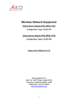
ACCESS POINT
User Manual
For the following models:
ULTIAIR 419KC
ULTIAIR 323KC
ULTIAIR 423KC
ULTIAIR 423KN
ULTIAIR 319KC
ULTIAIR 417SB
Contents
1. INTRODUCTION................................................................................................................5
1.2 License levels.............................................................................................................5
1.3 The information coded in model numbers of ULTIAIR devices - example: ...............6
1.4 Main features..............................................................................................................6
1.5 Typical applications.....................................................................................................6
2. INSTALLATION..................................................................................................................8
2.1 Checking the contents................................................................................................8
2.2 Description of interfaces.............................................................................................8
2.3 Connections................................................................................................................8
3. FIRST RUN........................................................................................................................9
3.1 Configuration with WinBox (in Windows OS).............................................................9
4. EXAMPLE CONFIGURATIONS......................................................................................12
4.1 Bridge - WDS............................................................................................................12
4.2 HotSpot.....................................................................................................................22
2
Warning
It is necessary to ensure safe operating conditions (among other things described in
this manual – to protect the device against direct strike of lightning, to use shielded cables
connecting the device to the PC or other peripherals). It is not allowed to make any changes to
the device – it will void warranty as well as legality of use.
Safety
The device has been designed and manufactured with utmost care for the safety of
installing and using. To ensure safe operation, the user should follow all warnings and
instructions in this manual and directions for use of the cooperating equipment (e.g. a PC).
Contents of the box
●
●
Antenna with assembled and sealed RouterBoard device, wireless adapter (card).
Power supply with PoE adapter.
During the delivery, make sure that the packaging is not damaged. In the case of any
damage you should not pick up the parcel or contact the vendor. Please, also check the
contents of the package shown in the list above.
Contents of the manual
This manual provides a detailed description of wireless ULTIAIR set, including its
installation, configuration, and operation. The user is obliged to read it carefully before
installation of the equipment and follow all instructions, especially those concerned with
safety.
Safe use rules
Each wireless transmission device ULTIAIR complies to international electric code.
Below there are the basic rules of safe operation of the devices:
●
●
●
●
●
●
●
●
●
●
power socket must be grounded in accordance with applicable regulations,
the set has to be installed and reviewed prior to switching on power supply,
before any maintenance the power has to be switched off,
the device is disabled only when all power cables and connections with other
equipment are completely disconnected,
it is not allowed to use power cables with broken insulation,
all installation work should be done by qualified personnel only,
the devices are not suitable for use in flammable environments,
the devices have to be protected against access of unauthorized people, especially
children,
the parts of the set have to be solidly mounted,
if the device is moved from a cool place to a warm environment, the moisture can
prevent proper operation – one should wait until the moisture has evaporated.
3
Notice: It is not allowed to touch the contacts of the sockets – risk of damage due to
electrostatic discharge!
Power
ULTIAIR wireless network device does not require an external power supply directly
connected to the device. The set includes PoE adapter. The power cord (plugged into AC
power outlet) is connected to its socket marked AC. The port marked LAN (Data Input
Port) is connected with computer or appropriate telecommunications equipment. The
outdoor/external part of the set is connected via Category 5 cable terminated with RJ-45
connector to the port marked PoE.
Operation environment
The antenna part of the set has been designed for outdoor use. It can operate in
adverse weather conditions (rain, snow, low and high temperature). However, it cannot be
placed close to chimneys, outdoor parts of air-conditioners, other antennas etc.
4
1. INTRODUCTION
1.1 Basic information
MikroTik RouterOS is a special operating system based on Linux, designed for
building advanced access points and routers with bandwidth management. Despite
advanced functions the system is easy to manage via WWW, system console, or a special,
user-friendly tool - Winbox.
1.2 License levels
License level
3 (WISPCPE)
4 (WISP)
Upgradable to
ROS v3.x
ROS v3.x
Initial Config Support
-
15 days
Wireless AP
-
yes
Wireless Client and Bridge
yes
yes
RIP, OSPF, BGP protocols
yes (v3 x86 =
RIP)
yes (v3 x86 = RIP,
OSPF)
EoIP tunnels
no limit (V3 = 1)
no limit
PPPoE tunnels
200 (V3 = 1)
200
PPTP tunnels
200 (V3 = 1)
200
L2TP tunnels
200 (V3 = 1)
200
VLAN interfaces
no limit (V3 = 1)
no limit
P2P firewall rules
no limit (V3 = 1)
no limit
NAT rules
no limit
no limit
HotSpot active users
1
200
RADIUS client
yes
yes
Queues
no limit
no limit
Web proxy
yes
yes
Synchronous interfaces
-
yes
User manager active
sessions
10 (v3 10)
10 (v3 20)
5
1.3 The information coded in model numbers of ULTIAIR devices - example:
ULTIAIR
4 19 K C
Intended use (K- client, B- base, N- bridge)
Antenna directivity (K- directional, S- sector, D- omnidirectional)
Antenna gain [dB]
Mikrotik license level
Family
1.4 Main features
●
●
●
●
●
●
Flexible configuration;
Possibility of creating advanced network systems;
Efficient data transmission (40 Mbit/s in Nstreme) .
Weather-resistant housing (IP 66);
Quick configuration of Access Point, Bridge, and HOTSPOT modes;
Easy installation.
1.5 Typical applications
●
Bridge
6
●
HotSpot
●
AP
●
Client (WISP)
7
2. INSTALLATION
2.1 Checking the contents
Before installation check the contents of the package (the list on page 3). above. In
any doubt contact the vendor.
2.2 Description of interfaces
1. Input - Ethernet interface (RJ-45)
1. Output (PoE) to ULITAIR - RJ-45
2. Ethernet input - RJ-45
3. Power cord (230V AC)
2.3 Connections
8
3. FIRST RUN
3.1 Configuration with WinBox (in Windows OS)
The Winbox utility can be downloaded from www.dipolnet.com (Download section).
The device has to be connected with a PC via Ethernet cable.
1. Run the utility.
2. Click on the three dots.
9
3. From the list displayed choose the device being configured.
4. In Login field enter „admin” (the Password field leave blank) and click Connect.
10
5. The WinBox menu will appear:
11
4. EXAMPLE CONFIGURATIONS
4.1 Bridge - WDS
Configuration OF BASE STATION (AP)
1. With WinBox the user can create a bridge, by clicking Bridge tab and +.
2. In the new window the user should enter bridge-wds (in Name field) and clik OK.
12
3. In New Bridge Port window click + and add “ethr1” interface to the created bridge.
Then click OK.
13
4. Configuration of wireless interface – enter Wireless menu and turn on radio
transmission (right click on “wlan1” and click Enable).
5. Configuration of wireless adapter (card) – double click on “wlan1” and choose Wireless
tab.
Set the Mode of work: AP Bridge, SSID: MikroTik, Frequency: (e.g.) 5180 MHz.
14
6. Then go to WDS tab and set dynamic WDS Mode and bridge-wds WDS default
Bridge, click OK.
15
7. IP address assignment. Enter IP tab and choose Addresses.
16
8. Click on +. In the window you should assign appropriate IP addresses.
9. In Address field enter 192.168.1.100/24 and choose Interface: ether1, confirm OK.
17
10. Click again on + and add another Address: 10.5.3.1/24 and choose Interface: bridgewds, confirm OK.
Configuration of client station (Station)
1. With WinBox utility create a bridge – click on Bridge and then +.
18
19
2. In New Interface window, enter wds-bridge (Name) and click OK.
20
3. In New Bridge Port window add “ether1” to the bridge, confirm OK.
21
4. Click + again and then add wlan1 (Interface) to the bridge, confirm OK.
5. Configuration of wireless interface. Enter Wireless menu. First, switch on the radio right click on wlan1 interface and then click on Enable.
22
6. Configuration of wireless adapter (card). Double click on wlan1 interface and go to
Wireless tab.
Set station wds (Mode), MikroTik (SSID), 5GHz (Band).
23
24
7. IP address assignment. Enter IP tab and choose Addresses.
8. Click on +. In the window you should assign appropriate IP addresses.
25
9. In Address field enter 192.168.1.101/24 and choose Interface: ether1, confirm OK.
26
10. Click again on + and add another Address: 10.5.3.1/24 and choose Interface: bridgewds, confirm OK.
11. You may test the bridge-wds pinging the 192.168.1.101 address from the local network
connected to the base station.
4.2 HotSpot
27
Configuration with WinBox.
1. IP address assignment. Enter IP tab and choose Addresses.
2. In the Address List window click on +. In the next window you should assign
appropriate IP addresses.
3. In Address field enter 192.168.1.2/24 and choose Interface: ether1, confirm OK.
28
4. Setting DNS servers – choose IP/DNS.
29
5. In DNS window click Settings.
6. Enter DNS addresses. As the Primary DNS: 194.204.159.1, and as the
Secondary DNS: 217.98.63.164. Then tick Allow Remote Requests and confirm OK.
7. Enter gateway address. Fist click on New Terminal.
30
In the new window input:
/ip route add gateway=192.168.1.1 (see the bottom line), confirm with ENTER and close
the window.
31
32
8. Configuring HotSpot - choose IP/Hotspot.
33
In the new window click on Hotspot Setup.
34
The wizard will help to configure the Hotspot. First, choose the HotSpot's interface. Select
wlan1 and click Next.
9. Local address of the interface – no change is needed. Click Next.
10. DHCP server pool - no change is needed. Click Next.
11. The next window allows to choose certificate (can be set none). Click Next.
12. SMTP server address (can be set to 0.0.0.0). Click Next.
35
13. You'll see the previously entered DNS servers. Click Next.
14. DNS server name (can be left blank). Click Next.
15. In the last window enter login and password, then click Next.
16. Successful setup is confirmed with this message:
36
17. Creating user profiles – go to User Profiles tab and click +.
18. In New Hotspot User Profile configure the user profile, then click OK.
37
19. Go to Users tab to add next users. To add next user click + , enter the name,
password, and the previously created profile.
20. After adding all users go to Wireless menu and configure wireless interface.
Switch on wireless networks – right click on wlan1 interface and then click Enable.
38
21. Configuring wireless adapter (card) – double click on wlan1 interface and go to
Wireless tab.
Set ap bridge (Mode), MikroTik (SSID), 2.4GHz-B/G (Band).
39
Copyright reserved:
DIPOL Szydlowski i
Wspolnicy Spolka Jawna
31-587 Krakow, ul. Cieplownicza 40
e-mail: [email protected]
Internet: www.dipolnet.com
NIP: PL 678-01-01-049
REGON: 350509592
KRS: 0000094703